EP0950842B1 - Metallische Zylinderkopfdichtung - Google Patents
Metallische Zylinderkopfdichtung Download PDFInfo
- Publication number
- EP0950842B1 EP0950842B1 EP99114922A EP99114922A EP0950842B1 EP 0950842 B1 EP0950842 B1 EP 0950842B1 EP 99114922 A EP99114922 A EP 99114922A EP 99114922 A EP99114922 A EP 99114922A EP 0950842 B1 EP0950842 B1 EP 0950842B1
- Authority
- EP
- European Patent Office
- Prior art keywords
- cylinder head
- head gasket
- deformation limiter
- passage
- bead
- Prior art date
- Legal status (The legal status is an assumption and is not a legal conclusion. Google has not performed a legal analysis and makes no representation as to the accuracy of the status listed.)
- Expired - Lifetime
Links
- 239000011324 bead Substances 0.000 claims description 30
- 238000002485 combustion reaction Methods 0.000 claims description 14
- 230000002093 peripheral effect Effects 0.000 claims 3
- 238000009827 uniform distribution Methods 0.000 claims 2
- 238000007789 sealing Methods 0.000 description 5
- 239000002184 metal Substances 0.000 description 2
- 229910000639 Spring steel Inorganic materials 0.000 description 1
- 238000004026 adhesive bonding Methods 0.000 description 1
- 239000000498 cooling water Substances 0.000 description 1
- 238000004049 embossing Methods 0.000 description 1
- 210000003746 feather Anatomy 0.000 description 1
- 239000000446 fuel Substances 0.000 description 1
- 238000009434 installation Methods 0.000 description 1
- 230000003993 interaction Effects 0.000 description 1
- 239000000725 suspension Substances 0.000 description 1
- 238000003466 welding Methods 0.000 description 1
Images
Classifications
-
- F—MECHANICAL ENGINEERING; LIGHTING; HEATING; WEAPONS; BLASTING
- F16—ENGINEERING ELEMENTS AND UNITS; GENERAL MEASURES FOR PRODUCING AND MAINTAINING EFFECTIVE FUNCTIONING OF MACHINES OR INSTALLATIONS; THERMAL INSULATION IN GENERAL
- F16J—PISTONS; CYLINDERS; SEALINGS
- F16J15/00—Sealings
- F16J15/02—Sealings between relatively-stationary surfaces
- F16J15/06—Sealings between relatively-stationary surfaces with solid packing compressed between sealing surfaces
- F16J15/08—Sealings between relatively-stationary surfaces with solid packing compressed between sealing surfaces with exclusively metal packing
- F16J15/0818—Flat gaskets
- F16J15/0825—Flat gaskets laminated
-
- F—MECHANICAL ENGINEERING; LIGHTING; HEATING; WEAPONS; BLASTING
- F02—COMBUSTION ENGINES; HOT-GAS OR COMBUSTION-PRODUCT ENGINE PLANTS
- F02F—CYLINDERS, PISTONS OR CASINGS, FOR COMBUSTION ENGINES; ARRANGEMENTS OF SEALINGS IN COMBUSTION ENGINES
- F02F11/00—Arrangements of sealings in combustion engines
- F02F11/002—Arrangements of sealings in combustion engines involving cylinder heads
-
- F—MECHANICAL ENGINEERING; LIGHTING; HEATING; WEAPONS; BLASTING
- F02—COMBUSTION ENGINES; HOT-GAS OR COMBUSTION-PRODUCT ENGINE PLANTS
- F02F—CYLINDERS, PISTONS OR CASINGS, FOR COMBUSTION ENGINES; ARRANGEMENTS OF SEALINGS IN COMBUSTION ENGINES
- F02F1/00—Cylinders; Cylinder heads
- F02F1/02—Cylinders; Cylinder heads having cooling means
- F02F1/10—Cylinders; Cylinder heads having cooling means for liquid cooling
- F02F2001/104—Cylinders; Cylinder heads having cooling means for liquid cooling using an open deck, i.e. the water jacket is open at the block top face
-
- F—MECHANICAL ENGINEERING; LIGHTING; HEATING; WEAPONS; BLASTING
- F16—ENGINEERING ELEMENTS AND UNITS; GENERAL MEASURES FOR PRODUCING AND MAINTAINING EFFECTIVE FUNCTIONING OF MACHINES OR INSTALLATIONS; THERMAL INSULATION IN GENERAL
- F16J—PISTONS; CYLINDERS; SEALINGS
- F16J15/00—Sealings
- F16J15/02—Sealings between relatively-stationary surfaces
- F16J15/06—Sealings between relatively-stationary surfaces with solid packing compressed between sealing surfaces
- F16J15/08—Sealings between relatively-stationary surfaces with solid packing compressed between sealing surfaces with exclusively metal packing
- F16J15/0818—Flat gaskets
- F16J2015/0843—Flat gaskets with an edge portion folded over the plate itself
-
- F—MECHANICAL ENGINEERING; LIGHTING; HEATING; WEAPONS; BLASTING
- F16—ENGINEERING ELEMENTS AND UNITS; GENERAL MEASURES FOR PRODUCING AND MAINTAINING EFFECTIVE FUNCTIONING OF MACHINES OR INSTALLATIONS; THERMAL INSULATION IN GENERAL
- F16J—PISTONS; CYLINDERS; SEALINGS
- F16J15/00—Sealings
- F16J15/02—Sealings between relatively-stationary surfaces
- F16J15/06—Sealings between relatively-stationary surfaces with solid packing compressed between sealing surfaces
- F16J15/08—Sealings between relatively-stationary surfaces with solid packing compressed between sealing surfaces with exclusively metal packing
- F16J15/0818—Flat gaskets
- F16J2015/085—Flat gaskets without fold over
Definitions
- the invention relates to a metallic cylinder head gasket according to the preamble of claim 1.
- the seal is achieved by raising the cylinder head gasket along the combustion chamber and through a bead behind it performed.
- the latter acts as a spring element and follows due to the ignition pressure occurring vertical relative movements of the cylinder head relative to the Cylinder block.
- the relief must not be complete, but only to the extent that a minimum deformation occurs at the highest occurring Combustion chamber pressure ensures the required sealing. Between these two The corner of the deformation is the working area of the bead.
- a cylinder head gasket in which a Carrier plate is provided, on both sides of which a corrugated cover plate is arranged, wherein the bead extends around the edge of the combustion chamber.
- the Carrier sheet is here on both sides with one around the edge of the combustion chamber trending, triangular cut notch that the corresponding bead of the respective cover plate partially.
- the beading is on the side in their Supported inclined areas, while the bottom of the notch remains free. To this In this way, the bead contact area is eliminated.
- Profiling the notch in The circumferential direction does not exist, it has a constant cross-section.
- the object of the invention is to provide a metallic cylinder head gasket to create the type mentioned above, in which the bead work area over the Combustion chamber size is evened out.
- the inner deformation limiter has a stop for the or has the cover plates in the clamped state of the seal and the Cover plates a radial distance or protrusion from the stop have, from a certain height deformation of the bead and thus one certain change in length of the cover plates to the stop.
- a further deflection of the bead is no longer possible with one Change in length of the cover plates, so that there is a kind of frog feather effect results and for further deformation of the bead until it rests on the Deformation limiter requires a considerably higher effort.
- a higher spring force of the bead is achieved, the Ultimately maximum value from the support on the deformation limiter and its Height profiling depends.
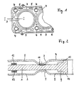
- the cylinder head gasket shown in FIGS. 1 and 2 comprises a carrier plate 1, on the two sides of which a cover plate 2 is arranged.
- the Seal i.e. Carrier plate 1 and cover plates 2 has a number of openings 3 corresponding to the combustion chambers of the associated fuel press and Screw through holes 4 for screws that are used to clamp Cylinder head and block are used, as well as through openings 5, 6 for cooling water or oil.
- the usually made of spring steel and otherwise plan Cover plates 2 are provided with beads 7, which are left at a distance straight sheet metal section 8 arranged in the edge region of the opening 3 and Carrier plate 1 are directed.
- the otherwise flat carrier plate 1 is in the edge region of the openings 3 each with an inner deformation limiter 9 for the adjacent bead 7 Mistake.
- 2 is the deformation limiter in this embodiment 9 thereby formed a section with a rectangular section, the Deformation limiter 9 is arranged practically centrally between the cover plates 2 and thus has the same effect with respect to the beads 7 of both cover plates 2.
- the strength of the deformation limiter 9 is such that the straight sheet metal sections 8 of the cover sheets 2 when clamping the seal this come to riot while at the same time the beads 7 are pressed be claimed.
- the deformation limiter 9 sets the corner points of the Bead work area according to the specified operating points, a variation to adapt this to predetermined design points the height and / or width profiling of the deformation limiter 9 along the circumference of the opening 3 can be provided.
- the height profiling can by appropriate processing of the deformation limiter 9.
- the Width profiling can be done in this embodiment by attaching a appropriate cutout for the opening 3.
- the deformation limiter 9 is additionally formed with a step provided a stop 10, the height and / or in a variable manner can be profiled in width.
- the cover plates 2 have a radial distance or Protruding from the stop 10, so that from a certain Height deformation of the bead 7 and thus a certain change in length of the Cover plates 2 push them against the stop 10. This goes one more Deflection of the bead 7 no longer with a change in length of the cover plates 2 hand in hand, so that for further deformation of the bead 7 until they rest on the Deformation limiter 9 a considerably higher effort is required. On in this way a higher spring force of the bead is achieved, the Ultimately, maximum value from the support on the deformation limiter 9 and whose height profile depends.
- a further, external deformation limiter can additionally be used for the bead 7 12 may be provided, which is concentric with the preforming limiter 9, but on the side of the bead 7 facing away from it, i.e. on the combustion chamber side of the bead 7 is arranged.
- both deformation limiters 9, 12 can be achieved in that the deflection of the bead 7 takes place practically perpendicular to the sealing plane.
- the deformation limiter 12 which either on the associated Cover plate 2 or in particular on the carrier plate, for example by gluing or Welding is attached, can also be variable in height and / or be profiled in width. Since the deformation limiter 12 is further out, the Force relationships not with those in the area of the inner deformation limiter 9 identical, accordingly, the variation in height and / or Width profiling can be different.
- the carrier plate 1 can be in the contact area of the Beading 7 in addition to adapting the corner points of the beading work area constructively predetermined design points can be varied in level. This can by a different over the combustion chamber perimeter 11th (Embossing) and / or an increase (application) of the relevant carrier sheet section happen.
- the deformation limiter 9 can also be separated from the carrier plate 1 trained and optionally welded to it.
Landscapes
- Engineering & Computer Science (AREA)
- General Engineering & Computer Science (AREA)
- Mechanical Engineering (AREA)
- Chemical & Material Sciences (AREA)
- Combustion & Propulsion (AREA)
- Gasket Seals (AREA)
Description
Claims (8)
- Metallische Zylinderkopfdichtung für eine Brennkraftmaschine, mit wenigstens einem Deckblech (2) und einem Trägerblech (1), die übereinander angeordnet sind und die mit Schraubendurchtrittslöchern (4) und mit einer Öffnung (3) oder mit mehreren nebeneinander angeordneten Öffnungen (3) entsprechend den Brennkammern der Brennkraftmaschine versehen sind, wobei in dem wenigstens einen Deckblech (2) um jede Öffnung (3) herum mit Abstand zu dieser unter Belassung eines geraden Blechabschnitts (8) im Öffnungsrandbereich eine zum Trägerblech (1) weisende Sicke (7) vorgesehen ist, für deren Schutz benachbart zu dieser um jede Öffnung (3) herum verlaufend ein innerer Verformungsbegrenzer (9) vorgesehen ist, auf dem das wenigstens eine Deckblech (2) im eingespannten Zustand der Dichtung aufliegt, dadurch gekennzeichnet, daß eine sich in Umfangsrichtung des Sickenaufstandsbereichs erstreckende, Vertiefungen (11) und/oder Erhöhungen aufweisende Profiländerung des Trägerblechs (1) vorgesehen ist.
- Zylinderkopfdichtung nach Anspruch 1, dadurch gekennzeichnet, daß die Vertiefungen (11) geprägt sind.
- Zylinderkopfdichtung nach Anspruch 1 oder 2, dadurch gekennzeichnet, daß der innere Verformungsbegrenzer (9) zusätzlich zur Auflagefläche für das wenigstens eine Deckblech (2) einen Anschlag (11) für das wenigstens eine Deckblech (2) im eingespannten Zustand der Dichtung aufweist.
- Zylinderkopfdichtung nach Anspruch 3, dadurch gekennzeichnet, daß der innere Verformungsbegrenzer (9) im Schnitt etwa rechteckig ist.
- Zylinderkopfdichtung nach einem der Ansprüche 1 bis 4, dadurch gekennzeichnet, daß auf jeder Seite des Trägerblechs (1), auf der sich ein Deckblech (2) befindet, auf der der jeweiligen Öffnung (3) abgewandten Seite der Sicke (7) ein äußerer Verformungsbegrenzer (12) konzentrisch zum inneren Verformungsbegrenzer (9) für die benachbarte Sicke (7) vorgesehen ist.
- Zylinderkopfdichtung nach Anspruch 5, dadurch gekennzeichnet, daß der äußere Verformungsbegrenzer (12) entsprechend einer gleichmäßigen Kraftverteilung im Öffnungsrandbereich in Umfangsrichtung höhen- und/oder breitenveränderlich ist.
- Zylinderkopfdichtung nach einem der Ansprüche 1 bis 6, dadurch gekennzeichnet, daß der innere Verformungsbegrenzer (9) entsprechend einer gleichmäßigen Kraftverteilung im Öffnungsrandbereich in Umfangsrichtung höhenund/oder breitenveränderlich ist.
- Zylinderkopfdichtung nach einem der Ansprüche 1 bis 7, dadurch gekennzeichnet, daß das Trägerblech (1) zwischen zwei gesickten Deckblechen (2) angeordnet ist und der innere Verformungsbegrenzer (9) etwa mittig zwischen beiden Deckblechen (2) angeordnet ist.
Applications Claiming Priority (7)
| Application Number | Priority Date | Filing Date | Title |
|---|---|---|---|
| DE19513360 | 1995-04-08 | ||
| DE1995113361 DE19513361C1 (de) | 1995-04-08 | 1995-04-08 | Metallische Zylinderkopfdichtung |
| DE1995113362 DE19513362C1 (de) | 1995-04-08 | 1995-04-08 | Metallische Zylinderkopfdichtung |
| DE1995113360 DE19513360C1 (de) | 1995-04-08 | 1995-04-08 | Metallische Zylinderkopfdichtung |
| DE19513361 | 1995-04-08 | ||
| DE19513362 | 1995-05-08 | ||
| EP96104758A EP0736709B1 (de) | 1995-04-08 | 1996-03-26 | Metallische Zylinderkopfdichtung |
Related Parent Applications (1)
| Application Number | Title | Priority Date | Filing Date |
|---|---|---|---|
| EP96104758A Division EP0736709B1 (de) | 1995-04-08 | 1996-03-26 | Metallische Zylinderkopfdichtung |
Publications (3)
| Publication Number | Publication Date |
|---|---|
| EP0950842A2 EP0950842A2 (de) | 1999-10-20 |
| EP0950842A3 EP0950842A3 (de) | 2000-01-12 |
| EP0950842B1 true EP0950842B1 (de) | 2003-07-16 |
Family
ID=27215030
Family Applications (2)
| Application Number | Title | Priority Date | Filing Date |
|---|---|---|---|
| EP99114922A Expired - Lifetime EP0950842B1 (de) | 1995-04-08 | 1996-03-26 | Metallische Zylinderkopfdichtung |
| EP96104758A Expired - Lifetime EP0736709B1 (de) | 1995-04-08 | 1996-03-26 | Metallische Zylinderkopfdichtung |
Family Applications After (1)
| Application Number | Title | Priority Date | Filing Date |
|---|---|---|---|
| EP96104758A Expired - Lifetime EP0736709B1 (de) | 1995-04-08 | 1996-03-26 | Metallische Zylinderkopfdichtung |
Country Status (2)
| Country | Link |
|---|---|
| EP (2) | EP0950842B1 (de) |
| DE (2) | DE59610609D1 (de) |
Cited By (1)
| Publication number | Priority date | Publication date | Assignee | Title |
|---|---|---|---|---|
| US7997585B2 (en) | 2001-04-05 | 2011-08-16 | Elringklinger Ag | Cylinder head gasket |
Families Citing this family (4)
| Publication number | Priority date | Publication date | Assignee | Title |
|---|---|---|---|---|
| DE19835848A1 (de) * | 1998-08-07 | 2000-03-02 | Reinz Dichtungs Gmbh | Flachdichtung und Verfahren zum Herstellen einer Flachdichtung |
| DE10224856B4 (de) * | 2002-06-05 | 2004-05-27 | Elringklinger Ag | Zylinderkopfdichtung |
| DE10310014B4 (de) * | 2003-02-28 | 2009-09-10 | Reinz-Dichtungs-Gmbh | Zylinderkopf-Flachdichtung |
| US8128099B2 (en) | 2005-11-14 | 2012-03-06 | Dana Automotive Systems Group, Llc | Gasket |
Citations (2)
| Publication number | Priority date | Publication date | Assignee | Title |
|---|---|---|---|---|
| EP0230804A2 (de) * | 1985-12-27 | 1987-08-05 | Nihon Metal Gasket Kabushiki Kaisha | Metalldichtung |
| EP0306766A2 (de) * | 1987-09-05 | 1989-03-15 | Nihon Metal Gasket Kabushiki Kaisha | Laminierte Metalldichtung |
Family Cites Families (4)
| Publication number | Priority date | Publication date | Assignee | Title |
|---|---|---|---|---|
| GB2097871B (en) * | 1981-05-01 | 1985-03-20 | Nicholson Terence Peter | Improvements relating to gaskets |
| DE69209009T2 (de) * | 1991-11-25 | 1996-08-29 | Taiho Kogyo Co Ltd | Metalldichtung |
| US5211408A (en) * | 1992-02-19 | 1993-05-18 | Ishikawa Gasket Co., Ltd. | Metal laminate gasket with a sealing groove |
| JP3581162B2 (ja) * | 1993-07-07 | 2004-10-27 | 日本リークレス工業株式会社 | 金属ガスケットの製造方法 |
-
1996
- 1996-03-26 DE DE59610609T patent/DE59610609D1/de not_active Expired - Lifetime
- 1996-03-26 EP EP99114922A patent/EP0950842B1/de not_active Expired - Lifetime
- 1996-03-26 EP EP96104758A patent/EP0736709B1/de not_active Expired - Lifetime
- 1996-03-26 DE DE59604933T patent/DE59604933D1/de not_active Expired - Fee Related
Patent Citations (2)
| Publication number | Priority date | Publication date | Assignee | Title |
|---|---|---|---|---|
| EP0230804A2 (de) * | 1985-12-27 | 1987-08-05 | Nihon Metal Gasket Kabushiki Kaisha | Metalldichtung |
| EP0306766A2 (de) * | 1987-09-05 | 1989-03-15 | Nihon Metal Gasket Kabushiki Kaisha | Laminierte Metalldichtung |
Cited By (1)
| Publication number | Priority date | Publication date | Assignee | Title |
|---|---|---|---|---|
| US7997585B2 (en) | 2001-04-05 | 2011-08-16 | Elringklinger Ag | Cylinder head gasket |
Also Published As
| Publication number | Publication date |
|---|---|
| EP0950842A3 (de) | 2000-01-12 |
| EP0736709A1 (de) | 1996-10-09 |
| EP0950842A2 (de) | 1999-10-20 |
| DE59604933D1 (de) | 2000-05-18 |
| DE59610609D1 (de) | 2003-08-21 |
| EP0736709B1 (de) | 2000-04-12 |
Similar Documents
| Publication | Publication Date | Title |
|---|---|---|
| EP0747614B1 (de) | Metallische Zylinderkopfdichtung | |
| DE3820796C2 (de) | ||
| DE3915434C2 (de) | ||
| EP0877183B1 (de) | Metallische Zylinderkopfdichtung | |
| EP0740092B1 (de) | Metallische Zylinderkopfdichtung | |
| DE60108672T2 (de) | Zylinderkopfdichtung | |
| DE3001730A1 (de) | Zylinderkopfdichtung | |
| EP1635093B1 (de) | Zylinderkopfdichtung | |
| EP3115656B1 (de) | Flachdichtung | |
| DE19601324C2 (de) | Zylinderkopfdichtung | |
| DE69118364T2 (de) | Stahllaminatdichtung mit erweiterten Dichtungsflächen | |
| EP1291561B1 (de) | Zylinderkopfdichtung | |
| DE19751293A1 (de) | Einschichtige oder mehrschichtige Metallzylinderkopfdichtung und Verfahren zu ihrer Herstellung | |
| EP1158223B1 (de) | Zylinderkopfdichtung | |
| DE19513360C1 (de) | Metallische Zylinderkopfdichtung | |
| EP0950842B1 (de) | Metallische Zylinderkopfdichtung | |
| DE19513361C1 (de) | Metallische Zylinderkopfdichtung | |
| DE8102660U1 (de) | Flachdichtung, insbesondere Zylinderkopfdichtung für Verbrennungskraftmaschinen | |
| EP2989356B1 (de) | Metallische flachdichtung sowie verfahren zu deren herstellung | |
| DE69115651T3 (de) | Geschichtete Stahlblechabdichtung mit Schutzteil | |
| DE19513362C1 (de) | Metallische Zylinderkopfdichtung | |
| DE19549595C2 (de) | Zylinderkopfdichtung | |
| DE19822143C1 (de) | Zylinderkopfdichtung | |
| DE19934825C1 (de) | Zylinderkopfdichtung | |
| DE3915566C2 (de) |
Legal Events
| Date | Code | Title | Description |
|---|---|---|---|
| PUAI | Public reference made under article 153(3) epc to a published international application that has entered the european phase |
Free format text: ORIGINAL CODE: 0009012 |
|
| AC | Divisional application: reference to earlier application |
Ref document number: 736709 Country of ref document: EP |
|
| AK | Designated contracting states |
Kind code of ref document: A2 Designated state(s): DE FR GB IT |
|
| PUAL | Search report despatched |
Free format text: ORIGINAL CODE: 0009013 |
|
| AK | Designated contracting states |
Kind code of ref document: A3 Designated state(s): DE FR GB IT |
|
| 17P | Request for examination filed |
Effective date: 20000203 |
|
| AKX | Designation fees paid |
Free format text: DE FR GB IT |
|
| RAP1 | Party data changed (applicant data changed or rights of an application transferred) |
Owner name: ELRINGKLINGER AG |
|
| 17Q | First examination report despatched |
Effective date: 20010629 |
|
| GRAH | Despatch of communication of intention to grant a patent |
Free format text: ORIGINAL CODE: EPIDOS IGRA |
|
| GRAH | Despatch of communication of intention to grant a patent |
Free format text: ORIGINAL CODE: EPIDOS IGRA |
|
| GRAA | (expected) grant |
Free format text: ORIGINAL CODE: 0009210 |
|
| AC | Divisional application: reference to earlier application |
Ref document number: 0736709 Country of ref document: EP Kind code of ref document: P |
|
| AK | Designated contracting states |
Designated state(s): DE FR GB IT |
|
| REG | Reference to a national code |
Ref country code: GB Ref legal event code: FG4D Free format text: NOT ENGLISH |
|
| REF | Corresponds to: |
Ref document number: 59610609 Country of ref document: DE Date of ref document: 20030821 Kind code of ref document: P |
|
| GBT | Gb: translation of ep patent filed (gb section 77(6)(a)/1977) | ||
| ET | Fr: translation filed | ||
| PLBE | No opposition filed within time limit |
Free format text: ORIGINAL CODE: 0009261 |
|
| STAA | Information on the status of an ep patent application or granted ep patent |
Free format text: STATUS: NO OPPOSITION FILED WITHIN TIME LIMIT |
|
| 26N | No opposition filed |
Effective date: 20040419 |
|
| PGFP | Annual fee paid to national office [announced via postgrant information from national office to epo] |
Ref country code: GB Payment date: 20090325 Year of fee payment: 14 |
|
| PGFP | Annual fee paid to national office [announced via postgrant information from national office to epo] |
Ref country code: IT Payment date: 20090325 Year of fee payment: 14 |
|
| GBPC | Gb: european patent ceased through non-payment of renewal fee |
Effective date: 20100326 |
|
| PG25 | Lapsed in a contracting state [announced via postgrant information from national office to epo] |
Ref country code: GB Free format text: LAPSE BECAUSE OF NON-PAYMENT OF DUE FEES Effective date: 20100326 Ref country code: IT Free format text: LAPSE BECAUSE OF NON-PAYMENT OF DUE FEES Effective date: 20100326 |
|
| PGFP | Annual fee paid to national office [announced via postgrant information from national office to epo] |
Ref country code: FR Payment date: 20110404 Year of fee payment: 16 |
|
| PGFP | Annual fee paid to national office [announced via postgrant information from national office to epo] |
Ref country code: DE Payment date: 20110524 Year of fee payment: 16 |
|
| REG | Reference to a national code |
Ref country code: FR Ref legal event code: ST Effective date: 20121130 |
|
| PG25 | Lapsed in a contracting state [announced via postgrant information from national office to epo] |
Ref country code: FR Free format text: LAPSE BECAUSE OF NON-PAYMENT OF DUE FEES Effective date: 20120402 |
|
| REG | Reference to a national code |
Ref country code: DE Ref legal event code: R119 Ref document number: 59610609 Country of ref document: DE Effective date: 20121002 |
|
| PG25 | Lapsed in a contracting state [announced via postgrant information from national office to epo] |
Ref country code: DE Free format text: LAPSE BECAUSE OF NON-PAYMENT OF DUE FEES Effective date: 20121002 |