EP0950880A2 - Monochromateur et dispositif d'analyse optique l'utilisant - Google Patents
Monochromateur et dispositif d'analyse optique l'utilisant Download PDFInfo
- Publication number
- EP0950880A2 EP0950880A2 EP99107054A EP99107054A EP0950880A2 EP 0950880 A2 EP0950880 A2 EP 0950880A2 EP 99107054 A EP99107054 A EP 99107054A EP 99107054 A EP99107054 A EP 99107054A EP 0950880 A2 EP0950880 A2 EP 0950880A2
- Authority
- EP
- European Patent Office
- Prior art keywords
- monochromator
- arm
- linear motor
- light
- fixed
- Prior art date
- Legal status (The legal status is an assumption and is not a legal conclusion. Google has not performed a legal analysis and makes no representation as to the accuracy of the status listed.)
- Withdrawn
Links
Images

Classifications
-
- G—PHYSICS
- G01—MEASURING; TESTING
- G01J—MEASUREMENT OF INTENSITY, VELOCITY, SPECTRAL CONTENT, POLARISATION, PHASE OR PULSE CHARACTERISTICS OF INFRARED, VISIBLE OR ULTRAVIOLET LIGHT; COLORIMETRY; RADIATION PYROMETRY
- G01J3/00—Spectrometry; Spectrophotometry; Monochromators; Measuring colours
- G01J3/02—Details
- G01J3/06—Scanning arrangements arrangements for order-selection
Definitions
- the present invention relates to a monochromator used in a spectrophotometer or other optical analyzing device.
- a spectrophotometer includes a monochromator for obtaining monochromatic light of a preset or desired wavelength.
- the monochromator generally includes a light-dispersing element, such as a diffraction grating, and a driving mechanism for rotating the light-dispersing element.
- the driving mechanism rotates the light-dispersing element, the orientation of the light-dispersing element with respect to the incident path changes, whereby wavelengths within a preset range are scanned.
- the wavelength range to be scanned is determined variously based on the purpose of the analysis, the type of spectrophotometer, and other factors.
- the wavelength scanning range is preset at 190-1100 nm for an analysis of visible and ultraviolet light, and 700-1500 nm or 1000-2500 nm for an analysis of near infrared light.
- the angular range of rotation of the light-dispersing element is preset at about 20-30 degrees, irrespective of the wavelength range.
- One type includes a sine bar for converting a linear movement to a rotary movement, and another type uses an open loop control of a step motor and reduction gears.
- a third type using a closed loop control of a DC servomotor is also known.
- the wavelength scanning speed is very high, and there is hardly any wavelength discrepancy because the mechanism includes a means for determining the rotational Position of the light-dispersing element.
- This type of mechanism has a drawback due to the use of the DC servomotor. That is, commercially available DC servomotors are designed for producing continuous rotation, and are not suitable for fractional rotation (for example, only 20 to 30 degrees out of 360 degrees), and are particularly unsuitable for producing reciprocal movement within a preset angular range. When this type of motor is used for rotating the light-dispersing element, it is difficult to stabilize the scanning speed within a preset angular range. Therefore, when output light from the light-dispersing element is sampled at a preset time point or points within a predetermined wavelength scanning range, the accuracy and reproducibility of the wavelength corresponding to each preset time point is poor.
- an object of the present invention is to provide a monochromator constructed so that wavelength scanning can be carried out at a high and constant speed.
- the present invention proposes a monochromator which includes:
- linear motor is a modified voice-coil linear motor constructed so that the moving part moves reciprocally within the preset angular range along an arc.
- position detector is a rotary encoder.
- the controller detects the rotational position of the rotor based on the output signal of the position detector during the wavelength scanning, and controls the driving voltage or driving current supplied to the linear motor so that the rotor moves at a fixed speed within the preset angular range.
- the controller may instruct the linear motor to move the rotor by a preset angle for each preset time period.
- linear motors are highly responsive to the driving voltage or driving current supplied thereto and the moving speed produced thereby is highly stable. Accordingly, when the controller controls the linear motor as described above, the rotor with the light-dispersing element fixed thereto rotates stably at a high speed within the preset angular range, maintaining a preset angular velocity. As the rotor rotates, the wavelength of monochromatic light obtained with the light-dispersing element varies continuously at a stable rate.
- a spectrophotometer includes a light source for generating polychromatic light, a sample holder for holding a sample to be analyzed, a photodetector for detecting light passing through or reflected by the sample, and a data processor that samples an output signal from the photodetector.
- the spectrophotometer further includes a monochromator, the sample holder is placed either between the light source and the monochromator or between the monochromator and the photodetector. In the former case, the polychromatic light passes through the sample or is reflected by the sample, and enters the monochromator.
- the monochromator according to the present invention is constructed so that the light-dispersing element is rotated at a fixed, high speed. As a result, the time required for wavelength scanning is considerably lessened.
- the spectrophotometer having the monochromator according to the present invention when, for example, output light from the light-dispersing element is sampled at a preset time point or points within a predetermined wavelength scanning range, the accuracy and reproducibility of the wavelength corresponding to each preset time point is high.
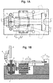
- the monochromator has a T-shaped horizontal arm 1.
- a vertical rotation shaft 3, which is supported by a pair of preload bearing units 4, is fixed at a near end of the stem part of the T-shaped arm 1.
- the outer rings of the bearing units 4 are fixed to a base 2, allowing the arm 1 to rotate on the axis of the rotation shaft 3 smoothly and firmly while keeping its horizontal position.
- the angular resolution of the rotary encoder 7 is required to be smaller than the minimal angular movement ( ⁇ ) of the diffraction grating 6 that determines the minimal wavelength resolution of the monochromator.
- ⁇ minimal angular movement
- the above requirement as to resolution is met by providing the slits at angular intervals smaller than the minimal angular movement ⁇ .
- the angular interval of the slits can be determined adequately small, because the outermost end of the crossbar 71 is farther from the rotation shaft than a position where a linear motor 9, which will be described later, exerts a driving force to the arm 1.
- an arm detector 8 for determining the origin of the rotary encoder 7 is provided near the rotary encoder 7.
- the arm detector 8 detects the arm 1 and generates a detection signal. Based on this detection signal and the above-described pulse trains, the absolute rotational position of the arm 1 is calculated.
- the linear motor 9 rotates the arm 1, and the rotary encoder 7 generates the two trains of pulse signals as described above.
- the microcomputer 10 modifies the control data.
- the linear motor 9 is controlled by such a closed loop control.
- the wavelength scanning by the spectrophotometer is operated as follows. First, when two wavelength values ⁇ 1 and ⁇ 2 are determined as the minimum and maximum wavelengths defining a wavelength range to be scanned, the microcomputer 10 controls the linear motor 9 to bring the arm 1 to a rotational position (original position) where the arm detector 8 detects the arm 1 and generates a detection signal. This operation of bringing the arm 1 to the original position may be preferably performed at the begining of every analysis.
- the monochromatic light detected by the photodetector 20 has a known wavelength ( ⁇ 0) determined by the type or structure (specified by the blaze angle, for example) of the diffraction grating 6, the position of the origin detector 8, etc.
- the microcomputer 10 determines the moving direction by comparing ⁇ 0 and ⁇ 1, and drives the linear motor 9 to move the arm 1 in that direction. Meanwhile, the microcomputer 10 counts pulse signals in the pulse train A or B generated by the rotary encoder 7 and determines whether the arm 1 is at a starting position corresponding to the wavelength ⁇ 1. When it is determined that the arm 1 is at the starting position, the microcomputer 10 stops driving the linear motor 9, ready to Start the wavelength scanning.
- the microcomputer 10 measures the pulse-repetition period of the pulse train (A or B) every time it receives a new pulse from the rotary encoder 7. Then, the microcomputer 10 calculates the difference between the calculated period and a preset reference period as a deviation index, and modifies the control data so that the deviation index is maintained at zero or a constant value. For example, when the speed of the arm 1 decreases, the actual pulse-repetition period of the pulse trains becomes longer and the deviation index becomes accordingly larger. In such a case, the microcomputer 10 modifies the control data so that the driving voltage supplied to the linear motor 9 increases, whereby the speed of the arm 1 increases. Thus, the microcomputer 10 regulates the driving voltage or driving current to control the linear motor 9 so that the arm 1 moves at a constant speed throughout the wavelength scanning.
- the microcomputer 10 determines the rotational position of the arm 1 at each time point based on the number of pulses transmitted from the rotary encoder 7, and calculates the wavelength corresponding to the rotational position based on the angular distance of the rotational position from the original position and the above-described original wavelength ⁇ 0.
- the microcomputer 10 sends a timing signal to the data processor 21, and restarts the counting of the pulses from zero.
- the data processor 21 samples the output signal of the photodetector 20 at the time point, produces measurement data representing the strength of the sampled output signal, and stores the data in its memory.
- the wavelengths are scanned from the minimum wavelength ⁇ 1 to the maximum wavelength ⁇ 2. It is of course possible that the wavelengths are scanned from the maximum wavelength ⁇ 2 to the minimum wavelength ⁇ 1. Also, the wavelengths may be scanned in both directions continuously. That is, for example, the wavelengths are first scanned from the minimum to the maximum wavelength, and when the arm 1 reaches the rotational position corresponding to the maximum wavelength, the microcomputer 10 reverses the polarity of the driving voltage supplied to the linear motor 9. After that, the wavelengths are scanned backwards.
- the deviation index may be calculated based on the phase difference between the two trains of pulse signals from the rotary encoder 7. For example, the difference between the value of the above-mentioned phase difference and a predetermined reference value is available as the deviation index.
Landscapes
- Physics & Mathematics (AREA)
- Spectroscopy & Molecular Physics (AREA)
- General Physics & Mathematics (AREA)
- Spectrometry And Color Measurement (AREA)
Applications Claiming Priority (2)
| Application Number | Priority Date | Filing Date | Title |
|---|---|---|---|
| JP12416798 | 1998-04-17 | ||
| JP12416798A JP3783400B2 (ja) | 1998-04-17 | 1998-04-17 | モノクロメータ |
Publications (2)
| Publication Number | Publication Date |
|---|---|
| EP0950880A2 true EP0950880A2 (fr) | 1999-10-20 |
| EP0950880A3 EP0950880A3 (fr) | 2000-08-09 |
Family
ID=14878616
Family Applications (1)
| Application Number | Title | Priority Date | Filing Date |
|---|---|---|---|
| EP99107054A Withdrawn EP0950880A3 (fr) | 1998-04-17 | 1999-04-09 | Monochromateur et dispositif d'analyse optique l'utilisant |
Country Status (4)
| Country | Link |
|---|---|
| US (1) | US6034767A (fr) |
| EP (1) | EP0950880A3 (fr) |
| JP (1) | JP3783400B2 (fr) |
| CA (1) | CA2269011A1 (fr) |
Families Citing this family (6)
| Publication number | Priority date | Publication date | Assignee | Title |
|---|---|---|---|---|
| JP2000310563A (ja) | 1999-04-27 | 2000-11-07 | Shimadzu Corp | モノクロメータ |
| US6587196B1 (en) * | 2000-01-26 | 2003-07-01 | Sensys Medical, Inc. | Oscillating mechanism driven monochromator |
| WO2002099368A1 (fr) * | 2001-06-01 | 2002-12-12 | Cidra Corporation | Contrôleur de porteuse optique |
| US7253897B2 (en) | 2001-06-01 | 2007-08-07 | Cidra Corporation | Optical spectrum analyzer |
| WO2005050163A2 (fr) * | 2003-02-10 | 2005-06-02 | University Of Virginia Patent Foundation | Systeme et procede destines a detecter et/ou analyser a distance les proprietes spectrales de cibles et/ou d'especes chimiques en vue de leur detection et de leur identification |
| US20130138226A1 (en) * | 2011-11-23 | 2013-05-30 | Ftrx Llc | Quasi-translator, fourier modulator, fourier spectrometer, motion control system and methods for controlling same, and signal processor circuit |
Family Cites Families (4)
| Publication number | Priority date | Publication date | Assignee | Title |
|---|---|---|---|---|
| CS170987B1 (fr) * | 1974-04-09 | 1976-09-15 | ||
| US4732476A (en) * | 1985-07-26 | 1988-03-22 | Barspec Ltd. | Continuously rotating grating rapid-scan spectrophotometer |
| JPH07122594B2 (ja) * | 1986-12-27 | 1995-12-25 | 株式会社島津製作所 | 分光光度計 |
| US4969739A (en) * | 1989-01-09 | 1990-11-13 | Nirsystems Incorporated | Spectrometer with direct drive high speed oscillating grating |
-
1998
- 1998-04-17 JP JP12416798A patent/JP3783400B2/ja not_active Expired - Fee Related
-
1999
- 1999-04-09 EP EP99107054A patent/EP0950880A3/fr not_active Withdrawn
- 1999-04-14 CA CA002269011A patent/CA2269011A1/fr not_active Abandoned
- 1999-04-15 US US09/292,023 patent/US6034767A/en not_active Expired - Fee Related
Also Published As
| Publication number | Publication date |
|---|---|
| CA2269011A1 (fr) | 1999-10-17 |
| EP0950880A3 (fr) | 2000-08-09 |
| US6034767A (en) | 2000-03-07 |
| JPH11304587A (ja) | 1999-11-05 |
| JP3783400B2 (ja) | 2006-06-07 |
Similar Documents
| Publication | Publication Date | Title |
|---|---|---|
| US7796252B2 (en) | Scanning monochromator with direct drive grating | |
| US4540282A (en) | Apparatus for optically analyzing a sample | |
| EP0146781B1 (fr) | Appareil photométrique à excitation à plusieurs longueurs d'ondes | |
| US4804266A (en) | Continuously rotating grating rapid-scan spectrophotometer | |
| US6034767A (en) | Monochromator and optical analyzing device using the same | |
| JP2009139352A (ja) | フーリエ変換型赤外分光光度計 | |
| US4732476A (en) | Continuously rotating grating rapid-scan spectrophotometer | |
| US20050275844A1 (en) | Variable Exposure Rotary Spectrometer | |
| US5710627A (en) | Wavelength-scanning mechanism and method for spectrometer | |
| US5764053A (en) | Apparatus for use in an optical system, including a movable shutter providing an aperture, preferably for use in differential optical absorption spectroscopy (DOAS) | |
| US6377899B1 (en) | Method of calibrating spectrophotometer | |
| JP4246599B2 (ja) | マッピング測定装置 | |
| US6275289B1 (en) | Monochromator | |
| JP2004163126A (ja) | 分光光度計 | |
| US7209230B2 (en) | Hand-held spectra-reflectometer | |
| JPH0475458B2 (fr) | ||
| JP3702846B2 (ja) | 分光光度計 | |
| Zhang et al. | Measurement of bidirectional reflection distribution function on material surface | |
| US4488051A (en) | Apparatus for sensing linear and rotational position between a screw element and a threaded member | |
| CA1310508C (fr) | Methode d'analyse spectrale opto-electronique | |
| JP2858630B2 (ja) | Ftirの移動鏡制御装置 | |
| JPH0261528A (ja) | 分光装置 | |
| JPH02187647A (ja) | フーリエ変換赤外分光光度計 | |
| JPH08145793A (ja) | 分光器の波長校正方法 | |
| US7538877B2 (en) | Variable exposure rotary spectrometer and method of use |
Legal Events
| Date | Code | Title | Description |
|---|---|---|---|
| PUAI | Public reference made under article 153(3) epc to a published international application that has entered the european phase |
Free format text: ORIGINAL CODE: 0009012 |
|
| AK | Designated contracting states |
Kind code of ref document: A2 Designated state(s): DE ES FR GB IT NL |
|
| AX | Request for extension of the european patent |
Free format text: AL;LT;LV;MK;RO;SI |
|
| PUAL | Search report despatched |
Free format text: ORIGINAL CODE: 0009013 |
|
| AK | Designated contracting states |
Kind code of ref document: A3 Designated state(s): AT BE CH CY DE DK ES FI FR GB GR IE IT LI LU MC NL PT SE |
|
| AX | Request for extension of the european patent |
Free format text: AL;LT;LV;MK;RO;SI |
|
| 17P | Request for examination filed |
Effective date: 20001013 |
|
| AKX | Designation fees paid |
Free format text: DE ES FR GB IT NL |
|
| STAA | Information on the status of an ep patent application or granted ep patent |
Free format text: STATUS: THE APPLICATION HAS BEEN WITHDRAWN |
|
| 18W | Application withdrawn |
Withdrawal date: 20020114 |