EP0950907A2 - Procédé de fabrication d'un cable optique - Google Patents
Procédé de fabrication d'un cable optique Download PDFInfo
- Publication number
- EP0950907A2 EP0950907A2 EP99400699A EP99400699A EP0950907A2 EP 0950907 A2 EP0950907 A2 EP 0950907A2 EP 99400699 A EP99400699 A EP 99400699A EP 99400699 A EP99400699 A EP 99400699A EP 0950907 A2 EP0950907 A2 EP 0950907A2
- Authority
- EP
- European Patent Office
- Prior art keywords
- tube
- drawing die
- trigger
- diameter
- collet
- Prior art date
- Legal status (The legal status is an assumption and is not a legal conclusion. Google has not performed a legal analysis and makes no representation as to the accuracy of the status listed.)
- Ceased
Links
- 230000003287 optical effect Effects 0.000 title claims description 13
- 238000004519 manufacturing process Methods 0.000 title claims description 10
- 230000009467 reduction Effects 0.000 claims abstract description 16
- 239000002184 metal Substances 0.000 claims description 31
- 238000000034 method Methods 0.000 claims description 10
- 239000013307 optical fiber Substances 0.000 claims description 10
- 238000003466 welding Methods 0.000 claims description 7
- 230000001105 regulatory effect Effects 0.000 claims description 2
- 238000007493 shaping process Methods 0.000 claims description 2
- 235000019271 petrolatum Nutrition 0.000 description 3
- 230000008901 benefit Effects 0.000 description 2
- 239000000463 material Substances 0.000 description 2
- 230000008569 process Effects 0.000 description 2
- 244000089486 Phragmites australis subsp australis Species 0.000 description 1
- 230000008859 change Effects 0.000 description 1
- 238000010276 construction Methods 0.000 description 1
- 238000001816 cooling Methods 0.000 description 1
- 230000001419 dependent effect Effects 0.000 description 1
- 239000000835 fiber Substances 0.000 description 1
- 238000003780 insertion Methods 0.000 description 1
- 230000037431 insertion Effects 0.000 description 1
- 235000015110 jellies Nutrition 0.000 description 1
- 239000008274 jelly Substances 0.000 description 1
- 230000005012 migration Effects 0.000 description 1
- 238000013508 migration Methods 0.000 description 1
- 238000012986 modification Methods 0.000 description 1
- 230000004048 modification Effects 0.000 description 1
- 238000000465 moulding Methods 0.000 description 1
- 230000001681 protective effect Effects 0.000 description 1
- 238000007789 sealing Methods 0.000 description 1
- 229910001220 stainless steel Inorganic materials 0.000 description 1
- 239000010935 stainless steel Substances 0.000 description 1
- 238000009966 trimming Methods 0.000 description 1
- XLYOFNOQVPJJNP-UHFFFAOYSA-N water Substances O XLYOFNOQVPJJNP-UHFFFAOYSA-N 0.000 description 1
Images

Classifications
-
- G—PHYSICS
- G02—OPTICS
- G02B—OPTICAL ELEMENTS, SYSTEMS OR APPARATUS
- G02B6/00—Light guides; Structural details of arrangements comprising light guides and other optical elements, e.g. couplings
- G02B6/44—Mechanical structures for providing tensile strength and external protection for fibres, e.g. optical transmission cables
- G02B6/4479—Manufacturing methods of optical cables
- G02B6/4486—Protective covering
- G02B6/4488—Protective covering using metallic tubes
-
- Y—GENERAL TAGGING OF NEW TECHNOLOGICAL DEVELOPMENTS; GENERAL TAGGING OF CROSS-SECTIONAL TECHNOLOGIES SPANNING OVER SEVERAL SECTIONS OF THE IPC; TECHNICAL SUBJECTS COVERED BY FORMER USPC CROSS-REFERENCE ART COLLECTIONS [XRACs] AND DIGESTS
- Y10—TECHNICAL SUBJECTS COVERED BY FORMER USPC
- Y10T—TECHNICAL SUBJECTS COVERED BY FORMER US CLASSIFICATION
- Y10T29/00—Metal working
- Y10T29/49—Method of mechanical manufacture
- Y10T29/49826—Assembling or joining
- Y10T29/49908—Joining by deforming
- Y10T29/49925—Inward deformation of aperture or hollow body wall
- Y10T29/49927—Hollow body is axially joined cup or tube
Definitions
- the invention relates to a method for producing an optical cable according to the Preamble of claim 1.
- DE 44 34 133 A describes a method for producing an optical cable from a Metal pipe known, in which a metal strip in a continuous operation to one Slotted tube is formed and the longitudinal slot is welded. In the still open slot tube one or more optical fibers and a viscous paste z.
- the diameter of the pipe to be welded is due to that in the welding area Slotted tube units, such as fiber optic guide tube, jelly fill tube and cooling and protective gas channel depending on the number and the outer diameter of the Optical fibers that must be housed in the optical fiber guide tube.
- Slotted tube units such as fiber optic guide tube, jelly fill tube and cooling and protective gas channel depending on the number and the outer diameter of the Optical fibers that must be housed in the optical fiber guide tube.
- the object of the present invention is to improve the known method to improve that on the one hand a higher production speed can be achieved, wherein the dimensions of the pipe remain the same when welded, d. H. a tool change It is not necessary that the number of optical fibers is variable and that the excess length is almost arbitrarily adjustable.
- the main advantage of the invention is the fact that excess lengths of the optical waveguide can be adjusted from 3 ⁇ to 5% without major modifications to the Manufacturing plant must be made. It is usually sufficient to use the drawing dies or exchange Turkish heads.
- FIGS. 1 to 3 Exemplary embodiments explained in more detail.
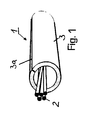
- Fig. 1 shows a perspective view of part of a according to the teaching of the invention manufactured optical cable.
- the optical cable 1 consists of the optical fibers 2 and the metal tube 3 surrounding the optical waveguide 2, which has a longitudinal weld 3a having.
- the space between the optical fibers 2 and the metal tube 3 can be with a so-called petroleum jelly must be filled in to prevent longitudinal water migration.
- the optical fibers 2 have a greater length than the metal tube 3, so they run wave helical or sinusoidal in the metal tube 3.
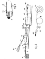
- Fig. 2 shows a side view of a manufacturing device.
- a tape supply at 4 referred to of which a metal strip 5, preferably a strip made of stainless steel is continuously subtracted.
- the band 5 is braked by means of a band brake 6.
- a Trimming shear 7 trims the metal strip 5 on its longitudinal edges, so that on the one hand always there is an equal bandwidth to the other metallic pure ribbon edges.
- the metal strip 5 is gradually formed into a slotted tube. In that yet open slotted tubes become optical fibers 9, which are drawn off from supply coils 10, introduced. With 11, a filling device is designated, which a petroleum jelly in the slot tube filled in.
- the slotted tube is by means of a laser welding head 12 on its band edges welded, and the welded tube 13 by means of a reducing device 14 for example, a drawing die or a so-called Turkish head in its diameter reduced.
- a reducing device 14 for example, a drawing die or a so-called Turkish head in its diameter reduced.
- a Collet trigger 15 applied to apply the forces required for pulling and shaping the metal strip 5 and the pulling down of the metal tube 13 necessary forces are by means of a Collet trigger 15 applied.
- Behind the collet trigger 15 is another Collet trigger 16 arranged.
- one second reducing device 17 is provided, either a drawing die or a Turkish head can be.
- a third reducing device 18 is arranged behind the collet trigger 16.
- the Pull-off force for the tube behind the third die 18 or the third Vietnamese head is achieved by a disc trigger 19 applied, around which the tube is wrapped in several turns is.
- the tube running off the disc take-off 19 is wound on a rewinder 20 wound up.
- the excess length of the optical waveguide 9 in the metal tube 13 is now generated in that the Metal tube 13 between the reducing device 18 and the disc trigger 19 elastic is stretched.
- the elastic stretch is removed on the disc trigger 20. Since the Optical waveguide 9 at the same speed as the elastically stretched metal tube 13 are subtracted, there is an excess length of when the elastic stretch is removed Optical waveguide 9 in the metal tube 13, which is dependent on the size of the weight 21.
- the take-off speed of the collet trigger 15 and 16 as well as the disc trigger 19 is regulated by so-called dancer devices, not shown.
- the percentage reduction of the metal tube 13 is preferably in the third reduction stage 18 greater than the sum of the percentage reductions in the metal tube 13 in the first and second reducing device 14 and 17.
- the drawing die or the die 22 is arranged in a holder 23, which in turn is in a Drawing die receptacle 24 is mounted to be longitudinally displaceable.
- a pipe guide 26 Located at the entrance of the bracket 23 a pipe guide 26.
- an opening 25 is provided in the holder 23, in which drawing oil can be filled into the holder 23.
- the holder 23 is resiliently mounted in the drawing die receptacle 24 via plate springs 27.
- the Disc springs 27 are preloaded when the metal tube 13 is pulled.
- the advantage of the resilient mounting of the holder 23 in the die holder 24 is in that if production is interrupted after resetting the metal tube 13 through the collet deductions for welding the weld seam of the metal tube 13 abrupt insertion of the drawing process at the reduction stages is avoided.
Landscapes
- Physics & Mathematics (AREA)
- Engineering & Computer Science (AREA)
- Manufacturing & Machinery (AREA)
- General Physics & Mathematics (AREA)
- Optics & Photonics (AREA)
- Manufacturing Of Electric Cables (AREA)
- Metal Extraction Processes (AREA)
- Optical Fibers, Optical Fiber Cores, And Optical Fiber Bundles (AREA)
Applications Claiming Priority (2)
| Application Number | Priority Date | Filing Date | Title |
|---|---|---|---|
| DE19816998 | 1998-04-17 | ||
| DE19816998A DE19816998A1 (de) | 1998-04-17 | 1998-04-17 | Verfahren zur Herstellung eines optischen Kabels |
Publications (2)
| Publication Number | Publication Date |
|---|---|
| EP0950907A2 true EP0950907A2 (fr) | 1999-10-20 |
| EP0950907A3 EP0950907A3 (fr) | 2000-01-19 |
Family
ID=7864801
Family Applications (1)
| Application Number | Title | Priority Date | Filing Date |
|---|---|---|---|
| EP99400699A Ceased EP0950907A3 (fr) | 1998-04-17 | 1999-03-19 | Procédé de fabrication d'un cable optique |
Country Status (5)
| Country | Link |
|---|---|
| US (1) | US6298542B1 (fr) |
| EP (1) | EP0950907A3 (fr) |
| CA (1) | CA2266816A1 (fr) |
| DE (1) | DE19816998A1 (fr) |
| NO (1) | NO991843L (fr) |
Cited By (1)
| Publication number | Priority date | Publication date | Assignee | Title |
|---|---|---|---|---|
| CN105032965A (zh) * | 2015-08-10 | 2015-11-11 | 西安西古光通信有限公司 | 一种金属复合带纵包成型装置 |
Families Citing this family (1)
| Publication number | Priority date | Publication date | Assignee | Title |
|---|---|---|---|---|
| EP3797891B1 (fr) * | 2019-09-30 | 2023-08-02 | Nexans | Procédé de fabrication en continu de profilés creux, ondulés par sections, minces, de petit diamètre en metal non ferreux |
Family Cites Families (21)
| Publication number | Priority date | Publication date | Assignee | Title |
|---|---|---|---|---|
| US2110965A (en) * | 1934-07-02 | 1938-03-15 | Tubus A G | Reducing the diameter of hollow metal articles |
| US3207651A (en) * | 1961-07-13 | 1965-09-21 | Procter & Gamble | Apparatus for making tubing from a continuous web |
| US3332138A (en) * | 1965-08-11 | 1967-07-25 | Gen Cable Corp | Method and apparatus for making precision sized tubing |
| DE1614657C3 (de) * | 1967-11-22 | 1975-03-27 | Siemens Ag, 1000 Berlin Und 8000 Muenchen | Verfahren zur Verkleinerung des Spaltes zwischen Hüllrohr und Brennstoffüllung von Kernreaktorbrennstäben |
| US3668916A (en) * | 1970-01-19 | 1972-06-13 | Wean Ind Inc | Drawing of metal tubing |
| DE2401345A1 (de) * | 1974-01-09 | 1975-07-10 | Mannesmann Roehren Werke Ag | Zieh-streckverfahren zur herstellung langer rohre und vorrichtung zur durchfuehrung des verfahrens |
| US3928997A (en) * | 1975-03-28 | 1975-12-30 | Olin Corp | Method and apparatus for producing corrugated tubing |
| US4090381A (en) * | 1975-06-23 | 1978-05-23 | Mikhail Vladimirovich Babasov | Device for drawing-off and straightening cylindrically shaped stock |
| US4079616A (en) * | 1976-03-19 | 1978-03-21 | Viktor Afanasievich Zazimko | Draw bench for producing cylindrical tubular items by drawing |
| IT1115656B (it) * | 1977-05-04 | 1986-02-03 | Pirelli | Metodo di produzione di elementi componenti cavi di telecomunicazione e impianto atto a realizzarlo |
| DE2851800A1 (de) * | 1978-11-30 | 1980-06-12 | Kabel Metallwerke Ghh | Verfahren und vorrichtung zur herstellung eines vieladrigen nachrichtenkabels |
| US4291565A (en) * | 1979-08-22 | 1981-09-29 | Asa Enterprises, Inc. | Wire drawing device |
| US4441830A (en) * | 1982-03-29 | 1984-04-10 | Ncr Corporation | Printing solenoid |
| DE3612805C2 (de) * | 1986-04-16 | 1995-06-14 | Kabelmetal Electro Gmbh | Verfahren und Vorrichtung zum Herstellen eines im Querschnitt hohlzylinderförmigen langgestreckten Gutes |
| US4759487A (en) * | 1987-03-09 | 1988-07-26 | K-Tube Corporation | Apparatus for continuous manufacture of armored optical fiber cable |
| FR2650081B1 (fr) * | 1989-07-24 | 1991-10-04 | Foptica | Procede et appareil de fabrication de modules optiques |
| KR960003727B1 (ko) * | 1989-12-05 | 1996-03-21 | 니홍 고오강 가부시끼가이샤 | 금속관 피복 광 파이버 케이블의 제조장치 및 제조 방법 |
| DE4118004A1 (de) * | 1991-06-01 | 1992-12-03 | Kabelmetal Electro Gmbh | Verfahren zur herstellung von mit einer schicht aus aluminium plattiertem strangfoermigem gut |
| DE4434133A1 (de) * | 1994-09-24 | 1996-03-28 | Kabelmetal Electro Gmbh | Verfahren zur Herstellung eines optischen Kabels aus einem Metallrohr |
| DE4434134A1 (de) * | 1994-09-24 | 1996-03-28 | Kabelmetal Electro Gmbh | Verfahren zur Herstellung eines längsnahtgeschweißten Metallrohres |
| DE19501945A1 (de) * | 1995-01-24 | 1996-07-25 | Alcatel Kabel Ag | Verfahren zur Herstellung längsnahtgeschweißter Metallrohre |
-
1998
- 1998-04-17 DE DE19816998A patent/DE19816998A1/de not_active Withdrawn
-
1999
- 1999-03-19 EP EP99400699A patent/EP0950907A3/fr not_active Ceased
- 1999-04-12 CA CA002266816A patent/CA2266816A1/fr not_active Abandoned
- 1999-04-16 NO NO991843A patent/NO991843L/no not_active Application Discontinuation
- 1999-04-16 US US09/292,956 patent/US6298542B1/en not_active Expired - Fee Related
Cited By (1)
| Publication number | Priority date | Publication date | Assignee | Title |
|---|---|---|---|---|
| CN105032965A (zh) * | 2015-08-10 | 2015-11-11 | 西安西古光通信有限公司 | 一种金属复合带纵包成型装置 |
Also Published As
| Publication number | Publication date |
|---|---|
| DE19816998A1 (de) | 1999-10-21 |
| US6298542B1 (en) | 2001-10-09 |
| EP0950907A3 (fr) | 2000-01-19 |
| CA2266816A1 (fr) | 1999-10-17 |
| NO991843D0 (no) | 1999-04-16 |
| NO991843L (no) | 1999-10-18 |
Similar Documents
| Publication | Publication Date | Title |
|---|---|---|
| EP0703017B1 (fr) | Procédé de fabrication de tuyaux métalliques soudés longitudinalement | |
| EP0703478B1 (fr) | Procédé de fabrication d'un câble optique d'un tuyau métallique | |
| WO1998006155A1 (fr) | Procede de torsadage d'au moins deux fils et dispositif correspondant | |
| DE3808037C2 (de) | Verfahren zur Herstellung eines optischen Kabels und Vorrichtung zu dessen Durchführung | |
| EP0313896A1 (fr) | Procédé et dispositif pour la fabrication de câbles optiques | |
| DE69733053T2 (de) | Herstellungsverfahren eines optischen Kabels mit SZ-Führungsnuten | |
| DE69225531T2 (de) | Verfahren und Vorrichtung zur Herstellung eines faseroptischen Kabels | |
| EP1345057A2 (fr) | Méthode de fabrication pour un câble à fibres optiques | |
| EP0007473A1 (fr) | Dispositif de câblage SZ d'âmes de câbles de courant fort avec une section transversale du conducteur en forme d'un secteur | |
| DE19741934C2 (de) | Vorrichtung und Verfahren zum Regeln des Stauchens eines Metallröhrchens mit mindestens einem innenliegenden Lichtwellenleiter | |
| DE2508385A1 (de) | Vorrichtung zum verdrehen eines leiters | |
| CH634119A5 (de) | Verfahren und vorrichtung zur kontinuierlichen herstellung von strangfoermigem gut durch verseilung von formstraengen. | |
| EP1103013B1 (fr) | Procede pour fabriquer un cable optique avec une surlongueur des guides d'ondes optiques | |
| DE4323649A1 (de) | Verfahren zur Herstellung eines schraubenlinien- oder ringförmig gewellten Metallrohres | |
| EP0962801A2 (fr) | Dispositif pour fabriquer une cable à fibre optique | |
| DE19816998A1 (de) | Verfahren zur Herstellung eines optischen Kabels | |
| DE3023507A1 (de) | Vorrichtung zum ziehen von strangfoermigem gut | |
| AT5699U1 (de) | Drahtseil mit mehreren litzen sowie verfahren und vorrichtung zum einbringen einer stützlitze | |
| DE69526125T2 (de) | Verfahren und Vorrichtung zur Herstellung von schraubenförmigen Gegenständen | |
| DE877327C (de) | Verfahren zum Befestigen einer Zugvorrichtung an einem Metallrohr, insbesondere beim Niederziehen von Metallrohren zum Ummanteln elektrischer Kabel | |
| EP0842716A2 (fr) | Procédé et dispositif de fabrication de tubes métalliques de grande longueur | |
| DE2641864C2 (de) | Verfahren und Vorrichtung zur kontinuierlichen Herstellung von Drähten aus einer Aluminiumseele und einer Kupferumhüllung | |
| DE3422803C2 (fr) | ||
| DE2153934A1 (de) | Vorrichtung zur herstellung duennwandiger rohre | |
| AT394467B (de) | Verfahren und vorrichtung zum aufbringen einer aus einzeldraehten bestehenden flexiblen metallischen abschirmung um eine kabelseele |
Legal Events
| Date | Code | Title | Description |
|---|---|---|---|
| PUAI | Public reference made under article 153(3) epc to a published international application that has entered the european phase |
Free format text: ORIGINAL CODE: 0009012 |
|
| AK | Designated contracting states |
Kind code of ref document: A2 Designated state(s): AT CH DE DK ES FI FR GB GR IT LI NL SE |
|
| AX | Request for extension of the european patent |
Free format text: AL;LT;LV;MK;RO;SI |
|
| PUAL | Search report despatched |
Free format text: ORIGINAL CODE: 0009013 |
|
| 17P | Request for examination filed |
Effective date: 19991103 |
|
| RTI1 | Title (correction) |
Free format text: METHOD OF FABRICATING AN OPTICAL CABLE |
|
| AK | Designated contracting states |
Kind code of ref document: A3 Designated state(s): AT BE CH CY DE DK ES FI FR GB GR IE IT LI LU MC NL PT SE |
|
| AX | Request for extension of the european patent |
Free format text: AL;LT;LV;MK;RO;SI |
|
| RTI1 | Title (correction) |
Free format text: METHOD OF FABRICATING AN OPTICAL CABLE |
|
| AKX | Designation fees paid |
Free format text: AT CH DE DK ES FI FR GB GR IT LI NL SE |
|
| RAP1 | Party data changed (applicant data changed or rights of an application transferred) |
Owner name: NEXANS |
|
| 17Q | First examination report despatched |
Effective date: 20030514 |
|
| STAA | Information on the status of an ep patent application or granted ep patent |
Free format text: STATUS: THE APPLICATION HAS BEEN REFUSED |
|
| 18R | Application refused |
Effective date: 20030719 |