EP0950914B1 - Brillenbügel - Google Patents
Brillenbügel Download PDFInfo
- Publication number
- EP0950914B1 EP0950914B1 EP99106152A EP99106152A EP0950914B1 EP 0950914 B1 EP0950914 B1 EP 0950914B1 EP 99106152 A EP99106152 A EP 99106152A EP 99106152 A EP99106152 A EP 99106152A EP 0950914 B1 EP0950914 B1 EP 0950914B1
- Authority
- EP
- European Patent Office
- Prior art keywords
- temple
- component
- tip
- seat
- elastically deformable
- Prior art date
- Legal status (The legal status is an assumption and is not a legal conclusion. Google has not performed a legal analysis and makes no representation as to the accuracy of the status listed.)
- Expired - Lifetime
Links
- 238000003780 insertion Methods 0.000 claims description 4
- 230000037431 insertion Effects 0.000 claims description 4
- 230000003993 interaction Effects 0.000 claims description 4
- 239000000463 material Substances 0.000 claims description 3
- 230000005489 elastic deformation Effects 0.000 claims description 2
- PXHVJJICTQNCMI-UHFFFAOYSA-N Nickel Chemical compound [Ni] PXHVJJICTQNCMI-UHFFFAOYSA-N 0.000 description 2
- 230000000295 complement effect Effects 0.000 description 2
- 239000002184 metal Substances 0.000 description 2
- 229910052751 metal Inorganic materials 0.000 description 2
- 206010020751 Hypersensitivity Diseases 0.000 description 1
- 208000027418 Wounds and injury Diseases 0.000 description 1
- 230000007815 allergy Effects 0.000 description 1
- 230000006378 damage Effects 0.000 description 1
- 230000000694 effects Effects 0.000 description 1
- 229920002457 flexible plastic Polymers 0.000 description 1
- 208000014674 injury Diseases 0.000 description 1
- 230000000670 limiting effect Effects 0.000 description 1
- 238000004519 manufacturing process Methods 0.000 description 1
- 238000012986 modification Methods 0.000 description 1
- 230000004048 modification Effects 0.000 description 1
- 229910052759 nickel Inorganic materials 0.000 description 1
- 238000000926 separation method Methods 0.000 description 1
Images






Classifications
-
- G—PHYSICS
- G02—OPTICS
- G02C—SPECTACLES; SUNGLASSES OR GOGGLES INSOFAR AS THEY HAVE THE SAME FEATURES AS SPECTACLES; CONTACT LENSES
- G02C5/00—Constructions of non-optical parts
- G02C5/008—Spectacles frames characterized by their material, material structure and material properties
-
- G—PHYSICS
- G02—OPTICS
- G02C—SPECTACLES; SUNGLASSES OR GOGGLES INSOFAR AS THEY HAVE THE SAME FEATURES AS SPECTACLES; CONTACT LENSES
- G02C5/00—Constructions of non-optical parts
- G02C5/006—Collapsible frames
-
- G—PHYSICS
- G02—OPTICS
- G02C—SPECTACLES; SUNGLASSES OR GOGGLES INSOFAR AS THEY HAVE THE SAME FEATURES AS SPECTACLES; CONTACT LENSES
- G02C5/00—Constructions of non-optical parts
- G02C5/02—Bridges; Browbars; Intermediate bars
- G02C5/10—Intermediate bars or bars between bridge and side-members
-
- G—PHYSICS
- G02—OPTICS
- G02C—SPECTACLES; SUNGLASSES OR GOGGLES INSOFAR AS THEY HAVE THE SAME FEATURES AS SPECTACLES; CONTACT LENSES
- G02C5/00—Constructions of non-optical parts
- G02C5/22—Hinges
- G02C5/2272—Hinges without well-defined pivot axis
-
- G—PHYSICS
- G02—OPTICS
- G02C—SPECTACLES; SUNGLASSES OR GOGGLES INSOFAR AS THEY HAVE THE SAME FEATURES AS SPECTACLES; CONTACT LENSES
- G02C2200/00—Generic mechanical aspects applicable to one or more of the groups G02C1/00 - G02C5/00 and G02C9/00 - G02C13/00 and their subgroups
- G02C2200/04—Junctions between frame elements having a click function
-
- G—PHYSICS
- G02—OPTICS
- G02C—SPECTACLES; SUNGLASSES OR GOGGLES INSOFAR AS THEY HAVE THE SAME FEATURES AS SPECTACLES; CONTACT LENSES
- G02C2200/00—Generic mechanical aspects applicable to one or more of the groups G02C1/00 - G02C5/00 and G02C9/00 - G02C13/00 and their subgroups
- G02C2200/08—Modular frames, easily exchangeable frame parts and lenses
-
- G—PHYSICS
- G02—OPTICS
- G02C—SPECTACLES; SUNGLASSES OR GOGGLES INSOFAR AS THEY HAVE THE SAME FEATURES AS SPECTACLES; CONTACT LENSES
- G02C2200/00—Generic mechanical aspects applicable to one or more of the groups G02C1/00 - G02C5/00 and G02C9/00 - G02C13/00 and their subgroups
- G02C2200/16—Frame or frame portions made from rubber
Definitions
- the present invention relates to a temple for eyeglasses.
- Conventional eyeglasses are currently usually constituted by a front and by a temple which are mutually connected by means of an adapted hinge.
- the hinge is usually constituted by a body which has a first component associated with the front and a second component associated with the temple; the first and second components are mutually rotatably articulated by using a suitable connection pivot, which is usually constituted by a metal screw.
- the eyeglasses are used by children, there is the risk that they might swallow small components such as the screws, and the child might force the separation of the components of the eyeglasses and therefore of the temple from the front; it is also noted that in the case of a child the need is strongly felt to avoid, when wearing the eyeglasses, having metal parts in internal regions of the eyeglasses and particularly at the temple in the part that is adjacent to the temple region of the head, which can sometimes cause injury in case of impact.
- eyeglasses for children which are monolithically made of flexible plastics; this solution, however, is not ideal, since in any case the temples, since they are not preformed, do not allow to wear the eyeglasses unless there are laces or elastic elements which are engaged, to the tip of the temple; additionally, the characteristics of said temple allow no adjustment of the frame and therefore make it impossible to adapt it to the consumer's face.
- the aim of the present invention is to solve the above-mentioned problems, eliminating the drawbacks of the cited prior art, by providing eyeglasses which have optimum fit and comfort for the user also in the case of a child.
- an object of the present invention is to provide eyeglasses which do not have minute components which can be separated from them and might therefore be swallowed.
- Another object of the present invention is to provide eyeglasses having a temple which can be temporarily connected to the front stably and easily.
- Another object of the present invention is to provide eyeglasses in which the temple can be modeled according to the features of the user.
- Another object of the present invention is to provide eyeglasses whose temple can be easily replaced.
- a further object of the present invention is to provide eyeglasses in which an optimum hinge effect is provided between the temple and the front to allow both extra-wide opening beyond the position for normal use and folding of temples against the front.
- a still further important object of the present invention is to provide eyeglasses which allow to simplify the assembly cycle.
- Another object of the present invention is to provide eyeglasses which are structurally simple and have low manufacturing costs.
- a temple for eyeglasses as defined in the appended claim 1, and which, is constituted by at least one rigid support which is associated with a front and with which at least one softer element, adapted to act as a hinge, is associated.
- United States Patent 5059017 discloses a temple for eyeglasses of the same kind of the one set forth in the preamble of claim 1.
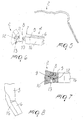
- the reference numeral 1 designates a pair of eyeglasses, shown schematically by considering a front 2 with whose ends a temple, designated by the reference numeral 3, is associable.
- the temple 3 is constituted by at least one rigid support 4 which is associable at the front 2.
- the support 4 is divided into a first component 5, which has means for temporary connection to the front 2, and into a separate second component 6, which is laterally adjacent to the preceding one and is longer so as to affect the region of the auricle of the user.
- the first component 5 further has a first tip 7 which is shaped complementarily to the corresponding end of the front 2; the detachable connection means protrude from it and are constituted by a tab 8 which is substantially shaped like a parallelepiped and in which at least one axial slot 9 is defined so as to form a pair of wings, at least one of which has a tooth 10 arranged along an axis which lies transversely to the slot 9.
- a first seat 11 which is shaped complementarily to the tab 8 and therefore has a complementary tooth 12 which engages the tooth 10 during the insertion of the tab, whose wings undergo an elastic deformation, compressing during insertion and returning to the normal position once the tab has been inserted, thus allowing interaction between the complementary tooth and the tooth.
- a second seat 13 is connected to the first seat 11 and is preferably formed along a perpendicular axis with respect to the axis of the first seat; seat 13 is meant to allow the access of a tool, such as for example a screwdriver, which allows to access the tooth 10 and therefore to compress the wings of the tab 8 in order to allow disengagement from the first seat 11.
- a tool such as for example a screwdriver
- the first component 5 has a second tip 14 which is laterally adjacent to a complementarily shaped third tip 15 of the second component 6, which is associated with the first component 5 by means of at least one softer element 16 which is preferably arranged at the surface that is directed toward the temple of the user's head.
- element 16 has the same height as the first and second components, affects the entire length of the second component 6 and partially affects the length of the first component 5 up to the vicinity of the means for detachable connection to the front.
- the element 16 is associated with the first and second components so that the second tip 14 and the third tip 15 approximately mate; the element 16, together with the first and second components, accordingly forms a hinge which allows to keep the temple 3 in the open condition when not in use and at the same time allows both extra-wide opening, shown in Figures 5 and 8, or temporary folding, shown in Figures 2 and 4, against the front 2.
- the invention has achieved the intended aim and objects, a temple having been provided which allows to give the eyeglasses optimum fit and comfort for the user also in the case of a child.
- the temple has no small components, such as screws, and therefore the eyeglasses have nothing that makes them unsuitable for use on the part of a child; moreover, the resulting hinge element is structurally simple and the temple also has good mechanical characteristics, by virtue of the presence of the rigid components, and good comfort characteristics, by virtue of the presence of the soft parts.
- Comfort is further increased by the possibility to achieve extra-wide opening of the temple beyond the condition of normal use and by the possibility to fold the temples against the front.
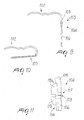
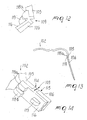
- Figures 9 to 15 illustrate a second embodiment of a temple 103, which is constituted by a rigid support 104 which is again constituted by a first component 105 and by a second component 106 which are mutually separate; the first component 105 can be associated, or is associated, at an end of a front 102.
- the second tip 114 of the first component 105 is spaced with respect to the third tip 115 of the second component 106 and the stem 117 of a softer element 116, suitable to act as a hinge, can be arranged in the interspace between said tips.
- the element 116 affects approximately the entire length of the second component 106 and partially affects the length of the first component 105; said stem 117 has, in the interspace between the second tip 114 and the third tip 115, an axial slot 109 which is accordingly arranged at right angles to the longitudinal axis of the first and second components; for graphic reasons the slot has been exaggerated in the drawings with respect to the real situation.
- the slot 109 acts as a hinge, allowing, as shown in Figures 10, 12, 13 and 15, to fold the temple 103 against the front 102 or to open it extra-wide.
- means for guiding and temporarily locking the position of the second component 106 with respect to the first component 105 are also provided; said means are constituted by two first raised portions 118a, 118b, which are formed longitudinally and to the sides of the end of the element 116 that lies above the first component 105, and by a second raised portion 119 which also protrudes from the element 116 at a region that lies above the second component 106.
- the second raised portion 119 is shaped complementarily to the interspace provided between the first raised portions 118a and 118b and is arranged at a such distance from them that an initial rotation of the temple 103 to fold it against the front 102 produces a partial interaction of the second raised portion 119 in the interspace between the first raised portions 118a and 118b.
- This embodiment too, achieves the intended aim and objects.
- Figures 16 to 22 are views of a third embodiment of the temple designated by the reference numeral 203, which is again constituted by a rigid support 204 with which a softer element 216 is associated; the tip of the softer element has means for detachable connection to a front 202 which are constituted by a tab 208 which is substantially arrow-shaped and can be detachably inserted in a complementarily shaped first seat 211 formed in the front 202.
- the element 216 is therefore longer than the support 204 and directly interacts with the temples of the user's head.
- the first tip 207 is arranged approximately in abutment against the front; extra-wide opening and flexing against the front 202, as shown in Figures 18, 20 and 22, are allowed in any case.
- the distance between the first tip 207 of the support 204 and the facing surface of the front 202 is such that a chosen rotation of the temple in the extra-wide opening condition is matched by an abutment interaction between said first tip 207 and the surface of the front 202, thus constituting a stroke limiter.
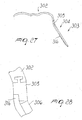
- Figures 23 to 28 illustrate a fourth embodiment of a temple 303 which is constituted by a rigid support 304 which is in turn composed of a first component 305, provided with means for temporary connection to the front 302, and of a second component 306, which protrudes toward the auricle of the user.
- the means for connection to the front are advantageously constituted by a tab 308 which has a T-shaped transverse cross-section and can be slidingly arranged at a complementarily shaped seat formed at one end of said front.
- the first and second components are associated at a softer element 316 which is associated therewith so that the second tip 314 and the third tip 315 of the first and second components, respectively, are approximately mutually adjacent.
- the combination of the first component and of the second component of the element 316 allows to form a hinge which in turn allows the temple to achieve both extra-wide opening and repositioning against the front 302.
- Figures 29 to 34 illustrate a fifth embodiment of a temple 403, which is constituted by a rigid support 404 which is in turn composed of a first component 405, which is associated or associable with a front 402, and of a separate second component 406.
- the second tip 414 of the first component 405 and the third tip 415 of the second component 406 are mutually spaced so as to allow to insert between them the stem 417 of an element 416 which is softer than the first and second components and is adapted to act as a hinge.
- An axial slot 409 is in fact provided at the stem 417, and allows, when it is opened, to position the temple 403 against the front 402 and, when it is closed, to provide extra-wide opening.
- Figures 35 to 40 illustrate a sixth embodiment of a temple 503 in which, differently from the preceding case, the stem 517 protrudes beyond the surfaces of the first component 505 and of the second component 506 which do not interact with the element 516; said stem accordingly has a substantially T-shaped transverse cross-section, whose wings 520a and 520b are variously shaped and respectively wrap around the second tip 514 of the first component 505 and the third tip 515 of the second component 506.
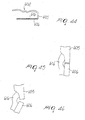
- Figures 41 to 48 illustrate a seventh embodiment of a temple 603 which is again constituted by a rigid support 604 which is in turn composed of a first component 605 and of a second component 606 which are mutually separate and are adjacent respectively at the second tip 614 and at the third tip 615.
- the first and second components are mutually associated by means of a softer element 616 which is adapted to act as a binge and is separated from the first and second components at the region of the second and third tips.
- the element 616 therefore has, in the region, an arc-like shape with the concavity directed toward the temple of the user's head; this configuration allows to improve the movement conditions of the temple and therefore to achieve, in an optimum manner, both extra-wide opening and closure against the front 602.
- a tab 608 is provided at, and protrudes from, the first component 605 and has, at one end, an axial slot 609 provided along a plane which is parallel to the outer lateral surface of the rigid support 604, so as to form a pair of wings; the lateral one of the wings is directed toward the temple of the user's head and has a tooth 610 suitable to temporarily engage at a complementarily shaped tooth 612 formed within a first seat 611 formed at the facing end of the front 602.
Landscapes
- Physics & Mathematics (AREA)
- Health & Medical Sciences (AREA)
- General Physics & Mathematics (AREA)
- Ophthalmology & Optometry (AREA)
- Optics & Photonics (AREA)
- Eyeglasses (AREA)
- Preparation Of Compounds By Using Micro-Organisms (AREA)
Claims (20)
- Ein Bügel (3, 103, 203, 303, 403, 503, 603) für Brillengläser (1), die mit einer Vorderseite (2, 102, 202, 302, 402, 502, 602) verknüpft ist, und der mindestens einen starren Träger (4, 104, 204, 304, 404, 604) und mindestens ein flexibles Element (16, 116, 216, 316, 416, 516, 616) umfasst, das aus einem weichen, elastisch verformbaren Material besteht, dadurch gekennzeichnet, dass das flexible Element (16, 116, 216, 316, 416, 516, 616) am starren Träger des Bügels an seiner Oberfläche befestigt ist, die in Richtung der Schläfe des Kopfes des Benutzers gerichtet ist und einen Vorderseite-Endabschnitt aufweist, der ein Mittel für das vorübergehende Anschließen an die Vorderseite umfasst, so dass das flexible Element ein Gelenk bildet, das dem Bügel (3, 103, 203, 303, 403, 503, 603) erlaubt, im offenen Zustand zu bleiben, wenn er nicht verwendet wird, und das die sehr weite Öffnung oder das vorübergehende Falten gegen die Brillengläser-Vorderseite (2, 102, 202, 302, 402, 502, 602) erlaubt.
- Der Bügel (3, 103, 303, 403, 503, 603) nach Anspruch 1, dadurch gekennzeichnet, dass der zumindest eine starre Träger (4, 104, 304, 404, 604) wiederum in einen ersten Bestandteil (5, 105, 305, 405, 505, 605), der das Mittel für das vorübergehende Anschließen an die Vorderseite (2, 102, 302, 402, 502, 602) bildet, und in einen getrennten zweiten Bestandteil (6, 106, 306, 406, 506, 606) unterteilt ist, der seitlich angrenzend am ersten Bestandteil (5, 105, 305, 405, 505, 605) angeordnet ist und der länger als das erste Element ist.
- Der Bügel (3, 103, 303, 403, 503, 603) nach Anspruch 2, dadurch gekennzeichnet, dass der erste Bestandteil (5, 105, 305, 405, 505, 605) eine erste Spitze (7) hat, die komplementär zu einem entsprechenden Ende der Vorderseite (2, 102, 302, 402, 502, 602) geformt ist, wobei das vorübergehende Anschlussmittel daraus vorragt und durch mindestens einen Lappen (8, 608) gebildet ist, der wie ein Parallelepiped geformt ist und auf dem mindestens ein axialer Schlitz (9, 609) bereitgestellt wird, um ein Flügelpaar zu bilden, von dem mindestens ein Flügel einen Zahn (10, 610) hat, der entlang einer Achse angeordnet ist, die transversal zum Schlitz (9, 609) liegt, wobei ein erster Sitz (11, 611) an der Spitze der Vorderseite (2, 102, 302, 402, 502, 602) ausgebildet ist, wobei der Sitz komplementär mit dem Lappen (8, 608) ausgebildet ist und über einen komplementär geformten Zahn (12, 612) verfügt, der während der Einfügung des Lappens (8, 608) selektiv in den Zahn (10, 610) eingreift, wobei seine Flügel einer elastischen Verformung unterzogen werden, indem sie während der Einfügung komprimiert werden und in die normale Stellung zurücktreten, wenn der Lappen (8, 608) einmal eingefügt wurde.
- Der Bügel (3, 103, 303, 403, 503, 603) nach Anspruch 3, dadurch gekennzeichnet, dass ein zweiter Sitz (13) mit dem ersten Sitz (11, 611) verbunden ist und an einer Achse entlang ausgebildet ist, die senkrecht in Bezug zur Achse des ersten Sitzes (11; 611) liegt; wobei der zweite Sitz (13) den Zugriff auf ein Werkzeug, zum Beispiel einen Schraubenzieher, erlaubt, damit die Flügel des Lappens (8, 608) komprimiert werden, um das Entkoppeln aus dem ersten Sitz (11, 611) zu erlauben.
- Der Bügel (3, 103, 303, 403, 503, 603) nach Anspruch 4, dadurch gekennzeichnet, dass der erste Bestandteil (5, 105, 305, 405, 505, 605) eine zweite Spitze (14, 114, 314, 414, 514, 614) hat, die seitlich angrenzend an einer komplementär geformten dritten Spitze (15, 115, 315, 415, 515, 615) des zweiten Bestandteils (6, 106, 306, 406, 506, 606) ist, wobei der erste und der zweite Bestandteil mithilfe des elastisch verformbaren Elements (16, 116, 316, 416, 516, 616) wechselseitig verknüpft sind.
- Der Bügel (3, 103, 303, 403, 503, 603) nach Anspruch 5, dadurch gekennzeichnet, dass das elastisch verformbare Element (16, 116, 316, 416, 516, 616) so hoch wie der erste (5, 105, 305, 405, 505, 605) und der zweite (6, 106, 306, 406, 506, 606) Bestandteil ist, sich auf die gesamte Länge des zweiten Bestandteils (6, 106, 306, 406, 506, 606) auswirkt und sich teilweise auf die Länge des ersten Bestandteils (5, 105, 305, 405, 505, 605) bis in die Nähe des Mittels für das vorübergehende Anschließen an der Vorderseite (2, 102, 302, 402, 502, 602) auswirkt.
- Der Bügel (3, 303, 603) nach Anspruch 5, dadurch gekennzeichnet, dass das elastisch verformbare Element (16, 316, 616) mit dem ersten (5, 305, 605) und dem zweiten (6, 306, 606) Bestandteil verknüpft wird, so dass die zweite (14, 314, 614) und die dritte (15, 315, 615) Spitze annähernd zusammenpassen, wobei das Element (16, 316, 616) und der erste (5, 305, 605) und der zweite (6, 306, 606) Bestandteil das Gelenk bilden.
- Der Bügel (3, 103, 403, 503) nach Anspruch 5, dadurch gekennzeichnet, dass die zweite Spitze (14, 114, 414, 514) des ersten Bestandteils (5, 105, 405, 505) in Bezug auf die dritte Spitze (15, 115, 415, 515) des zweiten Bestandteils (6, 106, 406, 506) beabstandet ist, wobei ein Heck (117, 417, 517) des elastisch verformbaren Elements (16, 116, 416, 516) in einem dazwischen bestimmten Zwischenraum angeordnet werden kann.
- Der Bügel (3, 103, 403, 503) nach Anspruch 8, dadurch gekennzeichnet, dass das Heck (117, 417, 517) in dem Zwischenraum zwischen der zweiten (14, 114, 414, 514) und der dritten (15, 115, 415, 515) Spitze einen axialen Schlitz (109, 409) hat, der in rechten Winkeln zu einer Längsachse des ersten (5, 105, 405, 505) und zweiten (6, 106, 406, 506) Bestandteils angeordnet ist und der als Gelenk wirkt .
- Der Bügel (103) nach Anspruch 9, dadurch gekennzeichnet, dass Mittel zum Führen und vorübergehenden Verschließen der Stellung des zweiten Bestandteils (106) in Bezug auf den ersten Bestandteil (105) am elastisch verformbaren Element (116) bereitgestellt werden, wobei die Mittel zum Führen und Verschließen durch zwei erste erhöhte Abschnitte (118a, 118b) gebildet werden, die längs und an den Seiten des Endes des Elements (116) ausgebildet sind, das über dem ersten Bestandteil (105) liegt, und durch einen zweiten erhöhten Abschnitt (119) gebildet werden, der an einem Bereich, der über dem zweiten Bestandteil (106) liegt, aus dem elastisch verformbaren Element (116) vorragt.
- Der Bügel (103) nach Anspruch 10, dadurch gekennzeichnet, dass der zweite erhöhte Abschnitt (119) komplementär mit dem zwischen den ersten erhöhten Abschnitten (118a, 118b) bereitgestellten Zwischenraum geformt ist und in einer Entfernung zwischen den ersten erhöhten Abschnitten (118a, 118b) derart angeordnet ist, dass einer anfänglichen Drehung des Bügels (103) für sein Falten gegen die Vorderseite (102) ein Teileingriff des zweiten erhöhten Abschnitts (119) in den Zwischenraum folgt, der zwischen den ersten erhöhten Abschnitten (118a, 118b) bereitgestellt wird.
- Der Bügel (103) nach Anspruch 11, dadurch gekennzeichnet, dass die erste erhöhten Abschnitte (118a, 118b) und der zweite erhöhte Abschnitt (119) geeignet sind, um den Bügel (103) während des Verschließens zu führen und um eine zeitweilige Verriegelung der Drehung des zweiten Bestandteils (106) zu erreichen, wenn der zweite erhöhte Abschnitt (119) gegen die Oberfläche des Elements (116) stößt, die zwischen den ersten erhöhten Abschnitten (118a, 118b) bereitgestellt wird.
- Der Bügel (203) nach Anspruch 1, dadurch gekennzeichnet, dass der Vorderseite-Endabschnitt des elastisch verformbaren Elements (216) über ein Mittel zum lösbaren Anschluss an die Vorderseite (202) verfügt, wobei das Mittel durch einen pfeilförmigen Lappen (208) gebildet wird, der abnehmbar in einen in der Vorderseite (202) ausgebildete komplementär geformten ersten Sitz (211) eingefügt werden kann.
- Der Bügel (203) nach Anspruch 13, dadurch gekennzeichnet, dass das elastisch verformbare Element (216) länger ist als der Träger (204) und direkt mit den Schläfen des Kopfes des Benutzers zusammenwirkt, wobei die Spitze (207) des Trägers (204) annähernd in Anstoßung gegen die Vorderseite (202) angeordnet ist, wenn der Bügel (203) einmal mit der Vorderseite (202) verknüpft wurde .
- Der Bügel (203) nach Anspruch 14, dadurch gekennzeichnet, dass der Abstand zwischen der Spitze (207) des Trägers (204) und einer gegenüberliegenden Oberfläche der Vorderseite (202) derart ist, dass eine ausgesuchte Drehung des Bügels (203) in einem sehr weiten Öffnungszustand durch eine Anstoßung-Wechselwirkung zwischen der Spitze (207) und der Oberfläche der Vorderseite (202) entsprochen wird, womit eine Hubbegrenzung gebildet wird.
- Der Bügel (303) nach Anspruch 2, dadurch gekennzeichnet, dass das Mittel zur vorübergehenden Verbindung mit der Vorderseite (302) durch einen Lappen (308) gebildet wird, der einen T-förmigen Querschnitt hat und der gleitend an einem komplementär geformten Sitzf angeordnet werden kann, der an einem Ende der Vorderseite (302) ausgebildet ist.
- Der Bügel (503) nach Anspruch 9, dadurch gekennzeichnet, dass das Heck (517) über die seitlichen Oberflächen des ersten (505) und des zweiten (506) Bestandteils hinausragt, die nicht mit dem Element (516) zusammenwirken, wobei das Heck (517) einen T-förmigen Querschnitt hat, dessen verschiedenartig geformte Enden (520a, 520b) jeweils die zweite Spitze (514) des ersten Bestandteils (505) und die dritte Spitze (515) des zweiten Bestandteils (506) umgeben.
- , Der Bügel (603) nach Anspruch 5, dadurch gekennzeichnet, dass das elastisch verformbare Element (616) in dem Bereich der zweiten (614) und der dritten (615) Spitze vom ersten (605) und zweiten (606) Bestandteil beabstandet ist.
- Der Bügel (603) nach Anspruch 18, dadurch gekennzeichnet, dass das elastisch verformbare Element (616) in dem Bereich der zweiten (614) und dritten (615) Spitze des ersten (605) und des zweiten (606) Bestandteils bogenförmig ist, wobei die konvexe Form in Richtung der Schläfe des Kopfes des Benutzers gerichtet ist.
- Der Bügel (603) nach Anspruch 19, dadurch gekennzeichnet, dass am ersten Bestandteil (605) ein Lappen (608) bereitgestellt wird und daraus vorragt, und der an einem Ende einen axialen Schlitz (609) hat, der entlang einer Ebene gebildet ist, die parallel zur äußeren seitlichen Oberfläche des starren Trägers (604) liegt, so dass ein Flügelpaar gebildet wird, dessen seitlicher Flügel in Richtung der Schläfe des Kopfes des Benutzers gerichtet ist und einen Zahn (610) hat, der geeignet ist, um vorübergehend mit einem komplementär geformten Zahn (612) in Eingriff zu stehen, der innerhalb eines ersten Sitzes (611) ausgebildet ist, der an dem gegenüberliegenden Ende der Vorderseite (602) bereitgestellt wird.
Applications Claiming Priority (2)
| Application Number | Priority Date | Filing Date | Title |
|---|---|---|---|
| IT98TV000056A ITTV980056A1 (it) | 1998-04-15 | 1998-04-15 | Struttura di astina, particolarmente per occhiali |
| ITTV980056 | 1998-04-15 |
Publications (2)
| Publication Number | Publication Date |
|---|---|
| EP0950914A1 EP0950914A1 (de) | 1999-10-20 |
| EP0950914B1 true EP0950914B1 (de) | 2003-12-03 |
Family
ID=11420410
Family Applications (1)
| Application Number | Title | Priority Date | Filing Date |
|---|---|---|---|
| EP99106152A Expired - Lifetime EP0950914B1 (de) | 1998-04-15 | 1999-04-07 | Brillenbügel |
Country Status (5)
| Country | Link |
|---|---|
| US (1) | US6145985A (de) |
| EP (1) | EP0950914B1 (de) |
| DE (1) | DE69913236D1 (de) |
| ES (1) | ES2212836T3 (de) |
| IT (1) | ITTV980056A1 (de) |
Families Citing this family (14)
| Publication number | Priority date | Publication date | Assignee | Title |
|---|---|---|---|---|
| DE10226103C1 (de) * | 2002-06-12 | 2003-10-23 | Eye Systems Gmbh Chur | Anordnung mit einer Backe, einem Bügel und einem Gelenk für eine Brille |
| US7137700B2 (en) * | 2003-03-20 | 2006-11-21 | Liberty Sport, Inc. | Impact resistant eyewear frame assembly having a split frame and fastener reinforcement |
| US6890073B2 (en) * | 2003-03-20 | 2005-05-10 | Liberty Sport, Inc. | Impact resistant eyewear frame assembly having a split frame |
| US7262589B2 (en) * | 2003-12-15 | 2007-08-28 | Winbond Electronics Corp. | Pulse width modulation power regulator and power supply system thereof |
| DE102004027013B4 (de) * | 2004-05-28 | 2006-11-16 | Mykita Gmbh | Brillengestell mit einem Gelenk zur Anwinkelung der Brillenbügel |
| US7101039B2 (en) | 2004-06-24 | 2006-09-05 | Maling Chris E | Durable eyeglasses frame assembly |
| CA2651626A1 (en) * | 2006-05-11 | 2007-11-22 | Yves Chagny | Hinge for spectacles |
| US8226227B2 (en) * | 2009-09-18 | 2012-07-24 | Sony Corporation | Glasses for image viewing |
| US8444265B2 (en) * | 2009-10-02 | 2013-05-21 | Oakley, Inc. | Eyeglass earstem with enhanced performance |
| US8020988B2 (en) | 2009-11-06 | 2011-09-20 | Oakley, Inc. | Eyeglass earstem with enhanced performance |
| US20130329182A1 (en) * | 2011-11-29 | 2013-12-12 | Murray Kendall Wilson | Interlocking temple connectors for eyewear and associated eyewear apparatuses |
| ITBO20120372A1 (it) * | 2012-07-10 | 2014-01-11 | Luxottica Srl | Asta di occhiali |
| KR101329023B1 (ko) * | 2013-08-01 | 2013-11-20 | (주)성산정공 | 합성수지를 이용한 무게 경량화와 투톤느낌을 갖는 광폭 안경 |
| US10139650B2 (en) * | 2015-07-15 | 2018-11-27 | Timothy James | One piece eyewear with concealed hinges |
Family Cites Families (8)
| Publication number | Priority date | Publication date | Assignee | Title |
|---|---|---|---|---|
| GB1108209A (en) * | 1966-12-17 | 1968-04-03 | Stewart Pactor | Improved spectacle frame |
| ES207824Y (es) * | 1974-03-26 | 1976-07-16 | Gallonetto | Patilla para gafas. |
| FR2652168B1 (fr) * | 1989-09-21 | 1992-07-31 | Cebe International Sa | Branche de lunette perfectionnee. |
| IT1236352B (it) * | 1989-12-21 | 1993-02-25 | Struttura di cerniera, particolarmente per montature di occhiali | |
| US5007728A (en) * | 1989-12-26 | 1991-04-16 | Magorien Robert M | Detachable two-piece temple |
| FR2700397A1 (fr) * | 1993-01-13 | 1994-07-13 | Cds | Monture de lunettes à pliage automatique. |
| US5386254A (en) * | 1993-07-19 | 1995-01-31 | Kahaney; Alan | Sunglasses assembly |
| WO1997021135A1 (en) * | 1995-12-05 | 1997-06-12 | The Beta Group | Hinge connection for eyeglass frame |
-
1998
- 1998-04-15 IT IT98TV000056A patent/ITTV980056A1/it unknown
-
1999
- 1999-04-07 EP EP99106152A patent/EP0950914B1/de not_active Expired - Lifetime
- 1999-04-07 ES ES99106152T patent/ES2212836T3/es not_active Expired - Lifetime
- 1999-04-07 US US09/287,119 patent/US6145985A/en not_active Expired - Fee Related
- 1999-04-07 DE DE69913236T patent/DE69913236D1/de not_active Expired - Lifetime
Also Published As
| Publication number | Publication date |
|---|---|
| US6145985A (en) | 2000-11-14 |
| ES2212836T3 (es) | 2004-08-01 |
| DE69913236D1 (de) | 2004-01-15 |
| ITTV980056A1 (it) | 1999-10-15 |
| EP0950914A1 (de) | 1999-10-20 |
Similar Documents
| Publication | Publication Date | Title |
|---|---|---|
| US6145985A (en) | Temple comprising rigid components coupled with a soft element, particular for eyeglasses | |
| US5526070A (en) | Nose pad particularly for spectacle frames | |
| US5059017A (en) | Hinge structure, particularly for spectacle frames | |
| CN104471464B (zh) | 眼镜腿 | |
| US8087775B2 (en) | Hinge arrangement for spectacles | |
| US20110032473A1 (en) | Stable-position spectacle hinge | |
| US5890235A (en) | Safety goggles, in particular industrial safety goggles | |
| US6886934B2 (en) | Eyeglass frame having flexible temples | |
| IT201800003212A1 (it) | Cerniera elastica per astine di montature di occhiali, con fermaglio di bloccaggio inserito sul corpo del carrello | |
| US8087774B2 (en) | Side shield for eyewear | |
| WO2020116333A1 (ja) | 眼鏡 | |
| EP2009484B1 (de) | Elastisches Scharnier für Brillen | |
| KR20200125741A (ko) | 안경 | |
| US20190011726A1 (en) | Hinge for eyeglasses | |
| HK1023624A (en) | Temple for eyeglasses | |
| WO2025011252A1 (zh) | 可调节镜腿开放的防脱眼镜 | |
| US6336251B1 (en) | Elastic hinge for eyeglasses | |
| US4865437A (en) | Eyeglass frame with snap-fit temples | |
| KR200174165Y1 (ko) | 안경다리의탄성유도구조 | |
| JP3686292B2 (ja) | 眼鏡フレーム及び眼鏡 | |
| JP3046037U (ja) | 眼鏡のバネ丁番機構 | |
| KR100246552B1 (ko) | 밴드조절 원터치 버클을 구비한 물안경 | |
| KR200222157Y1 (ko) | 무테안경의 렌즈와 다리연결구 | |
| JP3068336U (ja) | メガネツルのモダン及びメガネツル | |
| KR200372793Y1 (ko) | 안경다리 |
Legal Events
| Date | Code | Title | Description |
|---|---|---|---|
| PUAI | Public reference made under article 153(3) epc to a published international application that has entered the european phase |
Free format text: ORIGINAL CODE: 0009012 |
|
| AK | Designated contracting states |
Kind code of ref document: A1 Designated state(s): BE CH DE ES FR GB IT LI NL PT |
|
| AX | Request for extension of the european patent |
Free format text: AL;LT;LV;MK;RO;SI |
|
| 17P | Request for examination filed |
Effective date: 20000225 |
|
| AKX | Designation fees paid |
Free format text: BE CH DE ES FR GB IT LI NL PT |
|
| 17Q | First examination report despatched |
Effective date: 20020604 |
|
| GRAH | Despatch of communication of intention to grant a patent |
Free format text: ORIGINAL CODE: EPIDOS IGRA |
|
| GRAS | Grant fee paid |
Free format text: ORIGINAL CODE: EPIDOSNIGR3 |
|
| GRAA | (expected) grant |
Free format text: ORIGINAL CODE: 0009210 |
|
| AK | Designated contracting states |
Kind code of ref document: B1 Designated state(s): BE CH DE ES FR GB IT LI NL PT |
|
| PG25 | Lapsed in a contracting state [announced via postgrant information from national office to epo] |
Ref country code: NL Free format text: LAPSE BECAUSE OF FAILURE TO SUBMIT A TRANSLATION OF THE DESCRIPTION OR TO PAY THE FEE WITHIN THE PRESCRIBED TIME-LIMIT Effective date: 20031203 Ref country code: LI Free format text: LAPSE BECAUSE OF FAILURE TO SUBMIT A TRANSLATION OF THE DESCRIPTION OR TO PAY THE FEE WITHIN THE PRESCRIBED TIME-LIMIT Effective date: 20031203 Ref country code: CH Free format text: LAPSE BECAUSE OF FAILURE TO SUBMIT A TRANSLATION OF THE DESCRIPTION OR TO PAY THE FEE WITHIN THE PRESCRIBED TIME-LIMIT Effective date: 20031203 Ref country code: BE Free format text: LAPSE BECAUSE OF FAILURE TO SUBMIT A TRANSLATION OF THE DESCRIPTION OR TO PAY THE FEE WITHIN THE PRESCRIBED TIME-LIMIT Effective date: 20031203 |
|
| REG | Reference to a national code |
Ref country code: GB Ref legal event code: FG4D |
|
| REG | Reference to a national code |
Ref country code: CH Ref legal event code: EP |
|
| REF | Corresponds to: |
Ref document number: 69913236 Country of ref document: DE Date of ref document: 20040115 Kind code of ref document: P |
|
| PG25 | Lapsed in a contracting state [announced via postgrant information from national office to epo] |
Ref country code: DE Free format text: LAPSE BECAUSE OF FAILURE TO SUBMIT A TRANSLATION OF THE DESCRIPTION OR TO PAY THE FEE WITHIN THE PRESCRIBED TIME-LIMIT Effective date: 20040304 |
|
| PG25 | Lapsed in a contracting state [announced via postgrant information from national office to epo] |
Ref country code: GB Free format text: LAPSE BECAUSE OF NON-PAYMENT OF DUE FEES Effective date: 20040407 |
|
| NLV1 | Nl: lapsed or annulled due to failure to fulfill the requirements of art. 29p and 29m of the patents act | ||
| REG | Reference to a national code |
Ref country code: CH Ref legal event code: PL |
|
| ET | Fr: translation filed | ||
| REG | Reference to a national code |
Ref country code: ES Ref legal event code: FG2A Ref document number: 2212836 Country of ref document: ES Kind code of ref document: T3 |
|
| PLBE | No opposition filed within time limit |
Free format text: ORIGINAL CODE: 0009261 |
|
| STAA | Information on the status of an ep patent application or granted ep patent |
Free format text: STATUS: NO OPPOSITION FILED WITHIN TIME LIMIT |
|
| 26N | No opposition filed |
Effective date: 20040906 |
|
| GBPC | Gb: european patent ceased through non-payment of renewal fee | ||
| REG | Reference to a national code |
Ref country code: HK Ref legal event code: WD Ref document number: 1023624 Country of ref document: HK |
|
| PG25 | Lapsed in a contracting state [announced via postgrant information from national office to epo] |
Ref country code: PT Free format text: LAPSE BECAUSE OF NON-PAYMENT OF DUE FEES Effective date: 20040503 |
|
| PGFP | Annual fee paid to national office [announced via postgrant information from national office to epo] |
Ref country code: ES Payment date: 20080520 Year of fee payment: 10 |
|
| PGFP | Annual fee paid to national office [announced via postgrant information from national office to epo] |
Ref country code: IT Payment date: 20080429 Year of fee payment: 10 |
|
| REG | Reference to a national code |
Ref country code: FR Ref legal event code: TP |
|
| REG | Reference to a national code |
Ref country code: ES Ref legal event code: FD2A Effective date: 20090408 |
|
| PG25 | Lapsed in a contracting state [announced via postgrant information from national office to epo] |
Ref country code: ES Free format text: LAPSE BECAUSE OF NON-PAYMENT OF DUE FEES Effective date: 20090408 |
|
| PG25 | Lapsed in a contracting state [announced via postgrant information from national office to epo] |
Ref country code: IT Free format text: LAPSE BECAUSE OF NON-PAYMENT OF DUE FEES Effective date: 20090407 |
|
| PGFP | Annual fee paid to national office [announced via postgrant information from national office to epo] |
Ref country code: FR Payment date: 20120529 Year of fee payment: 14 |
|
| REG | Reference to a national code |
Ref country code: FR Ref legal event code: ST Effective date: 20131231 |
|
| PG25 | Lapsed in a contracting state [announced via postgrant information from national office to epo] |
Ref country code: FR Free format text: LAPSE BECAUSE OF NON-PAYMENT OF DUE FEES Effective date: 20130430 |