EP0950916A1 - Système constitué par une monture de lunettes et un support pour des lentilles solaires protectives - Google Patents
Système constitué par une monture de lunettes et un support pour des lentilles solaires protectives Download PDFInfo
- Publication number
- EP0950916A1 EP0950916A1 EP99830202A EP99830202A EP0950916A1 EP 0950916 A1 EP0950916 A1 EP 0950916A1 EP 99830202 A EP99830202 A EP 99830202A EP 99830202 A EP99830202 A EP 99830202A EP 0950916 A1 EP0950916 A1 EP 0950916A1
- Authority
- EP
- European Patent Office
- Prior art keywords
- lenses
- frame
- pair
- eyes
- support
- Prior art date
- Legal status (The legal status is an assumption and is not a legal conclusion. Google has not performed a legal analysis and makes no representation as to the accuracy of the status listed.)
- Withdrawn
Links
- 230000001681 protective effect Effects 0.000 title description 18
- 239000002184 metal Substances 0.000 claims description 24
- 238000003780 insertion Methods 0.000 claims description 4
- 230000037431 insertion Effects 0.000 claims description 4
- 230000003287 optical effect Effects 0.000 claims description 3
- 229920001778 nylon Polymers 0.000 description 4
- 238000001914 filtration Methods 0.000 description 3
- 230000002411 adverse Effects 0.000 description 2
- 238000004040 coloring Methods 0.000 description 2
- 238000013508 migration Methods 0.000 description 2
- 230000005012 migration Effects 0.000 description 2
- 239000000126 substance Substances 0.000 description 2
- 230000000007 visual effect Effects 0.000 description 2
- 239000004677 Nylon Substances 0.000 description 1
- 230000005489 elastic deformation Effects 0.000 description 1
- 238000000034 method Methods 0.000 description 1
- 230000010355 oscillation Effects 0.000 description 1
- 230000037072 sun protection Effects 0.000 description 1
Images

Classifications
-
- G—PHYSICS
- G02—OPTICS
- G02C—SPECTACLES; SUNGLASSES OR GOGGLES INSOFAR AS THEY HAVE THE SAME FEATURES AS SPECTACLES; CONTACT LENSES
- G02C9/00—Attaching auxiliary optical parts
Definitions
- the present invention relates to a spectacle frame comprising a support for protective or filtering lenses, in other words sun lenses.
- the invention relates in particular to a system consisting of a support for protective lenses and a spectacle frame; and also to the support for the protective lenses and the frame for connection to said support, considered separately.
- the object of the present invention is to provide a system which enables sun lenses, in other words protective lenses, to be mounted on a frame for sight-correcting spectacles, and which does not have the disadvantage of the conventional systems.
- a particular object of the present invention is to provide a mounting system for practical use, which prevents contact between the protective lens and the sight lens and also avoids the risk of damaging the sight lenses as a result of the contact of the lenses with the means of connecting the sun lenses to the frame.
- a further object of the present invention is to provide a system for mounting sun lenses which is particularly light and of attractive appearance, and which enables the corresponding frame for sight-correcting spectacles to be easily used even without the sun lenses.
- a system comprising: a spectacle frame with a pair of side bars and means of engaging a first pair of sight lenses and an intermediate bridge, and a support for a second pair of sun lenses, characterized in that the support for the sun lenses comprises lateral retaining members for the connection of the sight lens frame to the support, together with an element for the central connection of the support to the intermediate bridge of the frame.
- connection points which interact with the frame without touching the sight lenses, provide a simple, fast and secure mounting which does not damage the sight lenses and which, by suitable dimensioning, enables the sun lenses and the sight lenses to be kept sufficiently far apart to prevent contact between them.
- the lateral retaining members comprise, on each side of the support, a pin and a corresponding eye, one being integral with the support and the other being integral with the frame.
- the pin can be inserted into the eye to fix the sun lens support to the frame.
- the pins of the lateral retaining members are formed on the sun lens support, while the eyes are formed on the frame, but there is no reason why a reversed arrangement, with the pins integral with the frame and the eyes integral with the sun lens support, should not be used.
- the preferred configuration, with the pins integral with the support and the eyes integral with the frame avoids the presence of projecting pins on the frame when this is used without the sun lens support.
- the eyes and the pins may be made from metal wire which forms, at least partially, the support of the protective lenses and the frame.
- each of the eyes of the lateral retaining member have a certain axial extension such that an approximately tubular socket is formed, in which the corresponding pin can be housed in a stable way while its oscillation is prevented.
- the eyes are formed in practice from a plurality of superimposed helical turns, in the form of a coil spring. In this way a socket is formed with a sufficient axial extension to completely or virtually completely house the pin, which therefore does not project, or projects only to a limited extent, from the eye.
- the axes of the eyes and of the pins are positioned in such a way that the insertion movement takes place in the vertical direction, in other words orthogonally to the optical axis of the lenses.
- the frame may be made in various ways, for example according to the description in EP-A-721134 or in WO-A-9743683. These frames of known types are made entirely from metal wire and in these it is easy to form, from the same wire as that which constitutes the frame, an eye or a coil spring in which the pin formed on the sun lens support can be inserted.
- the pins may advantageously be made from the two ends of a length or portion of metal wire forming part of the rim of the protective sun lenses.
- This wire may also form the intermediate connecting bridge between the sun lenses, being suitably formed into a hook shape to engage with the bridge of the frame.
- This portion or length of metal wire may form the upper half-rim or the lower half-rim of the sun lenses.
- the remaining rim area of each sun lens may be completed, for example, with a nylon® thread, a metal wire whose diameter may be smaller than that of the length forming the intermediate bridge and the pins, or in another suitable way.
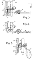
- Figs. 1 to 5 show a first embodiment of the system consisting of a frame and a support for sun lenses, in other words protective filtering lenses, according to the invention.
- the number 1 indicates in a general way the spectacle frame with lenses L1.
- the frame comprises a pair of side bars 3 hinged by hinges 5 to front elements 7 for the connection of the lenses L1.
- the lenses are connected together by an intermediate bridge 9, to which are also fitted pads 11 for supporting the spectacles on the nose.
- the whole frame is made from metal wire, but this is not an essential condition.
- connection elements 7 form, at the sides of the first pair of lenses L1, two eyes 13 (only one of which is visible in Fig. 1) formed from a plurality of adjacent helical turns, giving the appearance of a fully compressed coil spring.
- Each eye 13 is located between an end for fastening to the corresponding lens L1 and the corresponding hinge 5 for the side bar 3.
- the number 15 indicates in a general way a support for a second pair of lenses L2 consisting of sun lenses, in other words protective lenses which are colored or in any case filtering.
- the support 15 comprises a portion of metal wire 17 which runs round the top of each lens L2 and is terminated at its ends in pins 19 designed to be inserted into the eyes 13 formed by the connection elements 7 of the frame 1, as shown in particular in Figs. 1 to 4.
- the wire 17 is housed in edge grooves formed on the sun lenses L2.
- It also forms an intermediate bridge 21 having a hook 23 which engages with the intermediate bridge 9 of the frame 1, as shown in particular in Fig. 5.
- the hook 23 could also be formed on the bridge 9 of the frame 1, but this would adversely affect the attractive appearance of the frame, which may be used frequently without the protective lenses L2.
- each lens L2 is mounted not only by means of the portion of wire 17, but also by means of two lower thinner threads, made for example from nylon®, indicated by 25 and forming the lower portion of the rim of each sun lens L2.
- the number 27 indicates connecting elements for fixing each nylon thread 25 to the metal wire 17 above it.
- the support 15 is removed and the appearance of the spectacles is substantially identical to that of conventional spectacles, with the sole exception of the presence of the lateral eyes 13 forming part of the lateral retaining members of the support 15 of the sun lenses L2. These eyes 13 are of very limited size and do not adversely affect the appearance of the frame.
- one of the pins 19 is inserted into the corresponding eye 13.
- the insertion takes place from the top downward.
- the support is then inclined to make the hook 23 formed by the intermediate bridge 21 engage from below with the intermediate bridge 9 of the frame 1.
- the one of the two pins 19 which has not yet been inserted into the corresponding eye 13 is located above its eye and is inserted into it.
- the support 15 with the sun lenses L2 is made to be coupled in a stable way to the frame 1 by means of the two lateral retaining members consisting of the eyes 13 and the pins 19, and by means of the hook 23 formed by the intermediate bridge 21 which engages with the intermediate bridge 9 of the frame.
- the sun lenses L2 are thus kept at a suitable distance from the sight lenses L1, preventing any contact between them and consequently preventing a migration of coloring substance from the lenses L2 to the lenses L1.
- all the mounting operations take place without any contact between the support 15, with the corresponding lenses L2, and the sight lenses L1, so that the latter are not damaged in any way.
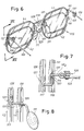
- Figs. 6 to 8 show a second embodiment of the frame and support system according to the invention.
- the frame indicated in a general way by 101, has side bars 103 hinged at 105 to a front portion of the frame, in which sight lenses L1 are inserted.
- the front portion of the frame which retains the lenses L1 comprises an upper metal wire 131 which forms rim means around the lenses and which also forms an intermediate bridge 109.
- the lenses are rimmed below by corresponding wires 133, for example metal wires, whose diameter is preferably smaller than that of the wire 131.
- the wires 133 engage with the wire 131 by means of hooks 135 with the interposition of an elastic element formed by a coil spring 137 which may be formed from the same wire 133 or which may be a mechanically separate element interposed between the wire 133 and the wire 131.
- Each hook 135 engages with an extension 131A of the wire 131 which also forms part of the hinge 105 for hinging the corresponding side bar 103.
- the number 115 indicates in a general way the support of protective sun lenses L2.
- the support 115 is formed by a metal wire 117 which forms a lower portion of the rim of the sun lenses L2 and an intermediate bridge 121 forming a hook 123 for engagement with the bridge 109 of the frame 101.
- the upper part of each rim of the lenses L2 is formed by a thread of smaller diameter, made for example from nylon®, indicated by the number 125 and engaged with the wire 117 by means of hooks 127.
- the pads 111 for support on the nose are carried by a bridge-shaped element 112 soldered to the bridge 109 and having a central bend which forms, together with the bridge 109, a socket 114 into which is inserted the hook 103 formed by the bridge 121 of the support 115 of the sun lenses L2.
- the lateral pins 119 formed by the metal wire 117 are inserted axially into the eyes formed by the turns of the coil springs 137.
- the mounting is carried out in a similar way to that described for the embodiment in Figs. 1 to 5, with the difference that the pins 119 are inserted from the bottom upward, while the hook 123 is engaged from the top downward on the bridge 109.
Landscapes
- Physics & Mathematics (AREA)
- Health & Medical Sciences (AREA)
- General Physics & Mathematics (AREA)
- Ophthalmology & Optometry (AREA)
- Optics & Photonics (AREA)
- Laminated Bodies (AREA)
- Eyeglasses (AREA)
Applications Claiming Priority (2)
| Application Number | Priority Date | Filing Date | Title |
|---|---|---|---|
| IT98FI000088A ITFI980088A1 (it) | 1998-04-15 | 1998-04-15 | Complesso costituito da una montatura per occhiali e un supporto per lenti protettive da sole |
| ITFI980088 | 1998-04-15 |
Publications (1)
| Publication Number | Publication Date |
|---|---|
| EP0950916A1 true EP0950916A1 (fr) | 1999-10-20 |
Family
ID=11352499
Family Applications (1)
| Application Number | Title | Priority Date | Filing Date |
|---|---|---|---|
| EP99830202A Withdrawn EP0950916A1 (fr) | 1998-04-15 | 1999-04-08 | Système constitué par une monture de lunettes et un support pour des lentilles solaires protectives |
Country Status (2)
| Country | Link |
|---|---|
| EP (1) | EP0950916A1 (fr) |
| IT (1) | ITFI980088A1 (fr) |
Citations (4)
| Publication number | Priority date | Publication date | Assignee | Title |
|---|---|---|---|---|
| FR1020344A (fr) * | 1950-05-12 | 1953-02-04 | Lunettes | |
| EP0721134A2 (fr) * | 1994-07-11 | 1996-07-10 | Bottega D'arte In Firenze S.R.L. | Monture de lunettes avec charnière améliorée pour les branches |
| WO1996033440A1 (fr) * | 1995-04-21 | 1996-10-24 | Lindberg Optic Design A/S | Clip de protection pour lunettes |
| WO1997043683A1 (fr) * | 1996-05-16 | 1997-11-20 | Bottega D'arte In Firenze S.R.L. | Monture metallique pour lunettes |
-
1998
- 1998-04-15 IT IT98FI000088A patent/ITFI980088A1/it unknown
-
1999
- 1999-04-08 EP EP99830202A patent/EP0950916A1/fr not_active Withdrawn
Patent Citations (4)
| Publication number | Priority date | Publication date | Assignee | Title |
|---|---|---|---|---|
| FR1020344A (fr) * | 1950-05-12 | 1953-02-04 | Lunettes | |
| EP0721134A2 (fr) * | 1994-07-11 | 1996-07-10 | Bottega D'arte In Firenze S.R.L. | Monture de lunettes avec charnière améliorée pour les branches |
| WO1996033440A1 (fr) * | 1995-04-21 | 1996-10-24 | Lindberg Optic Design A/S | Clip de protection pour lunettes |
| WO1997043683A1 (fr) * | 1996-05-16 | 1997-11-20 | Bottega D'arte In Firenze S.R.L. | Monture metallique pour lunettes |
Also Published As
| Publication number | Publication date |
|---|---|
| ITFI980088A0 (it) | 1998-04-15 |
| ITFI980088A1 (it) | 1999-10-15 |
Similar Documents
| Publication | Publication Date | Title |
|---|---|---|
| JP4699611B2 (ja) | 補助アイウェアを取り付ける方法および装置 | |
| US4834523A (en) | Eyeglasses with separable rims | |
| US5585870A (en) | Rimless spectacles with its lenses supported and clipped at three points | |
| US6659605B2 (en) | Clip-on eyewear | |
| JPH0774864B2 (ja) | 眼 鏡 | |
| US6264326B1 (en) | Wire-and-thread rimmed frame for eyeglasses | |
| US4973148A (en) | Optical accessory for use with spectacles | |
| US5135296A (en) | Eyeglasses having single wire frames | |
| US6113235A (en) | Eyeglasses frame having elastically deformable rim-to-temple joints | |
| US6015212A (en) | Eyeglass frame made of wire with an elastic element | |
| EP0546589A1 (fr) | Support pour verre de lunettes, de préférence sans monture | |
| JPS60146218A (ja) | 眼鏡フレームおよびこれに取り付ける眼鏡フロント用支持構造体 | |
| US6848784B1 (en) | Eyeglass device having primary and auxiliary spectacle frames | |
| US5650836A (en) | Hanger with temple support for display of eyeglasses | |
| EP0950916A1 (fr) | Système constitué par une monture de lunettes et un support pour des lentilles solaires protectives | |
| AU2001270731B2 (en) | Spectacles with wire-like branches | |
| US9500879B2 (en) | Eyewear | |
| KR100350653B1 (ko) | 브릿지로 장착되는 클립온형 선글라스 | |
| CN110618539A (zh) | 具有侧向插入元件的眼镜框架 | |
| KR101941402B1 (ko) | 안경테와 안경다리의 연결구조체 | |
| US6464352B1 (en) | Detachable shelter frame for mounting in front of a primary spectacle frame | |
| WO2012044142A1 (fr) | Lunettes | |
| CN100526938C (zh) | 夹持镜片型眼镜 | |
| JP3065979U (ja) | メガネ | |
| CN212364740U (zh) | 一种无框眼镜的连接结构 |
Legal Events
| Date | Code | Title | Description |
|---|---|---|---|
| PUAI | Public reference made under article 153(3) epc to a published international application that has entered the european phase |
Free format text: ORIGINAL CODE: 0009012 |
|
| AK | Designated contracting states |
Kind code of ref document: A1 Designated state(s): AT BE CH CY DE DK ES FI FR GB GR IE IT LI LU MC NL PT SE |
|
| AX | Request for extension of the european patent |
Free format text: AL;LT;LV;MK;RO;SI |
|
| AKX | Designation fees paid | ||
| REG | Reference to a national code |
Ref country code: DE Ref legal event code: 8566 |
|
| STAA | Information on the status of an ep patent application or granted ep patent |
Free format text: STATUS: THE APPLICATION IS DEEMED TO BE WITHDRAWN |
|
| 18D | Application deemed to be withdrawn |
Effective date: 20000421 |