EP0950944A2 - Anzeigesteuerungsvorrichtung und Anzeigesystem - Google Patents
Anzeigesteuerungsvorrichtung und Anzeigesystem Download PDFInfo
- Publication number
- EP0950944A2 EP0950944A2 EP99107656A EP99107656A EP0950944A2 EP 0950944 A2 EP0950944 A2 EP 0950944A2 EP 99107656 A EP99107656 A EP 99107656A EP 99107656 A EP99107656 A EP 99107656A EP 0950944 A2 EP0950944 A2 EP 0950944A2
- Authority
- EP
- European Patent Office
- Prior art keywords
- display
- image
- piece
- image information
- control apparatus
- Prior art date
- Legal status (The legal status is an assumption and is not a legal conclusion. Google has not performed a legal analysis and makes no representation as to the accuracy of the status listed.)
- Granted
Links
Images








Classifications
-
- G—PHYSICS
- G06—COMPUTING OR CALCULATING; COUNTING
- G06F—ELECTRIC DIGITAL DATA PROCESSING
- G06F3/00—Input arrangements for transferring data to be processed into a form capable of being handled by the computer; Output arrangements for transferring data from processing unit to output unit, e.g. interface arrangements
- G06F3/01—Input arrangements or combined input and output arrangements for interaction between user and computer
- G06F3/03—Arrangements for converting the position or the displacement of a member into a coded form
- G06F3/033—Pointing devices displaced or positioned by the user, e.g. mice, trackballs, pens or joysticks; Accessories therefor
- G06F3/038—Control and interface arrangements therefor, e.g. drivers or device-embedded control circuitry
-
- G—PHYSICS
- G06—COMPUTING OR CALCULATING; COUNTING
- G06F—ELECTRIC DIGITAL DATA PROCESSING
- G06F3/00—Input arrangements for transferring data to be processed into a form capable of being handled by the computer; Output arrangements for transferring data from processing unit to output unit, e.g. interface arrangements
- G06F3/01—Input arrangements or combined input and output arrangements for interaction between user and computer
- G06F3/048—Interaction techniques based on graphical user interfaces [GUI]
- G06F3/0484—Interaction techniques based on graphical user interfaces [GUI] for the control of specific functions or operations, e.g. selecting or manipulating an object, an image or a displayed text element, setting a parameter value or selecting a range
- G06F3/04845—Interaction techniques based on graphical user interfaces [GUI] for the control of specific functions or operations, e.g. selecting or manipulating an object, an image or a displayed text element, setting a parameter value or selecting a range for image manipulation, e.g. dragging, rotation, expansion or change of colour
-
- G—PHYSICS
- G06—COMPUTING OR CALCULATING; COUNTING
- G06F—ELECTRIC DIGITAL DATA PROCESSING
- G06F3/00—Input arrangements for transferring data to be processed into a form capable of being handled by the computer; Output arrangements for transferring data from processing unit to output unit, e.g. interface arrangements
- G06F3/14—Digital output to display device ; Cooperation and interconnection of the display device with other functional units
-
- G—PHYSICS
- G09—EDUCATION; CRYPTOGRAPHY; DISPLAY; ADVERTISING; SEALS
- G09G—ARRANGEMENTS OR CIRCUITS FOR CONTROL OF INDICATING DEVICES USING STATIC MEANS TO PRESENT VARIABLE INFORMATION
- G09G5/00—Control arrangements or circuits for visual indicators common to cathode-ray tube indicators and other visual indicators
-
- G—PHYSICS
- G09—EDUCATION; CRYPTOGRAPHY; DISPLAY; ADVERTISING; SEALS
- G09G—ARRANGEMENTS OR CIRCUITS FOR CONTROL OF INDICATING DEVICES USING STATIC MEANS TO PRESENT VARIABLE INFORMATION
- G09G5/00—Control arrangements or circuits for visual indicators common to cathode-ray tube indicators and other visual indicators
- G09G5/36—Control arrangements or circuits for visual indicators common to cathode-ray tube indicators and other visual indicators characterised by the display of a graphic pattern, e.g. using an all-points-addressable [APA] memory
-
- H—ELECTRICITY
- H04—ELECTRIC COMMUNICATION TECHNIQUE
- H04N—PICTORIAL COMMUNICATION, e.g. TELEVISION
- H04N5/00—Details of television systems
- H04N5/76—Television signal recording
- H04N5/765—Interface circuits between an apparatus for recording and another apparatus
- H04N5/775—Interface circuits between an apparatus for recording and another apparatus between a recording apparatus and a television receiver
-
- G—PHYSICS
- G06—COMPUTING OR CALCULATING; COUNTING
- G06F—ELECTRIC DIGITAL DATA PROCESSING
- G06F2203/00—Indexing scheme relating to G06F3/00 - G06F3/048
- G06F2203/038—Indexing scheme relating to G06F3/038
- G06F2203/0383—Remote input, i.e. interface arrangements in which the signals generated by a pointing device are transmitted to a PC at a remote location, e.g. to a PC in a LAN
-
- G—PHYSICS
- G09—EDUCATION; CRYPTOGRAPHY; DISPLAY; ADVERTISING; SEALS
- G09G—ARRANGEMENTS OR CIRCUITS FOR CONTROL OF INDICATING DEVICES USING STATIC MEANS TO PRESENT VARIABLE INFORMATION
- G09G2340/00—Aspects of display data processing
- G09G2340/04—Changes in size, position or resolution of an image
- G09G2340/0407—Resolution change, inclusive of the use of different resolutions for different screen areas
-
- G—PHYSICS
- G09—EDUCATION; CRYPTOGRAPHY; DISPLAY; ADVERTISING; SEALS
- G09G—ARRANGEMENTS OR CIRCUITS FOR CONTROL OF INDICATING DEVICES USING STATIC MEANS TO PRESENT VARIABLE INFORMATION
- G09G2340/00—Aspects of display data processing
- G09G2340/12—Overlay of images, i.e. displayed pixel being the result of switching between the corresponding input pixels
-
- G—PHYSICS
- G09—EDUCATION; CRYPTOGRAPHY; DISPLAY; ADVERTISING; SEALS
- G09G—ARRANGEMENTS OR CIRCUITS FOR CONTROL OF INDICATING DEVICES USING STATIC MEANS TO PRESENT VARIABLE INFORMATION
- G09G2370/00—Aspects of data communication
- G09G2370/04—Exchange of auxiliary data, i.e. other than image data, between monitor and graphics controller
- G09G2370/045—Exchange of auxiliary data, i.e. other than image data, between monitor and graphics controller using multiple communication channels, e.g. parallel and serial
-
- G—PHYSICS
- G09—EDUCATION; CRYPTOGRAPHY; DISPLAY; ADVERTISING; SEALS
- G09G—ARRANGEMENTS OR CIRCUITS FOR CONTROL OF INDICATING DEVICES USING STATIC MEANS TO PRESENT VARIABLE INFORMATION
- G09G5/00—Control arrangements or circuits for visual indicators common to cathode-ray tube indicators and other visual indicators
- G09G5/003—Details of a display terminal, the details relating to the control arrangement of the display terminal and to the interfaces thereto
- G09G5/006—Details of the interface to the display terminal
-
- G—PHYSICS
- G09—EDUCATION; CRYPTOGRAPHY; DISPLAY; ADVERTISING; SEALS
- G09G—ARRANGEMENTS OR CIRCUITS FOR CONTROL OF INDICATING DEVICES USING STATIC MEANS TO PRESENT VARIABLE INFORMATION
- G09G5/00—Control arrangements or circuits for visual indicators common to cathode-ray tube indicators and other visual indicators
- G09G5/08—Cursor circuits
-
- G—PHYSICS
- G09—EDUCATION; CRYPTOGRAPHY; DISPLAY; ADVERTISING; SEALS
- G09G—ARRANGEMENTS OR CIRCUITS FOR CONTROL OF INDICATING DEVICES USING STATIC MEANS TO PRESENT VARIABLE INFORMATION
- G09G5/00—Control arrangements or circuits for visual indicators common to cathode-ray tube indicators and other visual indicators
- G09G5/36—Control arrangements or circuits for visual indicators common to cathode-ray tube indicators and other visual indicators characterised by the display of a graphic pattern, e.g. using an all-points-addressable [APA] memory
- G09G5/39—Control of the bit-mapped memory
- G09G5/393—Arrangements for updating the contents of the bit-mapped memory
-
- H—ELECTRICITY
- H04—ELECTRIC COMMUNICATION TECHNIQUE
- H04N—PICTORIAL COMMUNICATION, e.g. TELEVISION
- H04N21/00—Selective content distribution, e.g. interactive television or video on demand [VOD]
- H04N21/40—Client devices specifically adapted for the reception of or interaction with content, e.g. set-top-box [STB]; Operations thereof
- H04N21/43—Processing of content or additional data, e.g. demultiplexing additional data from a digital video stream; Elementary client operations, e.g. monitoring of home network or synchronising decoder's clock; Client middleware
- H04N21/431—Generation of visual interfaces for content selection or interaction; Content or additional data rendering
- H04N21/4312—Generation of visual interfaces for content selection or interaction; Content or additional data rendering involving specific graphical features, e.g. screen layout, special fonts or colors, blinking icons, highlights or animations
- H04N21/4316—Generation of visual interfaces for content selection or interaction; Content or additional data rendering involving specific graphical features, e.g. screen layout, special fonts or colors, blinking icons, highlights or animations for displaying supplemental content in a region of the screen, e.g. an advertisement in a separate window
-
- H—ELECTRICITY
- H04—ELECTRIC COMMUNICATION TECHNIQUE
- H04N—PICTORIAL COMMUNICATION, e.g. TELEVISION
- H04N5/00—Details of television systems
- H04N5/44—Receiver circuitry for the reception of television signals according to analogue transmission standards
- H04N5/445—Receiver circuitry for the reception of television signals according to analogue transmission standards for displaying additional information
- H04N5/45—Picture in picture, e.g. displaying simultaneously another television channel in a region of the screen
Definitions
- the present invention relates to a display control apparatus and a display system, and more particularly to a display control apparatus for controlling the multiwindow display of data input from a plurality of personal computers and to a display system using such display control apparatus.
- a conventional large display device is connected to PC in one-to-one correspondence. Therefore, if a plurality of persons give a presentation, it is necessary to change the connection of PC to the display device or copy a file such as presentation materials to another PC each time a different person gives a presentation.
- the work of a connection change is cumbersome and if a file is to be copied to a different PC, many inconveniences occur such as inability of immediately displaying data because of different applications and versions or the like. In such cases, an advance of the meeting is often interrupted.
- an image display system is desired to have a function of displaying image information supplied from a plurality of PC's (image sources) in a switched manner or at the same time while a meeting advances, a function of displaying the minutes of proceedings written by another PC for the confirmation by all participants.
- the present invention has been made to solve the above-described problems associated with conventional techniques and provide a display system capable of controlling a display of images input from a plurality of image sources by using a common input/output device.
- a display system for receiving image data from a plurality of image sources and displaying the received image data on a display unit, comprises: input means for inputting a control signal supplied from an input/output unit; control means for controlling an image to be displayed on the display unit in accordance with the control signal input from the input means; image selection means for selecting a desired image from images displayed on the display unit; and switching means for switching an image to be controlled by the control means in accordance with the image selected by the image selection means.
- Another display system of the invention for receiving image data from a plurality of image sources and displaying the received image data on a display unit, comprises: scale varying means for varying a display scale of each image to be displayed on the display unit; a memory structured hierarchically for storing each image to be displayed on the display unit at each hierarchical level assigned with a priority order; and display style setting means for setting a display style of each image to be displayed on the display unit, in accordance with a scaling factor of the image set by the scale varying means and the priority order of the image stored in the memory.
- a display control apparatus having user information input means and connected via communications means to at least one image display apparatus for outputting image information, comprises: image input means for receiving at least one piece of image information output from at least one image display apparatus; a display device for displaying at least one piece of received image information; first overlay display means for displaying in an overlay manner a first position indication mark on the display device in order to select one piece of image information from at least one piece of image information displayed on the display device; second overlay display means for displaying in an overlay manner a second position indication mark on the display device; and control means for determining a display position of the second position indication mark to be displayed by the second overlay display means in accordance with the user information supplied via the communications means from the user information input means, relative to the one piece of the image information selected by the first position indication mark displayed by the first overlay display means, and controlling an operation of the second overlay display means in accordance with the determined display position.
- Fig. 1 is a block diagram showing the structure of a display system according to a first embodiment of the invention.
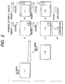
- Fig. 2 is a diagram showing examples of a display layout of a display device when a plurality of image sources are input.
- Fig. 3 is a diagram showing the structure of a selection portion.
- Figs. 4A, 4B and 4C are diagrams showing examples of images and a display pointer on a display device.
- Fig. 5 is a block diagram showing the structure of a display system according to a second embodiment of the invention.
- Fig. 6 is a block diagram showing the structure of a display system according to a third embodiment of the invention.
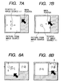
- Figs. 7A and 7B show a display screen, a window, a main pointer, and an image source pointer on a display control system
- Fig. 7A illustrates a control by the image source pointer
- Fig. 7B illustrates a control by the main pointer.
- Figs. 8A and 8B show a display screen, windows, a main pointer, and an image source pointer on a display control system
- Fig. 8A illustrates a selection of a window of an image source 1-1 with the main pointer
- Fig. 8B illustrates a selection of a window of an image source 1-2 with the main pointer.
- Fig. 9 is a diagram illustrating a relation between a general software configuration and an embodiment software configuration under the graphic user interface (GUI) environment on the image source side.
- GUI graphic user interface
- Fig. 10 is a diagram showing an operation screen of an application running under the GUI environment on the image source side according to an embodiment.
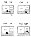
- Figs. 11A and 11B show the display screen of a display control system
- Fig. 11A illustrates a selection of a window of an image source 1-1 with a main pointer
- Fig. 11B illustrates a selection of a clip board icon Y1 with a main pointer.
- Figs. 12A and 12B show the display screen of a display control system
- Fig. 12A illustrates a selection of a window of an image source 1-1 with a main pointer
- Fig. 12B illustrates a selection of a window of an image source 1-2 with the main pointer.
- Fig. 13 is a flow chart illustrating the operation of a main process to be executed when data is input from an infrared data control portion of a control portion 6 of a display control system 40.
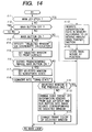
- Fig. 14 is a flow chart illustrating a process R1 in the flow chart shown in Fig. 13.
- Fig. 15 is a flow chart illustrating a process R2 in the flow chart shown in Fig. 13.
- Fig. 16 is a flow chart illustrating a process R3 in the flow chart shown in Fig. 13.
- Fig. 17 is a flow chart illustrating a process R4 in the flow chart shown in Fig. 13.
- Fig. 18 is a flow chart illustrating a process R5 in the flow chart shown in Fig. 13.
- Fig. 19 is a flow chart illustrating the operation of a main process to be executed when data is input from a packet control portion of the control portion 6 of the display control system 40.
- Fig. 20 is a flow chart illustrating a process P1 in the flow chart shown in Fig. 19.
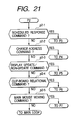
- Fig. 21 is a flow chart illustrating a process P2 in the flow chart shown in Fig. 19.
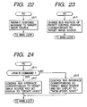
- Fig. 22 is a flow chart illustrating a process P3 in the flow chart shown in Fig. 19.
- Fig. 23 is a flow chart illustrating a process P4 in the flow chart shown in Fig. 19.
- Fig. 24 is a flow chart illustrating a process P5 in the flow chart shown in Fig. 19.
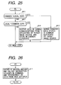
- Fig. 25 is a flow chart illustrating a process P6 in the flow chart shown in Fig. 19.
- Fig. 26 is a flow chart illustrating a process P7 in the flow chart shown in Fig. 19.
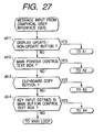
- Fig. 27 is a flow chart illustrating the operation of a process to be executed when a message is input from GUI of the control portion 6 of the display control system 40.
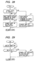
- Fig. 28 is a flow chart illustrating a process A1 in the flow chart shown in Fig. 27.
- Fig. 29 is a flow chart illustrating a process A2 in the flow chart shown in Fig. 27.
- Fig. 30 is a flow chart illustrating a process A3 in the flow chart shown in Fig. 27.
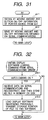
- Fig. 31 is a flow chart illustrating a process A4 in the flow chart shown in Fig. 27.
- Fig. 32 is a flow chart illustrating the operation of a process to be executed when a display software loading command is obtained from a serial communications driver of the control portion 6 of the display control system 40.
- Fig. 1 is a block diagram showing the structure of a display system according to the first embodiment of the invention.
- Fig. 1 Each block shown in Fig. 1 will be described.
- information supplied from four independent image sources (such as note PC) is displayed on one monitor and an input/output device of each image source, such as a mouse, a keyboard, a remote controller and a speaker, is controlled in cooperation with image data displayed on the monitor.
- the number of image sources may be larger than or smaller than four.
- Reference numeral 31 represents a display system.
- Reference numerals 1-1, 1-2, 1-3 and 1-4 represent sources of image signals (hereinafter called “image source 1") which may be a personal computer, a work station, a digital television, or a camcorder (video camera). In this embodiment, four- image sources are used.
- Reference numerals 2-1, 2-2, 2-3 and 2-4 represent an input portion for receiving image data output from each image source 1 (hereinafter called “input portion 2").
- Each input portion 2 has: an A/D converter and a PLL (phase locked loop) circuit for sampling image data if the input portion receives analog image data; a decoder and a differential buffer if the input portio receives digital image data such as LVDS (low voltage differential signalling); or an encoder for encoding a composite signal into R, G and B signals if the input portion receives television or camcorder composite signals.
- Each input portion 2 receives from the image source 1 not only the image data but also control signals to be used for reception of image data, such as a horizontal sync signal for line synchronization, a vertical sync signal for frame or field synchronization, a clock signal for sampling each pixel, and a display enable signal indicating a transfer period of effective image data.
- Each input portion 2 receives image data at an independent timing from other input portions.
- the input portion 2 has serial communications means to be described later for communications with the image source 1.
- Reference numerals 3-1, 3-2, 3-3 and 3-4 represent a display format conversion portion (hereinafter called a "display format conversion portion 3") for converting a display format (the numbers of display lines, dots and colors) of image data received at the input portion 2, under the control of a control portion 6.
- Reference numerals 4-1, 4-2, 4-3 and 4-4 represent bus interface portions for inputting independent four image data sets to one common bus.
- Reference numeral 5 represents a bus controller for receiving image data output from each bus interface portion 4 and image data output from a frame memory controller 7 and a superposition data controller 8 and for arbitrating transfer of the image data in accordance with a priority order upon reception of a transfer request from these controllers.
- Reference numeral 6 represents a control portion for controlling the entirety of the display system.
- the control portion 6 has a CPU with a computing ability, a RAM for temporarily storing data, a ROM for storing control programs, a counter for counting time, a peripheral input/output interface, and the like respectively not shown.
- the control portion 6 may be structured by using only logic circuits.
- the control programs may be stored in ROM or may be transferred externally via a peripheral input/output interface.
- the frame memory controller 7 converts and controls the image data input through arbitration by the bus controller 5 so as to obtain image data suitable for a frame memory 9.
- the frame memory controller 7 may be a CPU or a media processor capable of parallel computing.
- the frame memory 9 stores image data of at least one frame to be displayed on a display device 13.
- the frame memory 9 has a plurality of hierarchical levels.
- the superposition data controller 8 controls to superpose image data different from that supplied from each input portion 2 on the display device 13.
- Reference numeral 10 represents a superposition data memory for storing data to be superposed.
- Reference numeral 11 represents an output display format conversion portion for receiving image data on the bus under the control of the bus controller 5 and for converting it into image data having a display format suitable for a display driving controller 12 which drives the display device 13.
- the display device 13 may be a CRT or a flat display panel (liquid crystal, plasma or the like) having a matrix electrode structure.
- the display device 13 may be a single display device or a plurality of display devices. Image data supplied from the image source 1 is displayed on this display device 13.
- Reference numeral 14 represents a selection portion for switching between high speed serial data lines which can transmit and receive multiplexed packet data of an input/output device of each image source 1 such as a mouse (infrared input type), a keyboard and a speaker.
- An example of transmitting multiplexed packet data of received data is IEEE 1394 (The Institute of Electrical and Electronics Engineers, Inc), USB (Universal Serial Bus) or the like.
- Reference numeral 15 represents a packet distribution control portion for controlling to distribute serial data selected by the selection portion 14 in the unit of packet.
- Reference numeral 16 represents a packet control portion with a FIFO memory for controlling the reception timing of packet data supplied to the display system.
- Reference numeral 21 represents a display pointer controller for controlling to move the cursor of a mouse and an image superposed on the display device.
- a plurality of display pointer controllers may be provided.
- Reference numeral 22 represents a joy stick for moving the mouse of the image source 1
- reference numeral 24 represents a joy stick for moving a display pointer.
- Reference numeral 23 represents a control button of the mouse
- reference numeral 25 represents a control button of the display pointer, these buttons serving as confirmation buttons.
- Reference numeral 30 represents a change button for changing a display layout on the display device.
- Reference numeral 20 represents an infrared data receiving portion for receiving infrared data transmitted from the display pointer controller 21.
- Reference numeral 19 represents an infrared data control portion for outputting data received from the receiving portion 20 to the control portion 6 and an infrared data conversion portion 18 which converts the data supplied from the infrared data control portion 19 into a serial data packet.
- Reference numeral 17 represents a FIFO memory which is used for controlling the timing of transferring the packet data supplied from the infrared data conversion portion 18 to the packet control distribution control portion 15.
- Reference numeral 26 represents a packet control portion with a FIFO memory which is used for controlling the reception timing of a sound packet supplied from each image source 1.
- Reference numeral 27 represents a D/A converter for converting input digital sound data into analog data.
- Reference numeral 28 represents a sound amplifier, and reference numeral 29 represents a speaker of the display system 31.
- Each image source 1 and display system 31 communicate with each other via a bi-directional serial communications line of the input portion 2 after powers are turned on.
- Each input portion 2 supplies the image source 1 with data such as the numbers of dots, display lines, display colors, and a video output timing.
- the communications are performed by using a communications protocol predetermined both by the input portion 2 and image source 1.
- a DDC Display Data Channel 1 of VESA (Video Electronics Standards Association) in USA may be used, and EDID (Extended Display Identification Data) of VESA may be used as the data format.
- VESA Video Electronics Standards Association
- EDID Extended Display Identification Data
- the numbers of display dots, display lines and display colors of the display device 13 are supplied, or the display format predetermined at the control portion 6 may be supplied.
- each image source 1 outputs image data and its control signals to the input portion 2.
- the input portion 2 always monitors a connection identification signal to be supplied from the image source in order to check the number of image sources 1 connected to the display system 31.
- the input portion 2 receives the connection identification signal from the image source as a logical binary signal "1" or "0".
- connection cable If the connection cable is cut or the power of the image source is turned off, the logical signal "0" is supplied because the input portion 2 is terminated with a resistor.
- the display system 31 can therefore recognize that image data is not input. This monitor information is supplied to the control portion 6 at a predetermined interval.
- the control portion 6 first detects the connection identification signal of the input portion 2-1. If the connection identification signal is "1”, the input portion 2-1 sends the received image data to the display format conversion portion 3-1 to covert the format of the image data, whereas if the connection identification signal is "0", the control portion 6 checks the connection identification signal of the next input portion 2-2 and scans the input portion 2 until the connection identification signal of "1" is detected. If all the connection identification signals are "0", the display system 31 enters a power save mode to lower a power supply to the constituent elements excepting the control portion 6, selection portion 14, packet distribution control portion 15, packet control portion 16 with FIFO, FIFO memory 17, infrared data conversion portion 18, infrared data control portion 19, and infrared data receiving portion 20.
- Display data in ROM of the control portion 6 is stored in the superposition data memory 10 via the bus and data controller 8.
- the display data may be supplied to the control portion 6 via the selection portion 14 and packet control portion 16 with FIFO to be described later.
- connection identification signal of only the input portion 2-1 is "1" and the signals of the other input portions are "0", will be described.
- the input portion 2-1 outputs image signals having a desired format to the display format conversion portion 3-1. If the supplied display format is equal to the display format (dot number, line number and color number) of the display device 13, the supplied image data is passed to the bus interface, whereas if they are different, the supplied display format is converted into the display format of the display device 13 by processing the supplied image data to have proper dot number and line number. If the number of colors of the supplied image data is larger than the number of colors the display device 13 can display, the number of bits of image data is reduced at an intermediate image data process such as a dither process.
- the image data output from the display format conversion portion 3-1 is stored in the frame memory 9 via the bus interface 4-1, bus controller 5 and frame memory controller 7.
- the frame memory 9 has a plurality of hierarchical levels.
- the level at which the input data is stored is controlled by the bus controller 5 under the control of the control portion 6.
- Image data stored in the frame memory 9 is output to the bus at a timing controlled by the control portion 6 and to the output display format conversion portion 11.
- the hierarchical level of image data to be output is determined by the bus controller 5 under the control of the control portion 6.
- display data stored in the superposition data memory 10 is output to the bus via the superposition data controller 8 under the control of the control portion 6 to be displayed on the display device 13.
- Either the superposition data or the input image data output to the bus via the frame memory controller 7 is selected by the output display format conversion portion 11 and the selected data is supplied to the display driving controller 12. This selection timing is determined by the control portion 6.
- the output display format conversion portion 11 converts the selected image data into data having a data bus width and the like suitable for the display driving controller 12.
- the image data converted by the conversion portion 11 is output to the display driving controller 12 which generates a drive signal for driving the display device 13.
- this drive signal includes a line sync signal, a frame sync signal, an image data shift clock, image data, an alternating current signal and the like for driving a drive IC of the display device 13.
- the display driving controller 12 converts the digital image data into analog R, G, and B image data and outputs them to the display device 13 together with the horizontal and vertical sync signals.
- the display controller 12 supplies proper image data to the display device 13 to display the image data thereon.
- the display pointer controller 21 forms a packet of X and Y information of the joy stick 22 and ON/OFF information of the control button 23 at a predetermined interval and converts the packet into an infrared signal which is then transmitted.
- the X and Y information of the joy stick 22 may be either absolute coordinate values or relative coordinate values, this being applicable also to the X and Y information of the other joy stick 23.
- the transmitted infrared signal is received by the infrared data receiving portion 20 which converts it into an electric signal.
- the infrared data control portion 19 derives necessary X and Y coordinate values and button ON/OFF data from the packeted electric signal supplied from the receiving portion 20, and outputs the derived data to the infrared data conversion portion 18.
- the infrared data conversion portion 18 converts again the supplied X and Y information into serial packet data receivable by the image source 1-1. This conversion may be performed in accordance with the specifications of USB (Universal Serial Bus) in recent practical use.
- This packet data is input via the data transfer timing control FIFO memory 17 to the packet distribution control portion 15 and combined (mixed) with the input/output data packet of the image source 1-1.
- the combined (mixed) X and Y information is transferred via the selection portion 14 to the image source 1-1 so that the position information of the mouse is supplied to a CPU of the image source 1-1.
- the selection portion 14 selects a serial data line of the image source 1-1 whose image is currently displayed, under the control of the control portion 6 which recognizes a connection of the image source 1-1.
- the display pointer controller 21 forms a packet of X and Y information of the joy stick 24 at a predetermined interval and converts the packet into an infrared signal which is then transmitted.
- the data receiving portion 20 converts the received infrared data into an electric signal.
- the infrared data control portion 19 derives necessary X and Y information from the packeted electric signal, and outputs the derived data to the bus controller 5. In this case, if the X and Y information is relative coordinate values, it is converted into the absolute coordinate values which are supplied to the bus controller 8. Conversion into the absolute coordinate values is also applied in the following description.
- the bus controller 5 controls an output timing when the data stored in the superposition data memory 10 is output to the output display format conversion portion 11 to display the superposition data at the X and Y coordinate values.
- the display of the superposition data is not performed depending upon an instruction from the control portion 6.
- the input portion 2-1 detects the connection identification signal and supplies the control portion with the connection identification signal information.
- the control portion 6 supplies the conversion parameters to the display format conversion portions 3-1 and 3-2 for the display format conversion of the image data- of the image sources 1-1 and 1-2.
- the control portion 6 also determines the hierarchical level at which the image data of the image sources 1-1 and 1-2 is stored in the frame memory 9.
- the hierarchical levels of the frame memory 9 have a priority order. If a plurality of hierarchical data are to be output to the same area of the display device, the output format conversion portion 11 is so instructed that image data having a higher priority order of the hierarchical level is more preferentially displayed than image data having a lower priority order.
- Fig. 2 shows examples of a display layout of the display device 13 when a plurality of image sources are connected.
- a first image (1-1) input from the image source 1-1 is displayed on the full screen of the display device
- a second image (1-2) is input from the image source 1-2.
- Each display example can be realized by changing the display scaling at the display format conversion portions 3-1 and 3-2 and by changing the hierarchical level of the frame memory 9 having a priority order of the hierarchical level at which image data is stored.
- the display example (a) shown in Fig. 2 is realized in the following manner.
- the display format conversion portion 3-1 stores the image data of the input portion 2-2 in the frame memory 9 at the hierarchical level of the second priority order without performing scaling.
- the display format control portion 3-2 performs scaling of the image data of the image source 1-2 to reduce the image data by thinning input display dots and lines.
- the reduced image data is stored in the frame memory 9 at the hierarchical level of the first priority order.
- both the display format conversion portions 3-1 and 3-2 perform scaling to display two images without superposing them.
- both the display format conversion portions 3-1 and 3-2 do not perform scaling and the image data is stored in the frame memory 9 at the hierarchical level of the first priority order after each image data of the images (1-1) and (1-2) is processed at least in the unit of one pixel by a calculation circuit of the frame memory controller 7.
- the display layout of the images can be freely changed by using scaling at the display format conversion portions 3 and the hierarchical level of the frame memory 9.
- This display layout change can be performed by instructing the control portion 6 to present one of the display examples (a) to (e) shown in Fig. 2 by pressing the button 30 of the display pointer controller 21 and notifying the control portion 6 of the depression via the receiving portion 20 and infrared data control portion 19. Each time a display layout change is instructed, the control portion 6 notifies a change in the display parameters to the display format conversion portion 3, bus controller 5 and frame memory controller 7.
- the display pointer controller 21 has the joy stick (mouse) 22 as an input device of image sources, the control button 23 functioning as the confirmation button of the joy stick 22, the joy stick 24 for controlling a pointer displayed on the display device -13 and superposed upon the input image data, and the control button 25 functioning as the confirmation button of the joy stick 24.
- the joy stick is used as the input device of the image source 1, an input device such as a keyboard and a tablet may also be used and the output device such as a liquid crystal display and a small printer may also be used.
- the X and Y coordinate values of the joy stick 22 are supplied to the control portion 6 via the receiving portion 20 and infrared data control portion 19.
- the control portion 6 calculates coordinate values of four corner points of a window of the display device in which an input image is currently displayed, by using the numbers of dots and lines used by each display format conversion portion 3, and always stores the calculated coordinate values.
- the X and Y coordinate values sent from the joy stick 24 are sent to the control portion at a predetermined interval.
- the superposition data is output to the output display format conversion portion 11.
- the joy stick 22 which is one of the image source input/output devices is connected to the image source 1-1 via the receiving portion 20, infrared data control portion 19, infrared data conversion portion 18, FIFO memory 17, packet distribution control portion 15 and selection portion 14.
- the pointer figure in the superposition data memory 10 may be changed by each image source via the route of the selection portion 14, packet control portion 16 with FIFO, control portion 6, bus controller 5 and superposition data controller 8, or may be replaced by a pointer figure stored in ROM of the control portion 6 via the route of the bus controller 5 and superposition data controller 8.
- the control portion 6 judges the display window in which the X and Y coordinate values of the display pointer joy stick 24 are located to thereby select the desired image source.
- the control portion 6 supplies a control signal to disconnect once the selection portion 14, and after a predetermined time lapse, the serial data line of the image source 1-2 is connected to the packet distribution control portion 15.
- peripheral devices using a serial data protocol capable of a hot plug-in connection can be reconfigured relative to a host CPU (in this embodiment, image source 1). Therefore, the joy stick 22 can be used as the input/output device (such as mouse) of the image source 1-2.
- a peripheral device using USB Universal Serial Bus
- USB Universal Serial Bus
- a peripheral device using USB is assigned a specific peripheral device address when it is connected to the host CPU, and the electrical characteristics of the peripheral device are supplied to the host CPU.
- the host CPU received the electrical characteristics reconfigures the addresses of connected peripheral devices to realize a hot plug-in connection.
- Fig. 3 is a diagram showing the structure of the selection portion 14.
- serial data lines of the image sources 1-1, 1-2, 1-3 and 1-4 are connected via relays 101, 102, 103 and 104 to the packet distribution control portion 15.
- Switches of the relays 101 to 104 are controlled by transistors 105 to 108.
- a control signal from the control portion 6 is applied to the base of each of the transistors 105 to 108. If the levels of all the control signals are "L”, collector current will not flow through the transistors and the relays 101 to 104 are not operated and become open. Therefore, the image sources 1 and packet distribution control portion 15 are disconnected.
- the image source 1 detects a connection state of a peripheral device at a time interval t. This time interval t is counted by an internal counter of the control portion 6 and the control portion 6 stores the non-connection state information. After a lapse of at least the time t, the control portion 6 applies a control signal "H" to the base of the transistor to turn on the relay, to which the serial data line of the image source (e.g., image source 1-2) to be connected is connected, and to connect only one serial bus line to the packet distribution control portion 15. With these operations, the joy stick 22 of the display pointer controller 21 operates as the input/output device (such as a mouse) of the image source (image source 1-2) corresponding to the connection established serial data line.
- the input/output device such as a mouse
- switching between serial data lines is performed by using relays.
- relays semiconductor switches or mechanical switches may also be used.
- the selection portion 14 has also output paths to the packet control portion 16 with FIFO without intervention of switches such as relays. These output paths can be used to control the control portion 6 directly and independently from each image source 1 by using the serial data lines. Programs to be executed by the control portion 6 may be transferred via these output paths to make the control portion 6 execute the programs. Display data stored in the superposition data memory 10 may also be transferred via these output paths.
- Figs. 4A to 4C are diagrams showing display examples of an image and a display pointer on the display device 13.
- images A, B, C and D of the four image sources corresponding to the image sources 1-1, 1-2, 1-3 and 1-4 are displayed on the display device without any space therebetween.
- the coordinate values of the display position of the display pointer are X and Y in the X- and Y-axis directions and that the four corner coordinate values of the display window A are (a0, a2), (a1, a2), (a1, a3) and (a0, a3) in the clockwise direction and those of the display windows B, C and D are determined in the similar manner.
- the display area of the display pointer can be recognized by using a combination of simple addition and subtraction operations:
- the window under the display pointer corresponds to both the windows A and B.
- the image (in this case, A) having a higher hierarchical level of the frame memory 9 is selected.
- control portion 6 can recognize the image source corresponding to the image under the display pointer in accordance with the X and Y coordinate data of the joy stick 24, the four corner coordinate data of each image data display window, and the priority order data of the frame memory storing the image data.
- the display of images entered from a plurality of image sources 1 on the display device can be controlled easily by using the display controller 21 which is the input/output device common to all the image sources.
- the display of the image data can be changed freely in accordance with the scaling by the display format conversion portion 3 and the hierarchical level of the frame memory 9. Therefore, the display control of images entered from a plurality of image sources, such as a change in the display layout, can be performed easily by using the display controller 21 which is the input/output device common to all the image sources.
- Fig. 5 is a block diagram showing the structure of a display system according to the second embodiment of the invention.
- Television signals received by an antenna 209 are detected and frequency-modulated by television tuners 205 to 208.
- Each encoder 201 to 204 decodes television signals having a standard signal format such as NTSC, PAL and SECAM into composite video signals and sound signals.
- the decoded composite signal is input to each input portion 2 and displayed on the display device in the manner similar to the first embodiment.
- each tuner such as a selection of a broadcast station
- on/off information of the button of the display pointer controller 21 is supplied to the selection portion via the serial control signal line and via the route of the receiving portion 20, infrared data control portion 19, infrared data conversion portion 18, FIFO memory 17 and packet distribution control portion 15.
- the control portion 6 controls the selection portion 14 to select one of the tuners 205 to 208 by the joy stick 24 which tuner receives television data of a display image. In this manner, the television program of the display image received by the tuner and selected by the joy stick 24 can be changed easily.
- sound data is reproduced from the speaker 29 via the packet distribution control portion 15, packet control portion 26, D/A convertor 27 and sound amplifier 28.
- control of the image entered from the television tuner such as a change in the television program, can be performed with advantageous effects similar to the first embodiment.
- control programs may be supplied from an external apparatus, and in accordance with the supplied control programs, the display of an image on the display device 13 may be controlled.
- the control is executed by the control portion 6 in place of the display pointer controller 21.
- various controls such as display control can be performed by using the superposed control data, without controlling the control portion 6 by using the display pointer controller 21.
- the control data is supplied to the control portion 6 via the packet control portion 16 with FIFO without using the relays 101 to 104 of the selection portion 14.
- infrared light when data of the display pointer and joy stick is transferred from the display pointer controller 21 to the display system 31, infrared light is used.
- the invention is not limited only to infrared light, but radio waves or signalling lines may also be used.
- Fig. 6 is a block diagram showing the structure of a display system according to the third embodiment of the invention.
- information supplied from four independent image sources is displayed on one monitor.
- the number of image sources may be larger than or smaller than four.
- components having similar structures to those shown in Fig. 1 are represented by using identical reference numerals, and the description thereof is omitted.
- image sources 1-1, 1-2, 1-3 and 1-4 have user information input means (not shown) such as a mouse for entering user information indicating, for example, a position of an image source pointer.
- Reference numerals 14-1, 14-2, 14-3 and 14-4 represent a packet control portion with FIFO which is used for controlling a timing of transmitting and receiving high speed serial communications packet data between the image sources 1-1 to 1-4 and the control portion 6 of the display system 40 of this embodiment.
- these high speed bi-directional serial communications packet control portions 14-1 to 14-4 switching between update and non-update of windows for the image sources, controlling a pointer, and other controls are performed.
- USB Universal Serial Bus
- USB is most suitable for this embodiment because presently available desk top type PC's and note type PC's are provided with USB ports and USB supports a hot plug-in connection (allowing plug-in and plug-out during operation). From the viewpoint of the characteristic features of the invention, serial communications of other types are also applicable with similar advantageous effects.
- Apparatuses for USB include a USB host and USB devices.
- the USB host is a personal computer
- the USB devices are peripheral apparatuses such as a mouse, a keyboard and a printer.
- the packet control portions 14-1 to 14-4 function as the USB devices.
- Each image source 1-1, 1-2, 1-3, 1-4 and display system 40 communicate with each other via a bi-directional serial communications line of each input portion 2-1, 2-2, 2-3, 2-4 after powers are turned on. Initialization similar to the first embodiment is performed. If all the connection identification signals are "0", the display system 40 enters a power save mode to lower a power supply to the constituent elements excepting the control portion 6, selection portion 14, infrared data control portion 19, and infrared data receiving portion 20.
- connection identification signal of only the input portion 2-1 is "1" and the signals of the other input portions are "0", the processes similar to the first embodiment are executed.
- a serial data communications line using USB is established between the image source 1-1 and packet control portion 14-1.
- the control portion 6 first transmits "device information" to the image source 1-1, the device information being held by the display system 40 of this embodiment.
- the device information contains a device type, device function, FIFO capacity and the like:
- the image source (personal computer, work station, video apparatus or the like) registers the devices, and if necessary, loads device drivers, to prepare for communications.
- a pointer on the image of the image source 1-1 is a mouse pointer or the like which is displayed while the image source 1-1 such as a personal computer and video apparatus operates under the GUI environment.
- the remote controller 21 forms a packet of the X and Y coordinate motion information of the subsidiary joy stick 22 and ON/OFF information of the subsidiary button 23 and converts the packet into infrared data.
- This infrared data is received by the infrared data receiving portion 20 and converted into an electrical signal.
- the infrared data control portion 19 derives necessary X and Y coordinate motion data and button ON/OFF data from the packeted electrical signal supplied from the infrared data receiving portion 20, and supplies the derived data to the control portion 6.
- the control portion 6 transfers the X and Y coordinate motion data and button ON/OFF data to the image source 1-1 over USB serial communications.
- the control portion 6 converts the format of the X and Y coordinate motion data and button ON/OFF data into the format of the "USB pointer device" previously registered in the image source, and writes the format converted data into the packet control portion 14-1 to thereby transfer the data to the image source 1-1 over USB serial communications.
- the above operations of the control portion 6 are illustrated in the process R0 (r0-2) shown in Fig. 13 and the process R2 shown in Fig. 15.
- the remote controller can change the position of the mouse and control the selection operation (mouse click) and the like as if the joy stick 22 of the remote controller 21 is a pointing device of the image source 1-1.
- This operation state is illustrated in Fig. 7A.
- the display system 40 displays the main pointer independently from images of the image sources 1-1 to 1-4.
- the main pointer plays an important roll of selecting a window for each image source and realizing various functions of the display system.
- the remote controller 21 forms a packet of the X and Y coordinate motion information of a main joy stick 24 and ON/OFF information of a main button 23 and converts the packet into infrared data.
- This infrared data is received by the infrared data receiving portion 20 and converted into an electrical signal.
- the infrared data control portion 19 derives necessary X and Y coordinate motion data and button ON/OFF data from the packeted electrical signal supplied from the infrared data receiving portion 20, and supplies the derived data to the control portion 6.
- the control portion 6 rewrites the data stored in the superposition data memory 10 so that the main pointer (the process R1 (r1-1, r1-12, r1-13) in the flow chart shown in Fig. 14) can be moved and the display image can be selected in accordance with the ON/OFF information of the main pointer 25.
- the superposition data memory 10 has a capacity corresponding to the screen size of the display device and has a depth of at least one bit.
- Fig. 7B The above operation state is illustrated in Fig. 7B. Since it is assumed in this description that only one image source is connected, only the image of the image source 1-1 is displayed on the screen of the display device. Therefore, in Fig. 7B, the on ⁇ off operation of the main button 25 selects the whole image of the image source 1-1.
- control portion 6 The above operations of the control portion 6 are illustrated in the process R0 (r0-1) in Fig. 13 and the process R1 (r1-1 to r1-5) in Fig. 14.
- the control portion 6 instructs the bus controller 5 to enable to control to output or not to output the data in the superposition data memory 10 to the output display format conversion portion 11 in order to display or not to display the main pointer.
- This control is performed by depressing the button 31 of the remote controller. Similar to the above description, the ON/OFF information of the button 31 is once converted into packeted infrared data and supplied to the control portion (process R0 (r0-4) in Fig. 3 and process R4 in Fig. 17).
- the remote controller 21 has the subsidiary joy stick 22 and subsidiary button 23 which are input devices of the image source and the main joy stick 24 and main button 25 for controlling the main pointer displayed on the display device and superposed on the input image data.
- the control portion 6 of the display system 40 calculates the four corner coordinate values of the window currently displaying an image, from the numbers of dots and lines to be used for scaling by the display format conversion portions 3-1 to 3-4, and always stores the calculated coordinate values.
- the X and Y coordinate values calculated by the control portion 6 in accordance with the X and Y coordinate motion amount supplied from the main joy stick 24 are used for drawing a pointer figure of a mouse or the like in the superposition data memory 10 at the location corresponding to the X and Y coordinate values to thereafter output the superposition data to the output display format conversion portion 11.
- the subsidiary joy stick 22 functioning as one of the input devices of the image source 1-1 by the operations described previously is being connected to the image source 1-1 via the infrared data receiving portion 20, infrared data control portion 19, control portion 6, and packet control portion 14-1, to thereby transfer a packet of a X and Y coordinate motion amount and the like and allow the mouse of the image source 1-1 to move in accordance with the operation of the subsidiary joy stick 23 (Fig. 8A).
- the control portion 6 checks through calculation the window having the X and Y coordinate values of the main pointer (process R0 (r0-1) in Fig. 13 and process R1 (r1-1 to r1-4) in Fig. 14).
- the control portion 6 switches the packet destination of USB serial communications. Namely, data write into the packet control portion 14-1 in order to supply the image source with the X and Y coordinate motion information of the subsidiary joy stick 22 and the ON/OFF information of the subsidiary button 23, is stopped, and data write into the packet control portion 14-2 starts for the image source 1-2.
- the color of the frame of the selected window is changed to explicitly shown the currently selected widow, and the color of the frame of the previously selected window is changed to a usual color (process R1 (r1-6, r1-9 to r1-11) in Fig. 14).
- the user can control a mouse cursor or the like displayed on the window of the image source 1-2 by using the subsidiary joy stick 22 and subsidiary button 23 as if the subsidiary joy stick 22 and subsidiary button 23 are pointing devices of the image source 1-2.
- USB is used for serial data communications.
- communications data such as a command is periodically or non-periodically sent from a host (in the embodiment, image source) to even an input device such as a pointing device which has generally a data flow only from the device to the host. If the input device does not respond to the command, some problem occurs.
- An example of such a command is a reallocation command of device addresses on the bus. If such a command is not properly responded, the host (image source) sometimes recognizes that the device is in an abnormal state.
- the control portion 6 performs communications via the packet control portion 14-1 in response to the communications data such as a command from the image source 1-1 not selected.
- Such operations of the control portion 6 are illustrated in a process P0 (p0-1, p0-2) shown in Fig. 19, a process P1 (p1-1, p1-2) shown in Fig. 20, a process P3 shown in Fig. 22, and a process P4 shown in Fig. 20.
- control portion 6 recognizes the window under the main pointer by calculating the X and Y coordinate data of the main pointer and the four corner coordinate data of the window of each image source, has been described with reference to Figs. 4A, 4B and 4C.
- Fig. 9 is a flow chart illustrating a general software configuration when an image source has the GUI environment such as Windows. It is obvious that the software configuration is not necessarily limited thereto.
- L5 in Fig. 9 represents a serial communications device driver which, in this embodiment, converts data supplied from an application L1 to be described later into data (USB packet) in conformity with the USB protocol and transfers the USB packet to the application L1.
- L3 represents a pointer device driver which receives the X and Y coordinate motion amount of the subsidiary joy stick 22 and ON/OFF information of the subsidiary button 23 of the remote controller 21 via the control portion 6, packet control portion 14, serial communications hardware L6, and serial communications driver L5, and passes the information to GUI L2 so that the remote controller 21 can perform a control of a motion of a mouse pointer of the image source and other controls.
- the serial communications device driver L5 and pointer device driver L3 may be those drivers provided by GUI environment running on the image source.
- a multiwindow driver is specific to this embodiment and converts a command and data supplied from the application L1 into the format matching the specifications of the serial communications device driver L5, and transfers a command and data received from the serial device driver L5 to the application L1.
- the application L1 is a multiwindow control application and runs on the GUI environment of the image source.
- a user operating the image source loads in advance this application or registers in advance this application in the GUI environment to automatically load it when the serial communications bus (in this embodiment, USB bus) to the display system is established.
- Fig. 10 shows an operation window when the application L1 is loaded.
- w1 represents a button for switching between update/non-update of a display of the display system of the embodiment.
- Figs. 9 to 26 illustrate the operations (data input processes on the side of the packet control portion) of the application and multiwindow driver
- Figs. 27 to 32 illustrate the operations (message input processes on the side of the GUI environment) of the control portion 6.
- the application L1 notifies the multiwindow driver of a depression of the display non-update button wl and at the same time changes the label of the button wl to "display update" (process A0 (a0-1) shown in Fig. 27 and process A1 (a1-1, a1-4, a1-5) shown in Fig. 28).
- the multiwindow driver L4 converts the received information into a command and transfers the command to the serial communications device driver L5.
- the serial communications device driver L5 converts the command into a USB serial communications packet which is transmitted to the packet control portion 14-1 of the multiwindow display system.
- the packet control portion 14-1 again converts the packet into a command and sends the command to the control portion 6.
- control portion 6 controls the bus interface 4-1 to stop the update of the image of the image source 1-1 (process P0 (p0-1) shown in Fig. 19, process P2 (p2-3) shown in Fig. 21, and process P5 (p5-1, p5-2) shown in Fig. 24).
- a command is sent via serial communications (process A0 (a0-1) shown in Fig. 27 and process A1 (a1-1, a1-2, a1-3) shown in Fig. 28).
- the control portion 6 controls the bus interface 4-1 to start updating the image of the image source 1-1 (process P0 (p0-3) shown in Fig. 19, process P2 (p2-3) shown in Fig. 21, and process P5 (p5-1, p5-3) shown in Fig. 24).
- the user operating the image source can freely control the update/non-update of the image in the window of the multiwindow display device.
- the clip board is a memory for temporarily saving data and more particularly a partial area of the memory. This memory area is hereinafter called a "clip board”.
- Y1 in Figs. 11A and 11B represents an icon which is written in the superposition data memory by the control portion and is called a "common clip board icon". It is herein assumed that two image sources 1-1 and 1-2 are connected.
- a user moves the main pointer to the image of the image source 1-1 by using the joy stick 24 of the remote controller and depresses (button ON) the button 25 to select the image of the image source 1-1.
- the control portion 6 controls the bus interface 4-1 to stop the update of the image of the image source 1-1 (process R1 (r1-1 to r1-8) shown in Fig. 14). This operation state is illustrated in Fig. 11A. The control portion 6 therefore enters a "drag state".
- the control portion 6 If the user moves the main pointer to the "common clip board icon" Y1 while depressing the button 25 and releases the depression (button OFF) of the button 25 (Fig. 11B), then the control portion 6 reads the window area corresponding to the image of the image source 1-1 from the frame memory and stores the read data in RAM of the control portion 6. Thereafter, the control portion 6 instructs the bus interface 4-1 to start again the display update (process R1 (r1-2) shown in Fig. 14 and process R5 (r5-1 to r5-3, r5-5 to r5-7) shown in Fig. 18).
- the image of the image source 1-1 is stored in the RAM area of the control portion, i.e., in the "common clip board". Thereafter, the control portion writes data into the superposition data memory so as to change the color or shape of the "common clip board icon" Y1 to explicitly show that the data is being stored in the "common clip board”.
- a selection switch "common ⁇ local" w3 of the application shown in Fig. 10 is selected and a copy button is depressed so that a command is transmitted to the control portion 6 over USB serial communications to urge the control portion 6 to transmit the data in the common clip board (process A0 (a0-3) shown in Fig. 27 and process A3 (a3-1, a3-3) shown in Fig. 30).
- the control portion 6 Upon reception of this command, the control portion 6 divides the data stored in the internal RAM into data pieces and write them into the packet control portion 14-2 in order to transmit the data over USB serial communications (process P0 (p0-3) shown in Fig. 19, process P2 (p2-4) shown in Fig. 21, and process P6 (p6-1, p6-3) shown in Fig. 25).
- the application of the image source 1-2 reconfigures the divided data pieces transmitted over USB serial communications, and transfers the reconfigured data to a "local clip board" under management of the GUI environment running on the image source (process A3 (a3-4) shown in Fig. 30).
- the memory area for temporarily saving data such as "clip board” of this embodiment is generally defined in the GUI environment.
- the "local clip board” means such a memory area.
- the area in which data is actually stored may be a memory IC or a memory disk medium such as a hard disk and a DVD.
- a user operating the image source 1-1 transfers data to be shared to the local clip board under management of the GUI environment, and thereafter selects the selection switch w3 "local ⁇ common" of the application shown in Fig. 10 and depresses the copy button.
- the application L1 first sends a command to the control portion 6 over USB serial communications to notify that the data is transferred.
- the application then reads the data from the local clip board under management of the GUI environment, converts the data into a packet and transfers the packet to the control portion 6 over USB serial communications (process A0 (a0-3) shown in Fig. 27 and process A3 (a3-2, a3-5, a3-6) shown in Fig. 30).
- the control portion 6 receives the data via the packet control portion 14-1, saves the data in the internal RAM, and changes the color or shape of the "common clip board icon" of the superposition data memory 10 to explicitly show that the data is being saved in the "common clip board” (process P0 (p0-3) shown in Fig. 19, process P2 (p2-4) shown in Fig. 21, and process P6 (p6-2, p6-4) shown in Fig. 25.
- control portion 6 After the control portion 6 receives this command, it divides the data stored in the internal RAM into data pieces and writes them into the packet control portion 14-2 in order to transmit the data over USB serial communications (process P0 (p0-3) shown in Fig. 19, process P2 (p2-4) shown in Fig. 21, and process P6 (p6-1, p6-3) shown in Fig. 25).
- the application of the image source 1-2 reconfigures the divided data pieces transmitted over USB serial communications, and transfers the reconfigured data to the "local clip board" under management of the GUI environment (process A3 (a3-4) shown in Fig. 30). With the above operations, it is possible to transfer the image data from the image source 1-1 to the image source 1-2 by using the saving function of the "common clip board".
- a user operating the image source 1-1 acts upon the main pointer.
- the user operating the image source 1-1 operates a pointing device (mouse, track ball, or the like) directly connected to the image source 1-1 while depressing the key displayed in a text widow w2 of the application shown in Fig. 10.
- the application acquires the X and Y coordinate motion information of the mouse and ON/OFF information of the button and supplies the information to the multiwindow driver.
- the multiwindow driver passes the information and its corresponding command to the serial communications driver which forms a packet containing the command and the X and Y coordinate motion information and transfers the packet to the packet control portion 14-1 over USB serial communications (process A0 (a0-4) shown in Fig. 27 and process A4 (a4-1, a4-2) shown in Fig. 31).
- the control portion 6 supplied with the command, X and Y coordinate motion information and ON/OFF information from the packet control portion, executes the operation similar to that for the data supplied from the main joy stick 24 and main button 25 of the remote controller (process P0 (p0-3) shown in Fig. 19, process P2 (p2-5) shown in Fig. 21, and process P7 (p7-1) shown in Fig. 26). More specifically, if the X and Y coordinate motion data is acquired, the control portion 6 writes the data in the superposition data memory to move the position of the main mouse. With such operations, the user operating the image source can control the main mouse without using the remote controller.
- the key of the application shown in Fig. 10 to be used for controlling the main mouse may be "Alt key", "Ctrl key” or the like, instead of the "Shift key”. If the key is to be changed, the text window w2 of the application is clicked with the mouse to select a desired one from candidates (Alt key / Ctrl key / Shift key) displayed in a menu list (process A0 (a0-2) shown in Fig. 27 and process A2 (a2-1, a2-2, a2-3) shown in Fig. 29).
- a user moves the main pointer to the image of the image source 1-1 by using the joy stick 24 of the remote controller 21 and depresses the button 25 to select the image of the image source 1-1. If the time while the button is depressed is a predetermined time (e.g., 1 second) or longer, the control portion 6 controls the bus interface 4-1 to stop the update of the image of the image source 1-1 (process R0 (r0-1) shown in Fig. 13 and process R1 (r1-3 to r1-8) shown in Fig. 14). This operation state is illustrated in Fig. 12A. The control portion 6 therefore enters the "drag state".
- a predetermined time e.g. 1 second
- the control portion 6 If the user moves the main pointer to the window for the image source 1-2 while depressing the button 25 and releases the depression of the button 25 (Fig. 12B), then the control portion 6 reads the window area corresponding to the image of the image source 1-1 from the frame memory 9 and stores the read data in the internal RAM of the control portion 6. Thereafter, the control portion 6 instructs the bus interface 4-1 to start again the display update of the window in the non-update state (process R1 (r1-2) shown in Fig. 14 and process R5 (r5-1 to r5-4, r5-8, r5-9) shown in Fig. 18).
- the control portion 6 sends a display software loading command to the application of the image source 1-2 over USB serial communications to notify that data is transferred. Thereafter, the control portion reads the data stored in the internal RAM each time by a predetermined amount, and compresses the read data and writes the compressed data into the packet control portion 14-2 to thereby transfer it to the image source 1-2 over USB serial communications (process R5 (r5-10, r5-11) shown in Fig. 18).
- a general compression algorithm such as JPEG may be used.
- the data sent from the packet control portion 14-2 over USB serial communications is read by the application of the image source 1-2.
- the application recovers and reconfigures the image data which is stored in a disk or memory as a file.
- the application gives the file name and requests the GUI environment to load the image display application registered in advance, and at the same time supplies the image display application with the saved file name, the save location on the disk, and the like (process A10 (a10-1 to a10-3) shown in Fig. 32).
- the image display application is automatically loaded at the image source 1-2. Not only by automatically copying the image data of the image source 1-1 designated by the remote controller 21 through drag and drop, but also by automatically loading the display application, the user operating the image source 1-2 can view the image data immediately and process and save the image data.
- USB is used as a means for the communications between the display system and image source in the above embodiments
- the invention is not limited only thereto, but it is obvious that other communications means may also be used from the viewpoint of the characteristic features of the invention.
- the embodiments use an image source running on the relatively highly sophisticated GUI environment such as Windows including a mouse cursor, a window layout, a cubic button and a text box.
- the invention is not limited only thereto, but any other GUI environments may be applied if a user can operate the image source by selecting an item displayed on the display screen, such as a GUI environment which provides a simple text operation screen and a simple cursor display.
- a display position of the second position indication mark to be displayed by the second overlay display means is determined in accordance with the user information supplied via the communications means from the user information input means, relative to one piece of the image information selected by the first position indication mark displayed by the first overlay display means, and an operation of the second overlay display means is controlled in accordance with the determined display position. Accordingly, the display of images to be displayed on a conference/presentation display device can be controlled easily by using at least one image display apparatus.
- an operation of the image input means is inhibited in accordance with the user information supplied via the communications means from the user information input means. Accordingly, the display update/non-update of the image information output from each image display apparatus and displayed on the display device can be controlled by using the user information input means of the image display apparatus, and the display of images to be displayed on a conference/presentation display device can be controlled easily by using at least one image display apparatus.
- one piece of image information selected by the first position indication mark displayed by the first overlay display means is read from the memory means, and the read one piece of image information is transmitted to at least one image display apparatus via the communications means. Accordingly, one piece of image information selected by the first position indication mark can be read from the memory means storing images to be displayed on the display devices and can be acquired by at least one image display apparatus, and the display of images to be displayed on a conference/presentation display device can be controlled easily by using at least one image display apparatus.
- one piece of image information selected by the first position indication mark displayed by the first overlay display means is read from the first memory means and temporarily stored in the second memory means, and the temporarily stored one piece of image information is transmitted to at least one image display apparatus via the communications means. Accordingly, it is possible to easily transfer image information between image display apparatuses, and the display of images to be displayed on a conference/presentation display device can be controlled easily by using at least one image display apparatus.
- a display position of the second position indication mark to be displayed by the second overlay display means is input by the display position information input means of the display control apparatus, relative to one piece of the image information selected by the first position indication mark displayed by the first overlay display means, and an operation of the second overlay display means is controlled in accordance with the input display position. It is therefore possible to control the display position of the second position indication mark on the display device corresponding to each image display apparatus, and the display of images to be displayed on a conference/presentation display device can be controlled easily by using at least one image display apparatus.
- a display system for receiving image data from a plurality of image sources and displaying the received image data on a display unit.
- the display system includes: an input unit for inputting a control signal supplied from an input/output unit, a controller for controlling an image to be displayed on the display unit in accordance with the control signal input from the input unit; an image selection unit for selecting a desired image from images displayed on the display unit; and a switching unit for switching an image to be controlled by the controller in accordance with the image selected by the image selection unit.
Landscapes
- Engineering & Computer Science (AREA)
- Theoretical Computer Science (AREA)
- General Engineering & Computer Science (AREA)
- Physics & Mathematics (AREA)
- General Physics & Mathematics (AREA)
- Human Computer Interaction (AREA)
- Computer Hardware Design (AREA)
- Multimedia (AREA)
- Signal Processing (AREA)
- Controls And Circuits For Display Device (AREA)
- Details Of Television Systems (AREA)
Applications Claiming Priority (4)
| Application Number | Priority Date | Filing Date | Title |
|---|---|---|---|
| JP12432798A JP3599561B2 (ja) | 1998-04-17 | 1998-04-17 | 表示制御装置及び会議用表示システム |
| JP12432598A JP3483465B2 (ja) | 1998-04-17 | 1998-04-17 | 画像表示システム |
| JP12432798 | 1998-04-17 | ||
| JP12432598 | 1998-04-17 |
Publications (3)
| Publication Number | Publication Date |
|---|---|
| EP0950944A2 true EP0950944A2 (de) | 1999-10-20 |
| EP0950944A3 EP0950944A3 (de) | 2004-04-14 |
| EP0950944B1 EP0950944B1 (de) | 2016-01-13 |
Family
ID=26461015
Family Applications (1)
| Application Number | Title | Priority Date | Filing Date |
|---|---|---|---|
| EP99107656.3A Expired - Lifetime EP0950944B1 (de) | 1998-04-17 | 1999-04-16 | Anzeigesteuerungsvorrichtung und Anzeigesystem |
Country Status (2)
| Country | Link |
|---|---|
| US (1) | US6538675B2 (de) |
| EP (1) | EP0950944B1 (de) |
Cited By (7)
| Publication number | Priority date | Publication date | Assignee | Title |
|---|---|---|---|---|
| WO2001052031A1 (en) * | 2000-01-12 | 2001-07-19 | Sony Corporation | Image displaying apparatus and method |
| WO2005059877A1 (de) * | 2003-12-17 | 2005-06-30 | Dicom Ag | Verfahren zur übertragung von bildinformationen zu einer anzeigeeinheit eines flachbildschirms, flachbildschirm und set-top box |
| EP1355487A4 (de) * | 2001-01-25 | 2006-01-25 | Sony Corp | Gerät zum übertragen von daten |
| CN100405286C (zh) * | 2000-01-12 | 2008-07-23 | 索尼公司 | 图象显示装置及方法 |
| EP1954036A3 (de) * | 2007-01-30 | 2008-12-03 | Samsung Electronics Co., Ltd. | Verfahren zur Bereitstellung einer graphischen Benutzerschnittstelle zur Erzeugung einer Liste und Abbildungsvorrichtung dafür |
| CN100534165C (zh) * | 2006-02-15 | 2009-08-26 | 力新国际科技股份有限公司 | 以局域网多对一传输并显示信息的方法及系统 |
| EP1119203A3 (de) * | 2000-01-21 | 2010-03-24 | NEC Electronics Corporation | Bilddecodiervorrichtung, Halbleitervorrichtung und Bilddecodierverfahren |
Families Citing this family (77)
| Publication number | Priority date | Publication date | Assignee | Title |
|---|---|---|---|---|
| US7148909B2 (en) * | 1998-05-27 | 2006-12-12 | Canon Kabushiki Kaisha | Image display system capable of displaying and scaling images on plurality of image sources and display control method therefor |
| US7749089B1 (en) | 1999-02-26 | 2010-07-06 | Creative Kingdoms, Llc | Multi-media interactive play system |
| US6761637B2 (en) | 2000-02-22 | 2004-07-13 | Creative Kingdoms, Llc | Method of game play using RFID tracking device |
| US7878905B2 (en) | 2000-02-22 | 2011-02-01 | Creative Kingdoms, Llc | Multi-layered interactive play experience |
| US7445550B2 (en) | 2000-02-22 | 2008-11-04 | Creative Kingdoms, Llc | Magical wand and interactive play experience |
| JP4541482B2 (ja) * | 2000-02-29 | 2010-09-08 | キヤノン株式会社 | 画像処理装置及び画像処理方法 |
| JP3826659B2 (ja) * | 2000-03-27 | 2006-09-27 | セイコーエプソン株式会社 | 投写表示システムおよび投写型表示装置 |
| US7009616B2 (en) * | 2000-05-22 | 2006-03-07 | Silicon Graphics, Inc. | Multi-mode display |
| JP2003022177A (ja) * | 2000-06-07 | 2003-01-24 | Canon Inc | 表示装置及びその制御方法、プログラム |
| US7138989B2 (en) * | 2000-09-15 | 2006-11-21 | Silicon Graphics, Inc. | Display capable of displaying images in response to signals of a plurality of signal formats |
| US7066781B2 (en) | 2000-10-20 | 2006-06-27 | Denise Chapman Weston | Children's toy with wireless tag/transponder |
| US6943845B2 (en) * | 2000-12-15 | 2005-09-13 | Canon Kabushiki Kaisha | Apparatus and method for data processing, and storage medium |
| US20020089488A1 (en) * | 2001-01-11 | 2002-07-11 | International Business Machines Corporation | Apparatus and method for controlling a picture whithin a picture display device |
| JP3975480B2 (ja) * | 2001-12-20 | 2007-09-12 | ソニー株式会社 | 情報処理装置および方法、記録媒体、並びにプログラム |
| JP2003195852A (ja) * | 2001-12-28 | 2003-07-09 | Canon Inc | 画像処理装置 |
| JP3842145B2 (ja) * | 2002-02-21 | 2006-11-08 | シャープ株式会社 | 通信装置及び通信システム |
| US20040205658A1 (en) * | 2002-02-21 | 2004-10-14 | International Business Machines Corporation | Data processor controlled interactive document editing display system with an implementation for swapping the positions of tow designated segments of data in a displayed document |
| EP1345197A1 (de) * | 2002-03-11 | 2003-09-17 | Dialog Semiconductor GmbH | LCD Modulkennung |
| US20070066396A1 (en) | 2002-04-05 | 2007-03-22 | Denise Chapman Weston | Retail methods for providing an interactive product to a consumer |
| US6967566B2 (en) | 2002-04-05 | 2005-11-22 | Creative Kingdoms, Llc | Live-action interactive adventure game |
| JP4079680B2 (ja) * | 2002-04-26 | 2008-04-23 | 独立行政法人産業技術総合研究所 | 画像合成装置及び方法 |
| US7674184B2 (en) | 2002-08-01 | 2010-03-09 | Creative Kingdoms, Llc | Interactive water attraction and quest game |
| TWI289972B (en) * | 2002-09-24 | 2007-11-11 | Benq Corp | Power supply circuit |
| US6848792B1 (en) * | 2002-12-27 | 2005-02-01 | Barco N.V. | Full resolution multiple image projection system and method for projecting two images in full resolution adjacent each other |
| US7364313B2 (en) * | 2002-12-27 | 2008-04-29 | Barco N.V. | Multiple image projection system and method for projecting multiple selected images adjacent each other |
| US9446319B2 (en) | 2003-03-25 | 2016-09-20 | Mq Gaming, Llc | Interactive gaming toy |
| US7928994B2 (en) * | 2003-07-16 | 2011-04-19 | Transpacific Image, Llc | Graphics items that extend outside a background perimeter |
| US7274382B2 (en) * | 2003-07-16 | 2007-09-25 | Plut William J | Customizable background sizes and controls for changing background size |
| JP4047316B2 (ja) * | 2003-09-25 | 2008-02-13 | キヤノン株式会社 | フレームレート変換装置、それに用いられる追い越し予測方法、表示制御装置及び映像受信表示装置 |
| US20050091610A1 (en) * | 2003-10-22 | 2005-04-28 | International Business Machines Corporation | Selective display of windows on an auxiliary output device |
| JP2005328280A (ja) * | 2004-05-13 | 2005-11-24 | Canon Inc | データ処理装置 |
| KR100631763B1 (ko) * | 2004-07-26 | 2006-10-09 | 삼성전자주식회사 | 3차원 모션 그래픽 사용자 인터페이스 및 이를 제공하는방법 및 장치 |
| JP2006172423A (ja) * | 2004-11-18 | 2006-06-29 | Canon Inc | 遠隔操作システム、遠隔操作装置、被操作装置、遠隔操作方法、コンピュータプログラム、記憶媒体 |
| JP4154422B2 (ja) * | 2004-12-15 | 2008-09-24 | キヤノン株式会社 | 画像表示装置 |
| JP4154423B2 (ja) * | 2004-12-17 | 2008-09-24 | キヤノン株式会社 | 画像表示装置 |
| JP2006197041A (ja) * | 2005-01-12 | 2006-07-27 | Nec Corp | PoCシステム、PoC携帯端末及びそれらに用いるポインタ表示方法並びにそのプログラム |
| US9153163B2 (en) * | 2005-03-11 | 2015-10-06 | The Invention Science Fund I, Llc | Self assembly of elements for displays |
| US7977130B2 (en) | 2006-08-03 | 2011-07-12 | The Invention Science Fund I, Llc | Method of assembling displays on substrates |
| US8390537B2 (en) * | 2005-03-11 | 2013-03-05 | The Invention Science Fund I, Llc | Method of assembling displays on substrates |
| US8711063B2 (en) * | 2005-03-11 | 2014-04-29 | The Invention Science Fund I, Llc | Self assembly of elements for displays |
| US8300007B2 (en) * | 2005-03-11 | 2012-10-30 | The Invention Science Fund I, Llc | Self assembling display with substrate |
| US8334819B2 (en) * | 2005-03-11 | 2012-12-18 | The Invention Science Fund I, Llc | Superimposed displays |
| US8860635B2 (en) * | 2005-04-04 | 2014-10-14 | The Invention Science Fund I, Llc | Self assembling display with substrate |
| US20060202944A1 (en) * | 2005-03-11 | 2006-09-14 | Searete Llc, A Limited Liability Corporation Of The State Of Delaware | Elements for self assembling displays |
| JP4805633B2 (ja) | 2005-08-22 | 2011-11-02 | 任天堂株式会社 | ゲーム用操作装置 |
| US7927216B2 (en) | 2005-09-15 | 2011-04-19 | Nintendo Co., Ltd. | Video game system with wireless modular handheld controller |
| US8313379B2 (en) * | 2005-08-22 | 2012-11-20 | Nintendo Co., Ltd. | Video game system with wireless modular handheld controller |
| JP4262726B2 (ja) | 2005-08-24 | 2009-05-13 | 任天堂株式会社 | ゲームコントローラおよびゲームシステム |
| US8870655B2 (en) * | 2005-08-24 | 2014-10-28 | Nintendo Co., Ltd. | Wireless game controllers |
| US8308563B2 (en) | 2005-08-30 | 2012-11-13 | Nintendo Co., Ltd. | Game system and storage medium having game program stored thereon |
| US8157651B2 (en) | 2005-09-12 | 2012-04-17 | Nintendo Co., Ltd. | Information processing program |
| JP4697953B2 (ja) * | 2005-09-12 | 2011-06-08 | キヤノン株式会社 | 画像表示装置及び画像表示方法 |
| JP4151982B2 (ja) | 2006-03-10 | 2008-09-17 | 任天堂株式会社 | 動き判別装置および動き判別プログラム |
| US7898553B2 (en) * | 2006-10-19 | 2011-03-01 | Delorme Publishing Co. | Pick packet for web browser display |
| JP5127242B2 (ja) | 2007-01-19 | 2013-01-23 | 任天堂株式会社 | 加速度データ処理プログラムおよびゲームプログラム |
| US8296662B2 (en) | 2007-02-05 | 2012-10-23 | Brother Kogyo Kabushiki Kaisha | Image display device |
| KR20080082301A (ko) * | 2007-03-08 | 2008-09-11 | 삼성전자주식회사 | Usb 커넥터를 이용하여 데이터를 전송하는 외부기기를제어하는 영상 디스플레이 장치 및 그 방법 |
| JP2009048726A (ja) * | 2007-08-21 | 2009-03-05 | Funai Electric Co Ltd | 再生複合機 |
| USD582932S1 (en) * | 2007-09-17 | 2008-12-16 | Sap Ag | Display panel with a computer-generated icon |
| JP4636064B2 (ja) | 2007-09-18 | 2011-02-23 | ソニー株式会社 | 画像処理装置および画像処理方法、並びにプログラム |
| US20090153467A1 (en) * | 2007-12-14 | 2009-06-18 | Robert Crovella | System and method for connection detection |
| JP5315797B2 (ja) * | 2008-02-07 | 2013-10-16 | セイコーエプソン株式会社 | 画面表示制御装置 |
| JP2009211025A (ja) * | 2008-02-07 | 2009-09-17 | Seiko Epson Corp | 画面表示制御装置 |
| KR101462225B1 (ko) * | 2008-03-25 | 2014-11-19 | 삼성디스플레이 주식회사 | 전기영동 표시장치 및 이의 구동방법 |
| JP5142837B2 (ja) * | 2008-06-10 | 2013-02-13 | キヤノン株式会社 | 表示制御装置および表示制御方法 |
| US20100225815A1 (en) * | 2009-03-05 | 2010-09-09 | Vishal Vincent Khatri | Systems methods and apparatuses for rendering user customizable multimedia signals on a display device |
| RU2566975C2 (ru) | 2009-07-14 | 2015-10-27 | Конинклейке Филипс Электроникс Н.В. | Система, способ и компьютерная программа для функционирования множества вычислительных устройств |
| KR101767262B1 (ko) * | 2009-11-09 | 2017-08-11 | 삼성전자주식회사 | UPnP를 이용한 입력 시스템에서 입력 방식을 변경하기 위한 방법 및 장치 |
| JP5529568B2 (ja) * | 2010-02-05 | 2014-06-25 | キヤノン株式会社 | 画像処理装置、撮像装置、制御方法及びプログラム |
| TWI443557B (zh) * | 2010-09-30 | 2014-07-01 | Wintek Corp | 觸控面板資料傳輸方法 |
| CN106959804B (zh) * | 2012-03-12 | 2020-07-24 | 联想(北京)有限公司 | 手持电子设备和切换工作模式的方法 |
| US9230515B2 (en) | 2012-03-12 | 2016-01-05 | Lenovo (Beijing) Co., Ltd. | Hand-held electronic device and display method |
| CN102602881B (zh) * | 2012-04-01 | 2014-04-09 | 杭州士兰集成电路有限公司 | Mems封帽硅片的多硅槽形成方法及其刻蚀掩膜结构 |
| JP2014052930A (ja) * | 2012-09-10 | 2014-03-20 | Seiko Epson Corp | 表示装置、および、表示装置の制御方法 |
| CN105450965B (zh) * | 2015-12-09 | 2019-07-19 | 北京小鸟看看科技有限公司 | 一种视频转换方法、装置和系统 |
| JP7067529B2 (ja) * | 2019-05-16 | 2022-05-16 | 株式会社デンソー | 車両用装置 |
| CN112351340B (zh) * | 2019-08-08 | 2023-08-18 | 中兴通讯股份有限公司 | 按键分发处理公共按键消息的方法、装置及机顶盒 |
Citations (2)
| Publication number | Priority date | Publication date | Assignee | Title |
|---|---|---|---|---|
| US5625782A (en) | 1993-11-25 | 1997-04-29 | Hitachi, Ltd. | Differently magnified interlocked windows with automatic scrolling |
| US5655066A (en) | 1993-09-30 | 1997-08-05 | Intel Corporation | Remote display of objects and cursor movement in a conferencing system |
Family Cites Families (14)
| Publication number | Priority date | Publication date | Assignee | Title |
|---|---|---|---|---|
| JP2584871B2 (ja) | 1989-08-31 | 1997-02-26 | キヤノン株式会社 | 表示装置 |
| JP2603347B2 (ja) | 1989-12-19 | 1997-04-23 | キヤノン株式会社 | 情報処理装置及びこれを用いた表示装置 |
| JPH04134561A (ja) * | 1990-09-26 | 1992-05-08 | Mutoh Ind Ltd | Cad用入力装置 |
| US5191644A (en) * | 1990-10-10 | 1993-03-02 | Fuji Xerox Co., Ltd. | Multiwindow control system |
| US5640496A (en) * | 1991-02-04 | 1997-06-17 | Medical Instrumentation And Diagnostics Corp. (Midco) | Method and apparatus for management of image data by linked lists of pixel values |
| US5420603A (en) | 1991-02-20 | 1995-05-30 | Canon Kabushiki Kaisha | Display apparatus |
| JP3171891B2 (ja) | 1991-11-08 | 2001-06-04 | キヤノン株式会社 | 表示制御装置 |
| US5499327A (en) * | 1992-01-20 | 1996-03-12 | Canon Kabushiki Kaisha | Multi-window system which can overlay-display a dynamic image in a specific window |
| JPH07199891A (ja) | 1993-12-28 | 1995-08-04 | Canon Inc | 表示制御装置 |
| JPH07210508A (ja) * | 1994-01-26 | 1995-08-11 | Hitachi Ltd | 情報処理システム |
| US5640522A (en) * | 1994-12-05 | 1997-06-17 | Microsoft Corporation | Method and system for previewing transition effects between pairs of images |
| JPH08278486A (ja) | 1995-04-05 | 1996-10-22 | Canon Inc | 表示制御装置及び方法及び表示装置 |
| US5931908A (en) * | 1996-12-23 | 1999-08-03 | The Walt Disney Corporation | Visual object present within live programming as an actionable event for user selection of alternate programming wherein the actionable event is selected by human operator at a head end for distributed data and programming |
| US6229536B1 (en) * | 1998-03-05 | 2001-05-08 | Agilent Technologies, Inc. | System and method for displaying simultaneously a main waveform display and a magnified waveform display in a signal measurement system |
-
1999
- 1999-04-15 US US09/292,015 patent/US6538675B2/en not_active Expired - Lifetime
- 1999-04-16 EP EP99107656.3A patent/EP0950944B1/de not_active Expired - Lifetime
Patent Citations (2)
| Publication number | Priority date | Publication date | Assignee | Title |
|---|---|---|---|---|
| US5655066A (en) | 1993-09-30 | 1997-08-05 | Intel Corporation | Remote display of objects and cursor movement in a conferencing system |
| US5625782A (en) | 1993-11-25 | 1997-04-29 | Hitachi, Ltd. | Differently magnified interlocked windows with automatic scrolling |
Cited By (11)
| Publication number | Priority date | Publication date | Assignee | Title |
|---|---|---|---|---|
| WO2001052031A1 (en) * | 2000-01-12 | 2001-07-19 | Sony Corporation | Image displaying apparatus and method |
| EP1164461A4 (de) * | 2000-01-12 | 2006-07-26 | Sony Corp | Bildanzeigevorrichtung und verfahren |
| US7176908B2 (en) | 2000-01-12 | 2007-02-13 | Sony Corporation | Picture display device and picture display method |
| KR100762038B1 (ko) * | 2000-01-12 | 2007-09-28 | 소니 가부시끼 가이샤 | 화상 표시 장치 및 방법 |
| CN100405286C (zh) * | 2000-01-12 | 2008-07-23 | 索尼公司 | 图象显示装置及方法 |
| US7868881B2 (en) | 2000-01-12 | 2011-01-11 | Sony Corporation | Picture display device and picture display method |
| EP1119203A3 (de) * | 2000-01-21 | 2010-03-24 | NEC Electronics Corporation | Bilddecodiervorrichtung, Halbleitervorrichtung und Bilddecodierverfahren |
| EP1355487A4 (de) * | 2001-01-25 | 2006-01-25 | Sony Corp | Gerät zum übertragen von daten |
| WO2005059877A1 (de) * | 2003-12-17 | 2005-06-30 | Dicom Ag | Verfahren zur übertragung von bildinformationen zu einer anzeigeeinheit eines flachbildschirms, flachbildschirm und set-top box |
| CN100534165C (zh) * | 2006-02-15 | 2009-08-26 | 力新国际科技股份有限公司 | 以局域网多对一传输并显示信息的方法及系统 |
| EP1954036A3 (de) * | 2007-01-30 | 2008-12-03 | Samsung Electronics Co., Ltd. | Verfahren zur Bereitstellung einer graphischen Benutzerschnittstelle zur Erzeugung einer Liste und Abbildungsvorrichtung dafür |
Also Published As
| Publication number | Publication date |
|---|---|
| US20030020757A1 (en) | 2003-01-30 |
| US6538675B2 (en) | 2003-03-25 |
| EP0950944B1 (de) | 2016-01-13 |
| EP0950944A3 (de) | 2004-04-14 |
Similar Documents
| Publication | Publication Date | Title |
|---|---|---|
| EP0950944B1 (de) | Anzeigesteuerungsvorrichtung und Anzeigesystem | |
| EP1164461B1 (de) | Bildanzeigevorrichtung und verfahren | |
| US6922202B2 (en) | Image display apparatus and method, information processing apparatus using the image display apparatus, and storage medium | |
| JP4541476B2 (ja) | マルチ画像表示システムおよびマルチ画像表示方法 | |
| JP4688996B2 (ja) | 映像表示装置、その制御方法および記憶媒体 | |
| US6020863A (en) | Multi-media processing system with wireless communication to a remote display and method using same | |
| US7240111B2 (en) | Apparatus and system for managing multiple computers | |
| KR20190096811A (ko) | 터치 디스플레이 장치 | |
| JP3483465B2 (ja) | 画像表示システム | |
| JP3723692B2 (ja) | モニタ装置 | |
| JP4401465B2 (ja) | 表示装置及び画像表示方法 | |
| JP3599561B2 (ja) | 表示制御装置及び会議用表示システム | |
| JP3548679B2 (ja) | 多入力モニタ装置 | |
| JP2002055808A (ja) | マルチディスプレイシステム | |
| JP3483469B2 (ja) | 表示装置、画像表示方法及び記憶媒体 | |
| JP2000305542A (ja) | 画像表示装置及びその方法 | |
| CN100405286C (zh) | 图象显示装置及方法 | |
| JPH10126758A (ja) | 電子会議システム | |
| WO2007069824A1 (en) | Display apparatus and method and information processing apparatus and method for providing picture in picture function | |
| JP2024065627A (ja) | 表示システム及び表示方法 | |
| JP2000224559A (ja) | 画像処理装置、画像処理システムおよびそれらの方法 | |
| JPWO2001052031A1 (ja) | 画像表示装置および方法 | |
| JP2001229006A (ja) | 多入力モニタおよび制御装置 |
Legal Events
| Date | Code | Title | Description |
|---|---|---|---|
| PUAI | Public reference made under article 153(3) epc to a published international application that has entered the european phase |
Free format text: ORIGINAL CODE: 0009012 |
|
| AK | Designated contracting states |
Kind code of ref document: A2 Designated state(s): AT BE CH CY DE DK ES FI FR GB GR IE IT LI LU MC NL PT SE |
|
| AX | Request for extension of the european patent |
Free format text: AL;LT;LV;MK;RO;SI |
|
| PUAL | Search report despatched |
Free format text: ORIGINAL CODE: 0009013 |
|
| AK | Designated contracting states |
Kind code of ref document: A3 Designated state(s): AT BE CH CY DE DK ES FI FR GB GR IE IT LI LU MC NL PT SE |
|
| AX | Request for extension of the european patent |
Extension state: AL LT LV MK RO SI |
|
| 17P | Request for examination filed |
Effective date: 20040824 |
|
| AKX | Designation fees paid |
Designated state(s): DE FR GB IT NL |
|
| 17Q | First examination report despatched |
Effective date: 20071227 |
|
| REG | Reference to a national code |
Ref country code: DE Ref legal event code: R079 Ref document number: 69945467 Country of ref document: DE Free format text: PREVIOUS MAIN CLASS: G06F0003033000 Ipc: G06F0003038000 |
|
| GRAP | Despatch of communication of intention to grant a patent |
Free format text: ORIGINAL CODE: EPIDOSNIGR1 |
|
| RIC1 | Information provided on ipc code assigned before grant |
Ipc: G09G 5/393 20060101ALI20150630BHEP Ipc: G09G 5/36 20060101ALI20150630BHEP Ipc: G09G 5/00 20060101ALI20150630BHEP Ipc: H04N 5/45 20110101ALI20150630BHEP Ipc: G06F 3/038 20130101AFI20150630BHEP Ipc: G06F 3/0484 20130101ALI20150630BHEP Ipc: G09G 5/08 20060101ALI20150630BHEP |
|
| INTG | Intention to grant announced |
Effective date: 20150714 |
|
| GRAS | Grant fee paid |
Free format text: ORIGINAL CODE: EPIDOSNIGR3 |
|
| GRAA | (expected) grant |
Free format text: ORIGINAL CODE: 0009210 |
|
| AK | Designated contracting states |
Kind code of ref document: B1 Designated state(s): DE FR GB IT NL |
|
| REG | Reference to a national code |
Ref country code: GB Ref legal event code: FG4D |
|
| REG | Reference to a national code |
Ref country code: FR Ref legal event code: PLFP Year of fee payment: 18 |
|
| REG | Reference to a national code |
Ref country code: DE Ref legal event code: R096 Ref document number: 69945467 Country of ref document: DE |
|
| REG | Reference to a national code |
Ref country code: NL Ref legal event code: MP Effective date: 20160113 |
|
| PG25 | Lapsed in a contracting state [announced via postgrant information from national office to epo] |
Ref country code: NL Free format text: LAPSE BECAUSE OF FAILURE TO SUBMIT A TRANSLATION OF THE DESCRIPTION OR TO PAY THE FEE WITHIN THE PRESCRIBED TIME-LIMIT Effective date: 20160113 |
|
| PG25 | Lapsed in a contracting state [announced via postgrant information from national office to epo] |
Ref country code: IT Free format text: LAPSE BECAUSE OF FAILURE TO SUBMIT A TRANSLATION OF THE DESCRIPTION OR TO PAY THE FEE WITHIN THE PRESCRIBED TIME-LIMIT Effective date: 20160113 |
|
| REG | Reference to a national code |
Ref country code: DE Ref legal event code: R097 Ref document number: 69945467 Country of ref document: DE |
|
| PLBE | No opposition filed within time limit |
Free format text: ORIGINAL CODE: 0009261 |
|
| STAA | Information on the status of an ep patent application or granted ep patent |
Free format text: STATUS: NO OPPOSITION FILED WITHIN TIME LIMIT |
|
| 26N | No opposition filed |
Effective date: 20161014 |
|
| REG | Reference to a national code |
Ref country code: FR Ref legal event code: PLFP Year of fee payment: 19 |
|
| PGFP | Annual fee paid to national office [announced via postgrant information from national office to epo] |
Ref country code: FR Payment date: 20170425 Year of fee payment: 19 Ref country code: DE Payment date: 20170430 Year of fee payment: 19 Ref country code: GB Payment date: 20170420 Year of fee payment: 19 |
|
| REG | Reference to a national code |
Ref country code: DE Ref legal event code: R119 Ref document number: 69945467 Country of ref document: DE |
|
| GBPC | Gb: european patent ceased through non-payment of renewal fee |
Effective date: 20180416 |
|
| PG25 | Lapsed in a contracting state [announced via postgrant information from national office to epo] |
Ref country code: DE Free format text: LAPSE BECAUSE OF NON-PAYMENT OF DUE FEES Effective date: 20181101 |
|
| PG25 | Lapsed in a contracting state [announced via postgrant information from national office to epo] |
Ref country code: GB Free format text: LAPSE BECAUSE OF NON-PAYMENT OF DUE FEES Effective date: 20180416 |
|
| PG25 | Lapsed in a contracting state [announced via postgrant information from national office to epo] |
Ref country code: FR Free format text: LAPSE BECAUSE OF NON-PAYMENT OF DUE FEES Effective date: 20180430 |