EP0950977B1 - Verfahren und gerät zur nutzeridentifikation - Google Patents
Verfahren und gerät zur nutzeridentifikation Download PDFInfo
- Publication number
- EP0950977B1 EP0950977B1 EP97921007A EP97921007A EP0950977B1 EP 0950977 B1 EP0950977 B1 EP 0950977B1 EP 97921007 A EP97921007 A EP 97921007A EP 97921007 A EP97921007 A EP 97921007A EP 0950977 B1 EP0950977 B1 EP 0950977B1
- Authority
- EP
- European Patent Office
- Prior art keywords
- camera
- finger
- image
- user
- light
- Prior art date
- Legal status (The legal status is an assumption and is not a legal conclusion. Google has not performed a legal analysis and makes no representation as to the accuracy of the status listed.)
- Expired - Lifetime
Links
Images

Classifications
-
- G—PHYSICS
- G06—COMPUTING OR CALCULATING; COUNTING
- G06V—IMAGE OR VIDEO RECOGNITION OR UNDERSTANDING
- G06V40/00—Recognition of biometric, human-related or animal-related patterns in image or video data
- G06V40/10—Human or animal bodies, e.g. vehicle occupants or pedestrians; Body parts, e.g. hands
- G06V40/12—Fingerprints or palmprints
- G06V40/13—Sensors therefor
Definitions
- the invention relates to the field of electronics and can be used in any area, in which require user identification. That can in the field of computer technology and forensic science, in medicine, protection and admission control systems and in Be in the area of finance and banking.
- the two systems differ primarily in that different carriers of the dactyloscopic Initial information (on one side fingerprint sheets and on the other hand the relief of the finger skin) as well in their areas of application.
- the systems of the first group are primarily in the area the police and forensics to identify Offenders using existing fingerprint sheets or Fingerprint traces used from the crime scene. These systems are not for a quick Suitable for user identification. When reading the Fingerprint sheets or the fingerprint traces come in conventional scanners are used for these systems (see Advertising brochure of MORPHO Systems, 1992), the of course not for the direct decrease of the dactyloscopic Image of the living finger are suitable. Also has the use of intermediate data carriers (fingerprint sheets) always result in loss of information as it goes this way is not possible, details of the skin relief of small size to record and edit.
- the one obtained directly from the living finger Dactyloscopic information processing systems can in turn be divided into two groups: with reflected light and with penetrating light working systems. This division is based on the Operating principles with which the dactyloscopic Primary information can be obtained.
- a user identification method is known (Russian Patent No. 2031625, published on 27.03.1995), in which the user's finger immediately opens a fiber optic input surface of the camera and illuminated with a steady penetrating light becomes.
- the output signal from the camera is generated by computer the goal of identifying the fingerprint.
- the protruding parts of the Skin reliefs with the fiber optic entrance surface direct contact, and that which penetrates the finger Light arrives at these points with much less Losses in the light guide than in the places where the light guide does not make contact with the skin of the finger to have.
- the image is in the image composition area built up in the course of the image advance and then immediately in transfer the light-protected image storage area (the the time period required for this is not greater than that Rewind time). While in that of that previous image cleaned image composition area that next picture is built, the readout of the previous image from the image storage area.
- the processes of image construction and reading in Such CCDs are used simultaneously.
- the stake These CCDs also ensure the creation of images of a sufficiently high quality.
- There are other types of CCDs known for those for image construction and reading different elements are used for the cargo to Example elements with charge shifting line by line.
- Devices with a fiber optic input for direct Image transmission are only for the Suitable for imaging relatively small skin sections Size for automatic identification is not is sufficient.
- a Dactyloscopic identification is only possible if the imprint to be analyzed has at least one diameter of 16 millimeters. According to the in the criminal statistics from different countries apply Standards are even prints with one Minimum diameter of 24 millimeters required. Indeed is the manufacture of photosensitive units with fiber optic entrance and a visual Charge shift with a diagonal of the one to be built Image from 16 millimeters to 24 millimeters at present difficult technical problem to solve.
- the object of the present invention is that Development of a procedure and the construction of a Device for user identification with which the Dependence of the quality of the obtained dactyloscopic Images of the blood flow in the finger and of the Ambient lighting conditions is reduced, creating a Improving the quality and information content of the dactyloscopic images and thus an improvement in User identification is achieved.
- the task is solved by the subject of the method and the main device claim.
- this procedure is used by the camera during a particular Period generated an image sequence.
- a signal mean of the image or individual Image sections determined.
- the resulting one time-dependent signal mean value sequence is used as a criterion user identification.
- One-area CCD is a understood photosensitive unit that none has a separate light-protected storage area.
- the Image construction and the reading of the charge takes place in and the same as the photosensitive unit Elements.
- Such devices have been used in television technology found widespread.
- the single area CCDs are the processes of image construction and reading the Mapping in time, but not spatially separately (in contrast to the two-range CCDs).
- Single area CCDs are significantly simpler and cheaper as they are compared to the dual range CCDs with the same dimensions of the photosensitive unit only have half of components.
- Single-range CCDs can however not with constant lighting of the object be used, since the Image construction and readout processes a mixture of the images would take place.
- the device also contains a pulse generator Control of the lighting element between the Lighting element and the control module of the photosensitive unit is housed.
- the Illumination of the finger with light pulses to one significant reduction in unevenness and Instabilities in the images obtained and from them resulting also in the generated video signals.
- This Effect is a direct result of the short light pulses (their Duration is approximately one millisecond), thanks to which the Influence of blood flow in the finger to be examined the quality of the images obtained into one negligible size.
- the Reduction of the image construction time also the influence of the Ambient lighting conditions on the image of the Skin reliefs significantly reduced. So the effort creates of the device according to the invention the possibility instead of blurred "images" that appear when using the well-known a steady beam of light and one with the Image lead time corresponding exposure time working process arise (see Russian patent No. 2031625) to obtain clear and sharp images, in which all information about the transparency of the Fingers are included at some point. This Improving the quality of the images obtained allows the probability of error in the identification reduce.
- Editing an image sequence allows the Information content of the dactyloscopic images thanks to the Obtaining additional biometric data of the user (for Example peculiarities of his pulse) and thus increase the security of the identification process continues to increase improve.
- the use of pulsed light sources does not only lead to one significant improvement in image quality (as above described), but allows it in the camera Single area CCDs as photosensitive units use.
- the use of single area CCDs does it possible to provide high quality images of larger areas receive. The enlargement of the areas brings together with the improvement of the stability of the images to one further reducing the probability of errors in the Identification process.
- the production of single area CCDs with a diagonal of the photosensitive area of 16 millimeters to 24 millimeters and a fiber optic Entrance is a technically straightforward task, which makes it becomes possible to use relatively simple and cheap devices manufacture. Also arise in devices with Single area CCDs less information distortion than in Devices with other methods of charge transfer.
- the invention presented here enables to obtain high quality images of the finger skin, thanks to which it is possible to automatic Identification processes with a low Realize the probability of errors.
- the user puts his finger on one fiber optic input surface of a camera. While If the camera is in the image building phase, the Fingers with light pulses of short duration from the Illuminated entrance surface opposite side. The The duration of each individual light pulse is not greater than the frame return time and can be used for a frame return time of 1.6 milliseconds the value of one millisecond accept. The light penetrates the finger and enters the optical fibers at the points where the Finger skin touches the entrance surface of the camera.
- the Structure of the picture that is, on the surface of the photosensitive unit of the camera becomes a Charge relief built up, which is an image of the skin surface of the finger.
- the Invention is a sequence of images with the camera generated dactyloscopic images, of which the Average signal value of each image or one of its parts is determined.
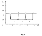
- the time-dependent determined in this way Signal mean value sequence is shown in Figure 1. This The sequence describes the change over time Transparency of the fingers and thus provides additional Information about the user to be identified.
- the characterizes the pulse of the user the period of the Pulses are determined, the time intervals t1, t2, t3 between the minimum values of the curve.
- the pulse rate of a specific user is known and has been saved, there is the possibility of Comparison of this data and thus the user identification by including the value of the pulse rate.
- FIG. 2 shows the structural scheme of the invention Device for user identification shown.
- the device consists of the light pulse source 1, the camera 2 with a photosensitive unit 3, designed as a CCD, and one Control module 4 for controlling the photosensitive unit.
- the camera has a fiber optic input surface 5 for Edition of the user finger 6.
- the device has a pulse generator 7 for controlling the lighting element and a block 8 for information processing.
- the lighting element 1 consists of light diodes, with which red light from the visible range of the spectrum is produced. It is located in front of the entrance surface 5 at a distance that on the one hand allows between him and the input surface 5 the finger of the user and on the other hand offers the possibility the finger with the light of the lighting element illuminate.
- a conventional television camera can be used as camera 2 External synchronization and a photosensitive unit in the form of CCDs.
- the fiber optic input surface 5 consists of a fiber optic plate, the fiber diameter each single fiber is six microns and an aperture of at least 1.0 at a wavelength of 546 nanometers having.
- the photosensitive unit 3 as Single area CCD executed.
- the Photosensitive area from two separately controllable Halves consist of each 288 lines contains photosensitive elements. Both halves are open to the light and have one common electronic control. Every line in every Half consists of 512 photosensitive elements.
- On Element of the photosensitive area has the Dimensions 18 microns by 24 microns. It will be with a three-phase control during charge transfer within the photosensitive area and its Output register worked.
- the control block 4 is connected to the via a connecting rail Photosensitive unit 3 connected and has the Task, the charge image built up from the latter read out and convert into standard video signals.
- Generation of the standard video signals is in the Control block also a generator for Image sync signals (not shown in the figure).
- the output of this generator represents one of the outputs of the Camera and is with the input of the pulse generator 7th connected.
- the pulse generator 7 generates from the image synchronization signals the switch-on pulses for the lighting element.
- the pulse generator Image sync signals only amplified or from them Pulses of shorter duration with a given one Shift to the image sync signals and one predetermined amplitude generated.
- the exit of the Pulse generator 7 is with the light-emitting diodes Pulse lighting element 1 connected.
- the pulse generator 7 can be omitted and the Output of the generator for picture synchronizing signals immediately be connected to the lighting element 1. It exists as well as the possibility of the camera and that Lighting element via an external synchronous signal source or via the pulses of the AC network synchronize.
- the other output of the camera 2 is connected to the input of the Information processing block 8 connected.
- the Information processing block 8 is in the form of a Multimedia personal computer running with a Video blaster card, for example SE100 from Creative Labs, for receiving the coming from the camera Video signal is equipped.
- Video blaster card for example SE100 from Creative Labs
- Dactyloscopic identification programs are used, such as they are used in known identification devices. Additional programs can also be installed have the task of unauthorized access to the computer to prevent or, for example, the user's pulse determine (see following functional description of the Device). The functions mentioned here does this through the Zealandian company OPAK distributed program PCLOCK from.
- the lighting element 1, the camera 2 and the pulse generator 7 can constructively in the form of a single block (as Dactyloskop) be executed in the housing of the PC (Information block 8), for example in a 5.25 "rack is housed.
- a dactyloscope "DELSY” will currently manufactured by the Russian company ELSYS.
- the device works as follows.
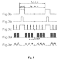
- the image synchronization signal generator (not shown in the figures) generates image synchronization signals at the output of the camera (see FIG. 3a).
- the period and duration of these impulses correspond to the usual television standards.
- it can be signals of the CCIR standard with a field frequency of 50 sec -1 and a number of image lines of 625.
- the duration tb of the signal peak of the picture synchronizing signal is 1.6 milliseconds and the signal period Tfr is twenty milliseconds.
- other television standards can also be used, for example with a field frequency of 60 sec -1 and a number of picture lines of 525.
- the picture synchronous signals are passed to the input of the pulse generator 7 which converts them into signals of shorter duration and one Excitation of the lighting element converts sufficient amplitude.
- the output signals of the pulse generator 7 are shown in Figure 3b.
- the lighting element 1 generates light pulses which correspond to the excitation signals coming from the pulse generator 7.
- the user puts his finger on the fiber optic Surface of the camera 2 on.
- the finger is from Light pulses are illuminated, causing the surface of the photosensitive unit 3 a dactyloscopic Figure emerges.
- the time intervals tb describe the time in which the Camera is in the image build-up phase, i.e. during the dctyloscopic image is based on the time intervals tb the surface of the photosensitive unit in the form of a Charge pattern built up.
- the in Figure 3c and 3d shown in the interval td part of Control signal corresponds to the shift pulse. Through the Shifting impulses will be read line by line Charge pattern guaranteed by known methods.
- the control module 4 will image signal read by the photosensitive unit amplified and converted into a standard video signal.
- the video signal is transferred to the PC, where it passes through the Video blaster (not shown in the figures) digitized and then with existing software is processed.
- the program realizes PCLOCK following processing algorithm:
- An image sequence is analyzed.
- the first serves Image for obtaining the dactyloscopic data, that is there will be the coordinates of the characteristic dactyloscopic features relative to the center of the Papillary line pattern determined.
- the so won Dactyloscopic data are then combined with the one earlier stored dactyloscopic data authorized user (archive of the PCLOCK program) compared.
- the Pulse rate of the user determined. This happens through determining the video signal value for a given one Part of each image in the sequence of images and a subsequent one Analysis of the temporal dependence of these mean values. The the dependency in question is shown in FIG. 1.
- the so Pulse rate values can also be determined using the pulse frequencies stored at an earlier point in time authorized users can be compared.
- the invention can be applied to a wide range different areas of activity of people for Be used - for example as Apartment door lock, in user recognition modules for PCs, in Facilities for reviewing User identification data when accessing computer networks, in Diagnostic devices for different diseases and in Cashless payment system.
- the simplicity the technical implementation and the wide range of applications underline the timeliness of the present invention.
- the invention can be in any range of the People who require user identification is, for example in the field of computer technology, the Medicine, criminalistics, protection and Admission control systems as well as in the area of finance and Banking sector.
Landscapes
- Engineering & Computer Science (AREA)
- Human Computer Interaction (AREA)
- Physics & Mathematics (AREA)
- General Physics & Mathematics (AREA)
- Multimedia (AREA)
- Theoretical Computer Science (AREA)
- Measurement Of The Respiration, Hearing Ability, Form, And Blood Characteristics Of Living Organisms (AREA)
- Control Of Vending Devices And Auxiliary Devices For Vending Devices (AREA)
- Input Circuits Of Receivers And Coupling Of Receivers And Audio Equipment (AREA)
- Collating Specific Patterns (AREA)
- Image Input (AREA)
- Financial Or Insurance-Related Operations Such As Payment And Settlement (AREA)
- Use Of Switch Circuits For Exchanges And Methods Of Control Of Multiplex Exchanges (AREA)
- Image Processing (AREA)
- Crystals, And After-Treatments Of Crystals (AREA)
Applications Claiming Priority (3)
| Application Number | Priority Date | Filing Date | Title |
|---|---|---|---|
| RU96124447/09A RU2154301C2 (ru) | 1996-12-19 | 1996-12-19 | Дактилоскопическая система идентификации изображения |
| RU96124447 | 1996-12-19 | ||
| PCT/RU1997/000105 WO1998027509A1 (fr) | 1996-12-19 | 1997-04-04 | Procede et appareil d'identification de l'utilisateur |
Publications (3)
| Publication Number | Publication Date |
|---|---|
| EP0950977A1 EP0950977A1 (de) | 1999-10-20 |
| EP0950977A4 EP0950977A4 (de) | 2000-01-12 |
| EP0950977B1 true EP0950977B1 (de) | 2002-12-18 |
Family
ID=20188605
Family Applications (1)
| Application Number | Title | Priority Date | Filing Date |
|---|---|---|---|
| EP97921007A Expired - Lifetime EP0950977B1 (de) | 1996-12-19 | 1997-04-04 | Verfahren und gerät zur nutzeridentifikation |
Country Status (8)
| Country | Link |
|---|---|
| EP (1) | EP0950977B1 (da) |
| AT (1) | ATE230137T1 (da) |
| AU (1) | AU2716497A (da) |
| DE (1) | DE59709033D1 (da) |
| DK (1) | DK0950977T3 (da) |
| ES (1) | ES2188939T3 (da) |
| RU (1) | RU2154301C2 (da) |
| WO (1) | WO1998027509A1 (da) |
Families Citing this family (7)
| Publication number | Priority date | Publication date | Assignee | Title |
|---|---|---|---|---|
| FR2763720B1 (fr) * | 1997-05-21 | 1999-07-16 | Sagem | Capteur optique d'empreinte digitale a eclairage impulsionnel |
| DE19860068C2 (de) * | 1998-12-23 | 2002-10-17 | Delsy Electronic Components Ag | Vorrichtung zur Personenidentifikation |
| RU2195020C2 (ru) * | 2000-01-11 | 2002-12-20 | Многопрофильное предприятие ООО "Элсис" | Способ и устройство идентификации пользователя |
| US6895104B2 (en) * | 2001-02-16 | 2005-05-17 | Sac Technologies, Inc. | Image identification system |
| RU2199943C2 (ru) * | 2001-02-16 | 2003-03-10 | Многопрофильное предприятие ООО "Элсис" | Способ и устройство регистрации пульсовой волны и биометрическая система |
| US9070024B2 (en) | 2012-07-23 | 2015-06-30 | International Business Machines Corporation | Intelligent biometric identification of a participant associated with a media recording |
| RU2699507C1 (ru) * | 2018-11-01 | 2019-09-05 | Федеральное государственное бюджетное образовательное учреждение высшего образования "Кубанский государственный аграрный университет имени И.Т. Трубилина" | Мобильное устройство для выявления следов рук |
Citations (1)
| Publication number | Priority date | Publication date | Assignee | Title |
|---|---|---|---|---|
| US4708882A (en) * | 1984-12-27 | 1987-11-24 | Kawasaki Steel Corporation | Method for detecting fingerprints using a laser and an apparatus therefor |
Family Cites Families (12)
| Publication number | Priority date | Publication date | Assignee | Title |
|---|---|---|---|---|
| FR2529453A1 (fr) * | 1982-06-30 | 1984-01-06 | Becquet Jacqueline | Appareil de controle du rythme cardiaque a detection plethysmographique |
| JPS61240383A (ja) * | 1985-04-17 | 1986-10-25 | Kawasaki Steel Corp | 指紋検出装置 |
| JPS62127979A (ja) * | 1985-11-28 | 1987-06-10 | Matsushita Electric Ind Co Ltd | バ−コ−ドリ−ダの投光光源制御方法 |
| WO1989002722A1 (en) * | 1987-09-24 | 1989-04-06 | Siemens Aktiengesellschaft | Fingerprint sensing device |
| JPH04252383A (ja) * | 1990-07-27 | 1992-09-08 | Ezel Inc | 指紋撮影装置 |
| US5230025A (en) * | 1990-08-31 | 1993-07-20 | Digital Biometrics, Inc. | Method and apparatus for capturing skin print images |
| FR2674051A1 (fr) * | 1991-03-14 | 1992-09-18 | Gemplus Card Int | Dispositif d'identification d'une personne, notamment par detection d'empreinte digitale. |
| RU2031625C1 (ru) * | 1992-01-31 | 1995-03-27 | Виктор Альбертович Минкин | Способ получения контактного изображения объекта |
| DE4222387C2 (de) * | 1992-07-08 | 1994-06-30 | Stockburger H | Verfahren und Vorrichtung zur Identifikation der jeweiligen Raumstruktur eines Prüfobjektes |
| JP3045629B2 (ja) * | 1993-02-17 | 2000-05-29 | 三菱電機株式会社 | 凹凸パターン検出装置 |
| US5550366A (en) * | 1994-06-20 | 1996-08-27 | Roustaei; Alexander | Optical scanner with automatic activation |
| US5548394A (en) * | 1995-03-16 | 1996-08-20 | Printrak International Inc. | Scanning fingerprint reading |
-
1996
- 1996-12-19 RU RU96124447/09A patent/RU2154301C2/ru not_active IP Right Cessation
-
1997
- 1997-04-04 WO PCT/RU1997/000105 patent/WO1998027509A1/ru not_active Ceased
- 1997-04-04 EP EP97921007A patent/EP0950977B1/de not_active Expired - Lifetime
- 1997-04-04 DE DE59709033T patent/DE59709033D1/de not_active Expired - Fee Related
- 1997-04-04 AT AT97921007T patent/ATE230137T1/de not_active IP Right Cessation
- 1997-04-04 ES ES97921007T patent/ES2188939T3/es not_active Expired - Lifetime
- 1997-04-04 AU AU27164/97A patent/AU2716497A/en not_active Abandoned
- 1997-04-04 DK DK97921007T patent/DK0950977T3/da active
Patent Citations (1)
| Publication number | Priority date | Publication date | Assignee | Title |
|---|---|---|---|---|
| US4708882A (en) * | 1984-12-27 | 1987-11-24 | Kawasaki Steel Corporation | Method for detecting fingerprints using a laser and an apparatus therefor |
Also Published As
| Publication number | Publication date |
|---|---|
| RU2154301C2 (ru) | 2000-08-10 |
| EP0950977A4 (de) | 2000-01-12 |
| EP0950977A1 (de) | 1999-10-20 |
| ATE230137T1 (de) | 2003-01-15 |
| DE59709033D1 (de) | 2003-01-30 |
| DK0950977T3 (da) | 2003-04-14 |
| AU2716497A (en) | 1998-07-15 |
| ES2188939T3 (es) | 2003-07-01 |
| WO1998027509A1 (fr) | 1998-06-25 |
Similar Documents
| Publication | Publication Date | Title |
|---|---|---|
| DE69934068T2 (de) | Bestimmung der position von augen durch blitzreflexerkennung und korrektur von defekten in einem aufgenommenen bild | |
| DE10158990C1 (de) | Videoüberwachungssystem | |
| EP3047424B1 (de) | Vorrichtung, system und verfahren zum identifizieren einer person | |
| DE60220494T2 (de) | Verfahren zur Iriserkennung und System unter Verwendung desselben | |
| EP1147494B1 (de) | Verfahren und system zur fälschungssicherung bei biometrischer personenerkennung | |
| DE60207863T2 (de) | Vorrichtung und Verfahren zur Gesichtserkennung | |
| DE69837233T2 (de) | Verfahren und Gerät zur Bestimmung der Augenposition in einem Bild | |
| DE60209760T2 (de) | Gesichtsbilderzeugungssystem zur bildaufnahme und automatisierte bestätigung der identität | |
| DE69608218T2 (de) | Gerät zur Erkennung von Personen | |
| DE3687710T2 (de) | Abtasten einer charakteristik mit ausgeglichenen bildelementen. | |
| DE69830611T2 (de) | Verfahren zur beleuchtung und bilddarstellung von augen mit brille bei anwendung von mehrfachbeleuchtungsquellen | |
| DE2801927C2 (da) | ||
| DE69600881T2 (de) | Verfahren und system zur aufnahme digitaler kamerabilder | |
| EP3611659B1 (de) | Vorrichtung zum bereitstellen einer mehrzahl von biometrischen merkmalen einer mehrzahl von personen einer personengruppe | |
| DE2627981C3 (de) | Identifizierungssystem mittels Fingerabdrucken | |
| DE112020006938T5 (de) | Kamera-mehrzeilen-zeitteilungs-belichtungsverarbeitungsverfahren und -system | |
| EP2422325A1 (de) | Selbstbedienungsterminal mit mindestens einer bilddaten erzeugenden kamera zum erkennen von manipulationsversuchen | |
| DE102013009474A1 (de) | Vorrichtung zur automatischen Verifizierung eines Identitätsdokuments einer Person und Verfahren zum Erzeugen von Erkennungsdaten einer Person zur Verwendung in einer automatisierten Identitätskontrollstation | |
| EP0950977A1 (de) | Verfahren und gerät zur nutzeridentifikation | |
| EP4075396B1 (de) | Verfahren und anordnung zur optischen erfassung eines kopfes einer person | |
| EP3839815A1 (de) | Vorrichtung und verfahren zum bestimmen eines biometrischen merkmals eines gesichts einer person | |
| DE69422245T2 (de) | Verfahren und Gerät zur Analyse von Teilchendurchflussbildern | |
| AT521934A1 (de) | Verfahren zur Erfassung von Fingerabdrücken | |
| DE69709406T2 (de) | Vorrichtung zum messen der aufmerksamkeit von probanden bezüglich eines dargebotenen gegenstandes | |
| DE10153484B4 (de) | Video-/Audio-System und Auswertungsverfahren für Video-/Audio-Daten |
Legal Events
| Date | Code | Title | Description |
|---|---|---|---|
| PUAI | Public reference made under article 153(3) epc to a published international application that has entered the european phase |
Free format text: ORIGINAL CODE: 0009012 |
|
| 17P | Request for examination filed |
Effective date: 19990617 |
|
| AK | Designated contracting states |
Kind code of ref document: A1 Designated state(s): AT BE CH DE DK ES FI FR GB GR IE IT LI LU MC NL PT SE |
|
| AX | Request for extension of the european patent |
Free format text: RO PAYMENT 19990617;SI PAYMENT 19990617 |
|
| A4 | Supplementary search report drawn up and despatched |
Effective date: 19991126 |
|
| AK | Designated contracting states |
Kind code of ref document: A4 Designated state(s): AT BE CH DE DK ES FI FR GB GR IE IT LI LU MC NL PT SE |
|
| RIC1 | Information provided on ipc code assigned before grant |
Free format text: 7G 06K 9/00 A, 7G 06K 9/36 B, 7G 06K 9/46 B, 7G 06K 9/62 B, 7G 07C 9/00 B |
|
| RAP1 | Party data changed (applicant data changed or rights of an application transferred) |
Owner name: DELSY ELECTRONIC COMPONENTS AG |
|
| 17Q | First examination report despatched |
Effective date: 20010619 |
|
| GRAG | Despatch of communication of intention to grant |
Free format text: ORIGINAL CODE: EPIDOS AGRA |
|
| GRAG | Despatch of communication of intention to grant |
Free format text: ORIGINAL CODE: EPIDOS AGRA |
|
| GRAH | Despatch of communication of intention to grant a patent |
Free format text: ORIGINAL CODE: EPIDOS IGRA |
|
| GRAH | Despatch of communication of intention to grant a patent |
Free format text: ORIGINAL CODE: EPIDOS IGRA |
|
| GRAA | (expected) grant |
Free format text: ORIGINAL CODE: 0009210 |
|
| AK | Designated contracting states |
Kind code of ref document: B1 Designated state(s): AT BE CH DE DK ES FI FR GB GR IE IT LI LU MC NL PT SE |
|
| AX | Request for extension of the european patent |
Free format text: RO PAYMENT 19990617;SI PAYMENT 19990617 |
|
| PG25 | Lapsed in a contracting state [announced via postgrant information from national office to epo] |
Ref country code: IE Free format text: LAPSE BECAUSE OF FAILURE TO SUBMIT A TRANSLATION OF THE DESCRIPTION OR TO PAY THE FEE WITHIN THE PRESCRIBED TIME-LIMIT Effective date: 20021218 |
|
| REF | Corresponds to: |
Ref document number: 230137 Country of ref document: AT Date of ref document: 20030115 Kind code of ref document: T |
|
| REG | Reference to a national code |
Ref country code: GB Ref legal event code: FG4D Free format text: NOT ENGLISH |
|
| REG | Reference to a national code |
Ref country code: CH Ref legal event code: EP |
|
| REG | Reference to a national code |
Ref country code: IE Ref legal event code: FG4D Free format text: GERMAN |
|
| REF | Corresponds to: |
Ref document number: 59709033 Country of ref document: DE Kind code of ref document: P Date of ref document: 20030130 |
|
| PGFP | Annual fee paid to national office [announced via postgrant information from national office to epo] |
Ref country code: SE Payment date: 20030221 Year of fee payment: 7 |
|
| PGFP | Annual fee paid to national office [announced via postgrant information from national office to epo] |
Ref country code: CH Payment date: 20030314 Year of fee payment: 7 |
|
| PGFP | Annual fee paid to national office [announced via postgrant information from national office to epo] |
Ref country code: PT Payment date: 20030321 Year of fee payment: 7 |
|
| PGFP | Annual fee paid to national office [announced via postgrant information from national office to epo] |
Ref country code: GB Payment date: 20030325 Year of fee payment: 7 |
|
| PGFP | Annual fee paid to national office [announced via postgrant information from national office to epo] |
Ref country code: FR Payment date: 20030328 Year of fee payment: 7 |
|
| REG | Reference to a national code |
Ref country code: DK Ref legal event code: T3 |
|
| PGFP | Annual fee paid to national office [announced via postgrant information from national office to epo] |
Ref country code: NL Payment date: 20030416 Year of fee payment: 7 |
|
| PGFP | Annual fee paid to national office [announced via postgrant information from national office to epo] |
Ref country code: GR Payment date: 20030422 Year of fee payment: 7 Ref country code: ES Payment date: 20030422 Year of fee payment: 7 |
|
| PGFP | Annual fee paid to national office [announced via postgrant information from national office to epo] |
Ref country code: AT Payment date: 20030424 Year of fee payment: 7 |
|
| REG | Reference to a national code |
Ref country code: GR Ref legal event code: EP Ref document number: 20030401069 Country of ref document: GR |
|
| PGFP | Annual fee paid to national office [announced via postgrant information from national office to epo] |
Ref country code: BE Payment date: 20030425 Year of fee payment: 7 Ref country code: FI Payment date: 20030425 Year of fee payment: 7 Ref country code: DK Payment date: 20030425 Year of fee payment: 7 |
|
| PGFP | Annual fee paid to national office [announced via postgrant information from national office to epo] |
Ref country code: LU Payment date: 20030429 Year of fee payment: 7 |
|
| PG25 | Lapsed in a contracting state [announced via postgrant information from national office to epo] |
Ref country code: MC Free format text: LAPSE BECAUSE OF NON-PAYMENT OF DUE FEES Effective date: 20030430 |
|
| REG | Reference to a national code |
Ref country code: CH Ref legal event code: NV Representative=s name: SAEGER & PARTNER |
|
| GBT | Gb: translation of ep patent filed (gb section 77(6)(a)/1977) |
Effective date: 20030411 |
|
| PGFP | Annual fee paid to national office [announced via postgrant information from national office to epo] |
Ref country code: DE Payment date: 20030626 Year of fee payment: 7 |
|
| REG | Reference to a national code |
Ref country code: ES Ref legal event code: FG2A Ref document number: 2188939 Country of ref document: ES Kind code of ref document: T3 |
|
| ET | Fr: translation filed | ||
| REG | Reference to a national code |
Ref country code: IE Ref legal event code: FD4D Ref document number: 0950977E Country of ref document: IE |
|
| PLBE | No opposition filed within time limit |
Free format text: ORIGINAL CODE: 0009261 |
|
| STAA | Information on the status of an ep patent application or granted ep patent |
Free format text: STATUS: NO OPPOSITION FILED WITHIN TIME LIMIT |
|
| 26N | No opposition filed |
Effective date: 20030919 |
|
| PG25 | Lapsed in a contracting state [announced via postgrant information from national office to epo] |
Ref country code: LU Free format text: LAPSE BECAUSE OF NON-PAYMENT OF DUE FEES Effective date: 20040404 Ref country code: GB Free format text: LAPSE BECAUSE OF NON-PAYMENT OF DUE FEES Effective date: 20040404 Ref country code: FI Free format text: LAPSE BECAUSE OF NON-PAYMENT OF DUE FEES Effective date: 20040404 Ref country code: AT Free format text: LAPSE BECAUSE OF NON-PAYMENT OF DUE FEES Effective date: 20040404 |
|
| PG25 | Lapsed in a contracting state [announced via postgrant information from national office to epo] |
Ref country code: SE Free format text: LAPSE BECAUSE OF NON-PAYMENT OF DUE FEES Effective date: 20040405 Ref country code: ES Free format text: LAPSE BECAUSE OF NON-PAYMENT OF DUE FEES Effective date: 20040405 |
|
| PG25 | Lapsed in a contracting state [announced via postgrant information from national office to epo] |
Ref country code: LI Free format text: LAPSE BECAUSE OF NON-PAYMENT OF DUE FEES Effective date: 20040430 Ref country code: DK Free format text: LAPSE BECAUSE OF NON-PAYMENT OF DUE FEES Effective date: 20040430 Ref country code: CH Free format text: LAPSE BECAUSE OF NON-PAYMENT OF DUE FEES Effective date: 20040430 Ref country code: BE Free format text: LAPSE BECAUSE OF NON-PAYMENT OF DUE FEES Effective date: 20040430 |
|
| PG25 | Lapsed in a contracting state [announced via postgrant information from national office to epo] |
Ref country code: PT Free format text: LAPSE BECAUSE OF NON-PAYMENT OF DUE FEES Effective date: 20041015 |
|
| BERE | Be: lapsed |
Owner name: *DELSY ELECTRONIC COMPONENTS A.G. Effective date: 20040430 |
|
| PG25 | Lapsed in a contracting state [announced via postgrant information from national office to epo] |
Ref country code: NL Free format text: LAPSE BECAUSE OF NON-PAYMENT OF DUE FEES Effective date: 20041101 |
|
| PG25 | Lapsed in a contracting state [announced via postgrant information from national office to epo] |
Ref country code: GR Free format text: LAPSE BECAUSE OF NON-PAYMENT OF DUE FEES Effective date: 20041103 Ref country code: DE Free format text: LAPSE BECAUSE OF NON-PAYMENT OF DUE FEES Effective date: 20041103 |
|
| GBPC | Gb: european patent ceased through non-payment of renewal fee | ||
| EUG | Se: european patent has lapsed | ||
| REG | Reference to a national code |
Ref country code: CH Ref legal event code: PL |
|
| PG25 | Lapsed in a contracting state [announced via postgrant information from national office to epo] |
Ref country code: FR Free format text: LAPSE BECAUSE OF NON-PAYMENT OF DUE FEES Effective date: 20041231 |
|
| NLV4 | Nl: lapsed or anulled due to non-payment of the annual fee |
Effective date: 20041101 |
|
| REG | Reference to a national code |
Ref country code: FR Ref legal event code: ST |
|
| PG25 | Lapsed in a contracting state [announced via postgrant information from national office to epo] |
Ref country code: IT Free format text: LAPSE BECAUSE OF NON-PAYMENT OF DUE FEES;WARNING: LAPSES OF ITALIAN PATENTS WITH EFFECTIVE DATE BEFORE 2007 MAY HAVE OCCURRED AT ANY TIME BEFORE 2007. THE CORRECT EFFECTIVE DATE MAY BE DIFFERENT FROM THE ONE RECORDED. Effective date: 20050404 |
|
| REG | Reference to a national code |
Ref country code: ES Ref legal event code: FD2A Effective date: 20040405 |