EP0951113A2 - Rectangular case for electrical or electronic components - Google Patents
Rectangular case for electrical or electronic components Download PDFInfo
- Publication number
- EP0951113A2 EP0951113A2 EP99103159A EP99103159A EP0951113A2 EP 0951113 A2 EP0951113 A2 EP 0951113A2 EP 99103159 A EP99103159 A EP 99103159A EP 99103159 A EP99103159 A EP 99103159A EP 0951113 A2 EP0951113 A2 EP 0951113A2
- Authority
- EP
- European Patent Office
- Prior art keywords
- frame
- front panel
- web
- front plate
- groove
- Prior art date
- Legal status (The legal status is an assumption and is not a legal conclusion. Google has not performed a legal analysis and makes no representation as to the accuracy of the status listed.)
- Granted
Links
- 239000002184 metal Substances 0.000 claims abstract description 4
- 239000002991 molded plastic Substances 0.000 claims description 3
- 230000000284 resting effect Effects 0.000 claims description 3
- 230000001154 acute effect Effects 0.000 claims description 2
- 238000010276 construction Methods 0.000 abstract description 2
- 238000007789 sealing Methods 0.000 description 4
- 239000004033 plastic Substances 0.000 description 2
- 230000001419 dependent effect Effects 0.000 description 1
- 238000004519 manufacturing process Methods 0.000 description 1
- 230000007246 mechanism Effects 0.000 description 1
Images

Classifications
-
- H—ELECTRICITY
- H02—GENERATION; CONVERSION OR DISTRIBUTION OF ELECTRIC POWER
- H02B—BOARDS, SUBSTATIONS OR SWITCHING ARRANGEMENTS FOR THE SUPPLY OR DISTRIBUTION OF ELECTRIC POWER
- H02B1/00—Frameworks, boards, panels, desks, casings; Details of substations or switching arrangements
- H02B1/26—Casings; Parts thereof or accessories therefor
- H02B1/28—Casings; Parts thereof or accessories therefor dustproof, splashproof, drip-proof, waterproof or flameproof
-
- H—ELECTRICITY
- H02—GENERATION; CONVERSION OR DISTRIBUTION OF ELECTRIC POWER
- H02B—BOARDS, SUBSTATIONS OR SWITCHING ARRANGEMENTS FOR THE SUPPLY OR DISTRIBUTION OF ELECTRIC POWER
- H02B1/00—Frameworks, boards, panels, desks, casings; Details of substations or switching arrangements
- H02B1/26—Casings; Parts thereof or accessories therefor
- H02B1/40—Wall-mounted casings; Parts thereof or accessories therefor
Definitions
- the present invention relates to a rectangular housing for receiving electrical or electronic components with a side wall forming and made of sheet metal Frame and a front panel attached to the frame.
- the present invention has for its object a housing of the generic type To create a way in which a simple and properly sealed down the Front panel on the frame is possible.
- the frame on the front panel facing side with an open to the outside and by multiple folds formed, undercut groove is provided that the groove through a on the front panel Assigning end web, a central web running parallel to the front panel and one further, approximately perpendicular to the front panel side web is limited, and that the Provide a face seal on the side facing the frame in the frame is, which rests on the front edge of the end web, the front panel as a whole is fixed against the frame by several fastening screws.
- This construction enables the front panel to be easily attached to the housing or to determine its framework while achieving a flawless Sealing, both fixing the front panel from the outside, as well is possible from the inside without causing a sealing problem.
- the fastening screws step through the front panel and into nuts that can be moved within the receiving groove be screwed in.
- the openings in the front panel through which the screws pass are located must be outside the sealed area between the front panel and frame, so that a separate sealing of the screw area is not required.
- the fastening screws can be used as screw bolts be formed on the inside of the front panel facing the housing are attached and each pass through one leg of an L-shaped support bracket, the with the leg penetrated by the screw bolt on the central web and with his other leg stands up directly on the front panel, with each screw bolt a nut is screwed on, which rests against the one resting on the central web Leg of the support bracket is tightened.
- the fastening screws are within the circumferential one Seal of the front panel lying frame area, but penetrate the front panel itself not, so that no sealing problems arise in this case either.
- complicated fastening mechanisms are not required, but only simple fastening screws and, if necessary, also easy to manufacture support brackets.
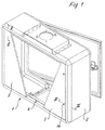
- Figure 1 with the reference numeral 1 is an approximately rectangular housing for receiving Designated (not shown) electrical or electronic components, which one made of sheet metal and the side walls of the housing 1 forming frame (2) and a Front panel 3, which was shown broken open in Figure 1, to have a look into the To allow interior of the housing 1.
- Designated not shown
- electrical or electronic components which one made of sheet metal and the side walls of the housing 1 forming frame (2) and a Front panel 3, which was shown broken open in Figure 1, to have a look into the To allow interior of the housing 1.
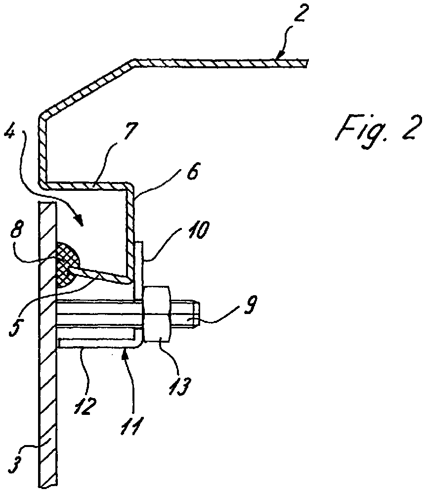
- the frame 2 is on the side facing the front panel 3 with an open toward the outside and equipped by multiple folds, undercut groove 4, what is particularly clear from Figures 2 and 3.
- This undercut groove 4 is delimited by an end web facing the front plate 3 5, a central web 6 running parallel to the front plate 3 and a side web 7, which in turn extends approximately perpendicular to the front panel 3.
- the final web 5 runs opposite the front panel 3 inclined and includes an acute angle with the central web 6, so that an undercut of the groove 4 is given.
- the front plate 3 has a circumferential on its rear side facing the frame 2 Seal 8, which is firmly connected to the front panel 3, for. B. this seal 8 the front panel 3 be glued on.
- this seal 8 lies sealingly on the front edge of the final web 5.
- Figures 2 and 3 show two different ways of determining the Front plate 3 opposite the frame 2.
- FIG 2 it is shown that the front panel 3 on the inside facing the housing is equipped with bolts 9, which are welded to the front panel 3, for example are.
- These bolts 9 pass through a leg 10 of a support bracket 11 while the other leg 12 of this support bracket 11 with its front edge directly on the Front plate 3 stands up.
- the leg 10 penetrated by the screw bolts 9 of each support angle 11 lies on the middle web 6.
- Nuts 13 are screwed onto the bolts 9, against the leg 10 of the support bracket 11 resting on the central web 6 get dressed by.
- the front panel 3 is firmly tightened to the frame 2, wherein the seal 8 is tightened accordingly against the front end edge of the end web 5 becomes.
- the front plate 3 is fixed by fastening screws 14, which pass through the front panel 3 and screwed into nuts 13 are which are slidably disposed within the groove 4.
- These are advantageously Nuts 13 inserted into a molded plastic part 15, which has a resilient leg 16 Is provided.
- the plastic molded parts 15 are the shape of the cross section undercut groove 4 adapted and frictionally due to the resilient leg 16 in the groove 4 held.
- the nuts 13 are secured against rotation within the plastic molded parts 15 used.
- the fastening screws 14 run outside of the sealed one Area between the front panel 3 and the frame 2, so that the openings in the area of the front panel 3 do not have to be sealed separately again in order to to ensure an overall tight connection between the front plate 3 and frame 2.
Landscapes
- Engineering & Computer Science (AREA)
- Power Engineering (AREA)
- Casings For Electric Apparatus (AREA)
- Compositions Of Macromolecular Compounds (AREA)
- Laminated Bodies (AREA)
- Structure Of Receivers (AREA)
- Coils Or Transformers For Communication (AREA)
Abstract
Rechteckiges Gehäuse zur Aufnahme elektrischer oder elektronischer Bauteile.
Gegenstand der Erfindung ist ein rechteckiges Gehäuse (1) zur Aufnahme elektrischer
oder elektronischer Bauteile. Das Gehäuse umfaßt einen die Seitenwände bildenden
und aus Blech gefertigten Rahmen (2) und eine am Rahmen (2) festgelegte
Frontplatte (3). Der Rahmen (2) ist auf der der Frontplatte (3) zugewandten Seite
mit einer nach außen hin offenen und durch mehfache Abkantungen gebildeten,
hinterschnittenen Nut (4) versehen. Die Nut (4) ist durch einen auf die Frontplatte
(3) zuweisenden Abschlußsteg (5), einen parallel zur Frontplatte (3) verlaufenden
Mittelsteg (6) und einen etwa lotrecht zur Frontplatte (3) verlaufenden Seitensteg
(7) begrenzt. Die Frontplatte (3) ist auf ihrer dem Rahmen (2) zugewandten Seite
mit einer umlaufenden Dichtung (8) versehen, welche auf der Stirnkante des Abschlußsteges
(5) aufliegt. Die Frontplatte (3) selbst ist insgesamt durch mehrere Befestigungsschrauben
(9, 14) gegen den Rahmen (2) festgelegt.
Diese Konstruktion ermöglicht eine einfache Festlegung der Frontplatte (3) am Gehäuse
(1) bzw. an dessen Rahmen (2) unter gleichzeitiger Erzielung einer einwandfreien
Abdichtung.
Description
Die vorliegende Erfindung betrifft ein rechteckiges Gehäuse zur Aufnahme elektrischer oder elektronischer Bauteile mit einem die Seitenwand bildenden und aus Blech gefertigten Rahmen und einer am Rahmen festgelegten Frontplatte.The present invention relates to a rectangular housing for receiving electrical or electronic components with a side wall forming and made of sheet metal Frame and a front panel attached to the frame.
Der vorliegenden Erfindung liegt die Aufgabe zugrunde, ein Gehäuse der gattungsgemäßen Art zu schaffen, bei dem eine einfache und einwandfrei abgedichtete Festlegung der Frontplatte am Rahmen möglich ist.The present invention has for its object a housing of the generic type To create a way in which a simple and properly sealed down the Front panel on the frame is possible.
Diese Aufgabe wird erfindungsgemäß dadurch gelöst, daß der Rahmen auf der der Frontplatte zugewandten Seite mit einer nach außen hin offenen und durch mehrfache Abkantung gebildeten, hinterschnittenen Nut versehen ist, daß die Nut durch einen auf die Frontplatte zuweisenden Abschlußsteg, einen parallel zur Frontplatte verlaufenden Mittelsteg und einen weiteren, etwa lotrecht zur Frontplatte verlaufenden Seitensteg begrenzt ist, und daß die Frontplatte auf ihrer im Rahmen zugewandten Seite mit einer umlaufenden Dichtung versehen ist, welche auf der Stirnkante des Abschlußsteges aufliegt, wobei die Frontplatte insgesamt durch mehrere Befestigungsschrauben gegen den Rahmen festgelegt ist.This object is achieved in that the frame on the front panel facing side with an open to the outside and by multiple folds formed, undercut groove is provided that the groove through a on the front panel Assigning end web, a central web running parallel to the front panel and one further, approximately perpendicular to the front panel side web is limited, and that the Provide a face seal on the side facing the frame in the frame is, which rests on the front edge of the end web, the front panel as a whole is fixed against the frame by several fastening screws.
Diese Konstruktion ermöglicht es, die Frontplatte auf einfache Art und Weise am Gehäuse bzw. an dessen Rahmen festzulegen unter gleichzeitiger Erzielung einer einwandfreien Abdichtung, wobei sowohl eine Festlegung der Frontplatte von ihrer Außenseite her, wie auch von der Innenseite her möglich ist, ohne daß dadurch ein Dichtungsproblem entsteht.This construction enables the front panel to be easily attached to the housing or to determine its framework while achieving a flawless Sealing, both fixing the front panel from the outside, as well is possible from the inside without causing a sealing problem.
So können beispielsweise nach einem weiteren Gedanken der Erfindung die Befestigungsschrauben die Frontplatte durchtreten und in innerhalb der Aufnahmenut verschiebbare Muttern eingeschraubt sein.For example, according to a further idea of the invention, the fastening screws step through the front panel and into nuts that can be moved within the receiving groove be screwed in.
In diesem Falle liegen die Durchbrechungen der Frontplatte, durch die die Schrauben hin-durchgeführt werden müssen, außerhalb des abgedichteten Bereiches zwischen Frontplatte und Rahmen, so daß eine separate Abdichtung des Schraubbereiches nicht erforderlich ist.In this case, the openings in the front panel through which the screws pass are located must be outside the sealed area between the front panel and frame, so that a separate sealing of the screw area is not required.
Nach einem anderen Gedanken der Erfindung können die Befestigungsschrauben als Schraubenbolzen ausgebildet sein, die an der dem Gehäuse zugewandten Innenseite der Frontplatte befestigt sind und jeweils einen Schenkel eines L-förmigen Stützwinkels durchtreten, der sich mit dem vom Schraubenbolzen durchtretenen Schenkel auf dem Mittelsteg abstützt und mit seinem anderen Schenkel unmittelbar auf der Frontplatte aufsteht, wobei auf jeden Schraubenbolzen eine Mutter aufgeschraubt ist, welche gegen den auf den Mittelsteg aufliegenden Schenkel des Stützwinkels festgezogen ist.According to another concept of the invention, the fastening screws can be used as screw bolts be formed on the inside of the front panel facing the housing are attached and each pass through one leg of an L-shaped support bracket, the with the leg penetrated by the screw bolt on the central web and with his other leg stands up directly on the front panel, with each screw bolt a nut is screwed on, which rests against the one resting on the central web Leg of the support bracket is tightened.
In diesem Falle liegen die Befestigungsschrauben zwar innerhalb der durch die umlaufende Dichtung der Frontplatte liegenden Rahmenbereiches, durchtreten aber die Frontplatte selbst nicht, so daß auch in diesem Falle keinerlei Dichtprobleme entstehen. Außerdem sind in beiden Fällen komplizierte Befestigungsmechanismen nicht erforderlich, sondern lediglich einfache Befestigungsschrauben und ggfs. ebenfalls einfach herstellbare Stützwinkel.In this case, the fastening screws are within the circumferential one Seal of the front panel lying frame area, but penetrate the front panel itself not, so that no sealing problems arise in this case either. In addition, in In both cases, complicated fastening mechanisms are not required, but only simple fastening screws and, if necessary, also easy to manufacture support brackets.
Weitere Merkmale der Erfindung sind Gegenstand weiterer Unteransprüche.Further features of the invention are the subject of further dependent claims.
Ausführungsbeispiele der Erfindung sind in den beigefügten Zeichnungen dargestellt und werden im folgenden näher beschrieben.Embodiments of the invention are shown in the accompanying drawings are described in more detail below.
Es zeigen:
- Figur 1
- Eine perspektivische Darstellung eines erfindungsgemäßen Gehäuses mit zwei verschiedenen Möglichkeiten der Befestigung einer Frontplatte,
Figur 2- einen Teilschnitt nach der Linie II-II in Figur 1,
Figur 3- einen Schnitt nach der Linie III-III in Figur 1.
- Figure 1
- A perspective view of a housing according to the invention with two different ways of attaching a front panel,
- Figure 2
- 2 shows a partial section along the line II-II in FIG. 1,
- Figure 3
- a section along the line III-III in Figure 1.
In Figur 1 ist mit dem Bezugszeichen 1 insgesamt ein etwa rechteckiges Gehäuse zur Aufnahme
(nicht dargestellter) elektrischer oder elektronischer Bauteile bezeichnet, welches einen
aus Blech gefertigten und die Seitenwände des Gehäuses 1 bildenden Rahmen (2) und eine
Frontplatte 3 aufweist, die in Figur 1 aufgebrochen dargestellt wurde, um einen Blick in das
Innere des Gehäuses 1 zu ermöglichen.In Figure 1 with the reference numeral 1 is an approximately rectangular housing for receiving
Designated (not shown) electrical or electronic components, which one
made of sheet metal and the side walls of the housing 1 forming frame (2) and a
Der Rahmen 2 ist auf der der Frontplatte 3 zugewandten Seite mit einer nach außen hin offenen
und durch mehrfache Abkantungen gebildeten, hinterschnittenen Nut 4 ausgestattet, was
aus den Figuren 2 und 3 besonders deutlich hervorgeht.The
Diese hinterschnittene Nut 4 wird begrenzt durch einen auf die Frontplatte 3 zuweisenden Abschlußsteg
5, einen parallel zur Frontplatte 3 verlaufenden Mittelsteg 6 sowie einen Seitensteg
7, der wiederum etwa lotrecht zur Frontplatte 3 verläuft. Der Abschlußsteg 5 verläuft gegenüber
der Frontplatte 3 geneigt und schließt mit dem Mittelsteg 6 einen spitzen Winkel ein, so
daß eine Hinterschneidung der Nut 4 gegeben ist.This undercut groove 4 is delimited by an end web facing the
Die Frontplatte 3 weist auf ihrer dem Rahmen 2 zugewandten Rückseite eine umlaufende
Dichtung 8 auf, die fest mit der Frontplatte 3 verbunden ist, z. B. kann diese Dichtung 8 auf
die Frontplatte 3 aufgeklebt sein.The
Diese Dichtung 8 legt sich im montierten Zustand der Frontplatte 3 abdichtend auf die Stirn-kante
des Abschlußsteges 5 auf.In the assembled state of the
Die Figuren 2 und 3 zeigen zwei unterschiedliche Möglichkeiten der Festlegung der
Frontplatte 3 gegenüber dem Rahmen 2.Figures 2 and 3 show two different ways of determining the
In Figur 2 ist dargestellt, daß die Frontplatte 3 an der dem Gehäuse zugewandten Innenseite
mit Schraubenbolzen 9 ausgestattet ist, die beispielsweise an der Frontplatte 3 angeschweißt
sind. Diese Schraubenbolzen 9 durchtreten einen Schenkel 10 eines Stützwinkels 11, während
der andere Schenkel 12 dieses Stützwinkels 11 mit seiner Stirnkante unmittelbar auf der
Frontplatte 3 aufsteht. Der von den Schraubenbolzen 9 durchtretene Schenkel 10 jedes Stütz-winkels
11 liegt auf dem Mittelsteg 6 auf. Auf die Schraubenbolzen 9 werden Muttern 13 aufgeschraubt,
die gegen den auf den Mittelsteg 6 aufliegenden Schenkel 10 des Stützwinkels 11
angezogen werden. Hierdurch wird die Frontplatte 3 fest an den Rahmen 2 angezogen, wobei
die Dichtung 8 entsprechend fest gegen die vordere Stirnkante des Abschlußsteges 5 angezogen
wird.In Figure 2 it is shown that the
Beim Ausführungsbeispiel gemäß Figur 3 erfolgt die Festlegung der Frontplatte 3 durch Befestigungsschrauben
14, welche die Frontplatte 3 durchtreten und in Muttern 13 eingeschraubt
sind, welche innerhalb der Nut 4 verschiebbar angeordnet sind. Vorteilhafterweise sind die
Muttern 13 in ein Kunststofformteil 15 eingesetzt, welches mit einem federnden Schenkel 16
ausgestattet ist.In the exemplary embodiment according to FIG. 3, the
Die Kunststofformteile 15 sind hinsichtlich ihres Querschnittes der Form der
hinterschnittenen Nut 4 angepaßt und aufgrund des federnden Schenkels 16 reibschlüssig in
der Nut 4 gehalten. Die Muttern 13 sind verdrehsicher innerhalb der Kunststofformteile 15
eingesetzt.The plastic molded
Wie Figur 3 deutlich erkennen läßt, verlaufen die Befestigungsschrauben 14 außerhalb des abgedichteten
Bereiches zwischen der Frontplatte 3 und dem Rahmen 2, so daß die Durchbrüche
im Bereich der Frontplatte 3 nicht noch einmal separat abgedichtet werden müssen, um eine
insgesamt dichte Verbindung zwischen Frontplatte 3 und Rahmen 2 zu gewährleisten.As FIG. 3 clearly shows, the
Aufgrund der Gestaltung des Rahmens 2 bestehen, wie vorstehend beschrieben, zwei grundsätzlich
unterschiedliche Möglichkeiten der Befestigung der Frontplatte 3, beide
Möglichkeiten sind aber konstruktiv einfach zu realisieren und gewährleisten in jedem Falle
einen absolut dichten Abschluß zwischen Frontplatte 3 und Rahmen 2.Due to the design of the
Claims (5)
Applications Claiming Priority (2)
| Application Number | Priority Date | Filing Date | Title |
|---|---|---|---|
| DE29806876U DE29806876U1 (en) | 1998-04-17 | 1998-04-17 | Rectangular housing for electrical or electronic components (IV) |
| DE29806876U | 1998-04-17 |
Publications (3)
| Publication Number | Publication Date |
|---|---|
| EP0951113A2 true EP0951113A2 (en) | 1999-10-20 |
| EP0951113A3 EP0951113A3 (en) | 2001-05-09 |
| EP0951113B1 EP0951113B1 (en) | 2006-12-27 |
Family
ID=8055818
Family Applications (1)
| Application Number | Title | Priority Date | Filing Date |
|---|---|---|---|
| EP99103159A Expired - Lifetime EP0951113B1 (en) | 1998-04-17 | 1999-02-18 | Rectangular case for electrical or electronic components |
Country Status (5)
| Country | Link |
|---|---|
| US (1) | US6140580A (en) |
| EP (1) | EP0951113B1 (en) |
| AT (1) | ATE349793T1 (en) |
| DE (1) | DE29806876U1 (en) |
| DK (1) | DK0951113T3 (en) |
Families Citing this family (3)
| Publication number | Priority date | Publication date | Assignee | Title |
|---|---|---|---|---|
| DE29816534U1 (en) * | 1998-09-15 | 1999-04-01 | Klein, Jürgen, Dipl.-Ing., 52159 Roetgen | Terminal box |
| CN106233826A (en) * | 2014-04-14 | 2016-12-14 | 三菱电机株式会社 | Casing |
| US10779422B2 (en) * | 2017-09-18 | 2020-09-15 | Marlen International, Inc. | Sealing assembly for wash-down electrical component enclosures |
Family Cites Families (3)
| Publication number | Priority date | Publication date | Assignee | Title |
|---|---|---|---|---|
| SE340314B (en) * | 1969-12-01 | 1971-11-15 | Asea Ab | |
| US3974933A (en) * | 1975-11-14 | 1976-08-17 | General Signal Corporation | Explosion proof and watertight enclosure with inspectable means for verifying validity of reclosure |
| DE9205440U1 (en) * | 1992-04-21 | 1992-06-17 | Romeco GmbH Mechanische Electronic-Componenten, 3260 Rinteln | Arrangement for attaching a carrier plate to a body containing electronic or electrical components |
-
1998
- 1998-04-17 DE DE29806876U patent/DE29806876U1/en not_active Expired - Lifetime
-
1999
- 1999-02-18 AT AT99103159T patent/ATE349793T1/en not_active IP Right Cessation
- 1999-02-18 EP EP99103159A patent/EP0951113B1/en not_active Expired - Lifetime
- 1999-02-18 DK DK99103159T patent/DK0951113T3/en active
- 1999-04-16 US US09/292,975 patent/US6140580A/en not_active Expired - Fee Related
Also Published As
| Publication number | Publication date |
|---|---|
| DK0951113T3 (en) | 2007-04-10 |
| EP0951113A3 (en) | 2001-05-09 |
| EP0951113B1 (en) | 2006-12-27 |
| ATE349793T1 (en) | 2007-01-15 |
| US6140580A (en) | 2000-10-31 |
| DE29806876U1 (en) | 1998-06-04 |
Similar Documents
| Publication | Publication Date | Title |
|---|---|---|
| DE4317599C2 (en) | hinge assembly | |
| DE69608678T2 (en) | CORNER JOINT FOR PROFILE SECTIONS | |
| EP3504391B1 (en) | Hinge assembly for a switchboard enclosure and a corresponding switchboard enclosure | |
| DE69104687T2 (en) | METAL FRAME FOR A CABINET. | |
| DE19545069B4 (en) | Bumper with cross member in half shell construction | |
| EP0675292A1 (en) | Frame with at least two mutually perpendicular hollow profile bars | |
| WO2011128167A1 (en) | Housing part for a switchgear cabinet | |
| EP3529868B1 (en) | Connector assembly for connecting two electrical cabinets' frameworks | |
| EP0444405A2 (en) | Door or window fitting | |
| DE4403923C1 (en) | Side support for a heald frame | |
| DE3107725A1 (en) | Insulating connection device for structural panels, in particular two-part metal frames supporting glass panes | |
| DE3706315C2 (en) | ||
| EP0951113B1 (en) | Rectangular case for electrical or electronic components | |
| EP3819645A1 (en) | Reinforcement element for reinforcing a test contactor system, use and method for mounting a test contactor system | |
| DE29619144U1 (en) | Bracket | |
| DE3339513A1 (en) | FASTENING ELEMENT IN PLASTIC | |
| DE29903649U1 (en) | Corner connectors and associated miter-cut hollow profiles of a frame | |
| DE29806873U1 (en) | Rectangular housing for electrical or electronic components (I) | |
| DE102018209343B3 (en) | motor vehicle | |
| DE8806453U1 (en) | Shell handle that can be inserted into an opening in a housing wall | |
| EP2258237B1 (en) | Drawer made of plastic or metal | |
| DE4333109C2 (en) | Screw connection | |
| DE69329892T2 (en) | Heat exchanger with water boxes connected to supports, in particular for vehicles | |
| DE29501299U1 (en) | Mounting frame for sanitary ware | |
| DE19600653A1 (en) | Electricity metering or distributor cabinet |
Legal Events
| Date | Code | Title | Description |
|---|---|---|---|
| PUAI | Public reference made under article 153(3) epc to a published international application that has entered the european phase |
Free format text: ORIGINAL CODE: 0009012 |
|
| AK | Designated contracting states |
Kind code of ref document: A2 Designated state(s): AT BE CH DE ES FR GB IT LI NL SE |
|
| AX | Request for extension of the european patent |
Free format text: AL;LT;LV;MK;RO;SI |
|
| PUAL | Search report despatched |
Free format text: ORIGINAL CODE: 0009013 |
|
| RIC1 | Information provided on ipc code assigned before grant |
Free format text: 7H 02B 1/06 A, 7H 02B 1/28 B |
|
| AK | Designated contracting states |
Kind code of ref document: A3 Designated state(s): AT BE CH CY DE DK ES FI FR GB GR IE IT LI LU MC NL PT SE |
|
| AX | Request for extension of the european patent |
Free format text: AL;LT;LV;MK;RO;SI |
|
| 17P | Request for examination filed |
Effective date: 20010720 |
|
| AKX | Designation fees paid |
Free format text: AT BE CH DE ES FR GB IT LI NL SE |
|
| GRAP | Despatch of communication of intention to grant a patent |
Free format text: ORIGINAL CODE: EPIDOSNIGR1 |
|
| RBV | Designated contracting states (corrected) |
Designated state(s): AT BE CH DK FR GB IT LI NL SE |
|
| REG | Reference to a national code |
Ref country code: DE Ref legal event code: 8566 |
|
| GRAS | Grant fee paid |
Free format text: ORIGINAL CODE: EPIDOSNIGR3 |
|
| GRAA | (expected) grant |
Free format text: ORIGINAL CODE: 0009210 |
|
| AK | Designated contracting states |
Kind code of ref document: B1 Designated state(s): AT BE CH DK FR GB IT LI NL SE |
|
| REG | Reference to a national code |
Ref country code: GB Ref legal event code: FG4D Free format text: NOT ENGLISH |
|
| PGFP | Annual fee paid to national office [announced via postgrant information from national office to epo] |
Ref country code: SE Payment date: 20070119 Year of fee payment: 9 Ref country code: CH Payment date: 20070119 Year of fee payment: 9 |
|
| RAP2 | Party data changed (patent owner data changed or rights of a patent transferred) |
Owner name: BERNSTEIN AG |
|
| REG | Reference to a national code |
Ref country code: CH Ref legal event code: NV Representative=s name: ISLER & PEDRAZZINI AG |
|
| PGFP | Annual fee paid to national office [announced via postgrant information from national office to epo] |
Ref country code: NL Payment date: 20070226 Year of fee payment: 9 |
|
| PGFP | Annual fee paid to national office [announced via postgrant information from national office to epo] |
Ref country code: AT Payment date: 20070227 Year of fee payment: 9 |
|
| REG | Reference to a national code |
Ref country code: SE Ref legal event code: TRGR |
|
| PGFP | Annual fee paid to national office [announced via postgrant information from national office to epo] |
Ref country code: DK Payment date: 20070305 Year of fee payment: 9 |
|
| NLT2 | Nl: modifications (of names), taken from the european patent patent bulletin |
Owner name: BERNSTEIN AG Effective date: 20070124 |
|
| REG | Reference to a national code |
Ref country code: DK Ref legal event code: T3 |
|
| ET | Fr: translation filed | ||
| REG | Reference to a national code |
Ref country code: CH Ref legal event code: PCAR Free format text: ISLER & PEDRAZZINI AG;POSTFACH 1772;8027 ZUERICH (CH) |
|
| PLBE | No opposition filed within time limit |
Free format text: ORIGINAL CODE: 0009261 |
|
| STAA | Information on the status of an ep patent application or granted ep patent |
Free format text: STATUS: NO OPPOSITION FILED WITHIN TIME LIMIT |
|
| PGFP | Annual fee paid to national office [announced via postgrant information from national office to epo] |
Ref country code: GB Payment date: 20070514 Year of fee payment: 9 |
|
| 26N | No opposition filed |
Effective date: 20070928 |
|
| BERE | Be: lapsed |
Owner name: H.-J. BERNSTEIN G.M.B.H. Effective date: 20070228 |
|
| PG25 | Lapsed in a contracting state [announced via postgrant information from national office to epo] |
Ref country code: BE Free format text: LAPSE BECAUSE OF NON-PAYMENT OF DUE FEES Effective date: 20070228 |
|
| PGFP | Annual fee paid to national office [announced via postgrant information from national office to epo] |
Ref country code: IT Payment date: 20070531 Year of fee payment: 9 |
|
| PGFP | Annual fee paid to national office [announced via postgrant information from national office to epo] |
Ref country code: FR Payment date: 20070125 Year of fee payment: 9 |
|
| REG | Reference to a national code |
Ref country code: DK Ref legal event code: EBP |
|
| REG | Reference to a national code |
Ref country code: CH Ref legal event code: PL |
|
| EUG | Se: european patent has lapsed | ||
| GBPC | Gb: european patent ceased through non-payment of renewal fee |
Effective date: 20080218 |
|
| PG25 | Lapsed in a contracting state [announced via postgrant information from national office to epo] |
Ref country code: LI Free format text: LAPSE BECAUSE OF NON-PAYMENT OF DUE FEES Effective date: 20080229 Ref country code: CH Free format text: LAPSE BECAUSE OF NON-PAYMENT OF DUE FEES Effective date: 20080229 |
|
| NLV4 | Nl: lapsed or anulled due to non-payment of the annual fee |
Effective date: 20080901 |
|
| PG25 | Lapsed in a contracting state [announced via postgrant information from national office to epo] |
Ref country code: NL Free format text: LAPSE BECAUSE OF NON-PAYMENT OF DUE FEES Effective date: 20080901 Ref country code: AT Free format text: LAPSE BECAUSE OF NON-PAYMENT OF DUE FEES Effective date: 20080218 |
|
| REG | Reference to a national code |
Ref country code: FR Ref legal event code: ST Effective date: 20081031 |
|
| PG25 | Lapsed in a contracting state [announced via postgrant information from national office to epo] |
Ref country code: SE Free format text: LAPSE BECAUSE OF NON-PAYMENT OF DUE FEES Effective date: 20080219 Ref country code: DK Free format text: LAPSE BECAUSE OF NON-PAYMENT OF DUE FEES Effective date: 20080229 |
|
| PG25 | Lapsed in a contracting state [announced via postgrant information from national office to epo] |
Ref country code: FR Free format text: LAPSE BECAUSE OF NON-PAYMENT OF DUE FEES Effective date: 20080229 |
|
| PG25 | Lapsed in a contracting state [announced via postgrant information from national office to epo] |
Ref country code: GB Free format text: LAPSE BECAUSE OF NON-PAYMENT OF DUE FEES Effective date: 20080218 |
|
| PG25 | Lapsed in a contracting state [announced via postgrant information from national office to epo] |
Ref country code: IT Free format text: LAPSE BECAUSE OF NON-PAYMENT OF DUE FEES Effective date: 20080218 |