EP0951132B1 - Winding bar for high voltage electric electric machines and method for manufacturing such a winding bar - Google Patents
Winding bar for high voltage electric electric machines and method for manufacturing such a winding bar Download PDFInfo
- Publication number
- EP0951132B1 EP0951132B1 EP99810257A EP99810257A EP0951132B1 EP 0951132 B1 EP0951132 B1 EP 0951132B1 EP 99810257 A EP99810257 A EP 99810257A EP 99810257 A EP99810257 A EP 99810257A EP 0951132 B1 EP0951132 B1 EP 0951132B1
- Authority
- EP
- European Patent Office
- Prior art keywords
- insulation
- winding bar
- winding
- curvature
- thickness
- Prior art date
- Legal status (The legal status is an assumption and is not a legal conclusion. Google has not performed a legal analysis and makes no representation as to the accuracy of the status listed.)
- Expired - Lifetime
Links
Images


Classifications
-
- H—ELECTRICITY
- H02—GENERATION; CONVERSION OR DISTRIBUTION OF ELECTRIC POWER
- H02K—DYNAMO-ELECTRIC MACHINES
- H02K3/00—Details of windings
- H02K3/32—Windings characterised by the shape, form or construction of the insulation
- H02K3/40—Windings characterised by the shape, form or construction of the insulation for high voltage, e.g. affording protection against corona discharges
-
- H—ELECTRICITY
- H02—GENERATION; CONVERSION OR DISTRIBUTION OF ELECTRIC POWER
- H02K—DYNAMO-ELECTRIC MACHINES
- H02K15/00—Processes or apparatus specially adapted for manufacturing, assembling, maintaining or repairing of dynamo-electric machines
- H02K15/12—Impregnating, moulding insulation, heating or drying of windings, stators, rotors or machines
Definitions
- the present invention relates to the field of electric machines. It relates to a winding rod for the high-voltage winding, in particular stator winding, an electrical machine, comprising a plurality of conductors which are arranged above and / or next to each other and form a conductor bundle with a rectangular cross-section, wherein the conductor bundle outside is surrounded on all sides by an insulation.
- the conductors may be electrically parallel (bar winding) or multitudenet with each other (coil winding). However, the voltage between the conductors is significantly smaller in normal operation than that over the bar insulation.
- the invention further relates to a method for producing such a winding rod.
- JP-A-63206134 and JP-A-61247247 each disclose a winding rod according to the prior art.
- Winding rods as used for example in stators of rotating electrical machines, often have the exemplary cross-section shown in FIG.
- the conductor bundle which as a rule has a rectangular cross-section with edges 15, is surrounded on all sides by an insulation 14. Due to the shape of the electric field at the edges 15 is greater than on the flat sides of the winding rod 10. Accordingly, the edge region is particularly susceptible to electrical breakdown or electrical long-term failure.
- U is the load stress
- r1 is the inner radius of curvature of the insulation 14
- r2 is the outer radius of curvature of the insulation 14
- d * is the thickness of the insulation 14 in the region of the edges 15 (usually reduced relative to d1)
- n 8 (this is a common value for insulating materials for prior art rotary electric machines), this means, for example, that increasing the field strength by 20% reduces the lifetime to less than 1 ⁇ 4, but vice versa lowering the field increased by 20% the life by a factor of about 6.
- the object is achieved with a winding rod of the type mentioned above in that the thickness of the insulation at the edges of the winding rod is greater than the thickness of the insulation on the flat sides of the winding rod. Increasing the insulation thickness in the edge area results in equalization the field lines of the electric field, which leads to the desired reduction of the edge field strength.
- a first preferred embodiment of the winding rod according to the invention is characterized in that the insulation at the edges of the winding rod has a curvature with an inner curvature contour and an outer curvature radius, and that the outer curvature radius is smaller than the sum of the equivalent inner curvature radius of the inner curvature contour and the thickness of the insulation on the flat sides of the winding bar.
- the insulation consists of a thermoplastic polymer in which filler particles are distributed from an insulating material.
- PEEK polyetheretherketone
- mica platelets are used as the thermoplastic polymer.
- PEEK polyetheretherketone
- other substances such as e.g. Polysulfone (PSU) or Polyethersulfone (PES) can be used.
- the special shaping of the insulation used for the reduction of the edge field strength is also extended to the conductors of the conductor bundle surrounded by the insulation, in that at least the conductors arranged in the region of the edges each consist of a bundle of individual, insulated ones , in particular stranded together, wires.
- the wires can for example be formed as round wires, but also (in the manner of miniature Roebelstäben) be square.
- the bundles of the wires to achieve a smooth outer contour impregnated with a semiconductive binder and is in the bundle of wires for coupling to the semiconducting binder at least leave a wire bare or blank.
- the outer contour of the entire conductor bundle can be smoothed if, according to another embodiment, the conductors of the winding rod are spaced from each other by interspaces, and the interstices are filled with a semiconductive bridging compound, preferably (in bar direction) has at least partially non-linear, voltage-limiting behavior.
- the method according to the invention for producing a winding rod in which winding rod the insulation consists essentially of a thermoplastic material, is characterized in that the winding rod is subjected to a calibration process after application of the insulation, in which the deformable material of the insulation a predetermined edge contour is impressed , which leads to an increased thickness of the insulation in the region of the edges.
- the insulation can be applied in particularly uniform and readily moldable layers if, according to a first preferred embodiment of the process according to the invention, the insulation is applied by a process from the series of powder coating processes, in particular spray sintering or thermal spraying, and extrusion processes.
- the method according to the invention can be carried out particularly quickly and precisely if, in accordance with a further preferred embodiment, calibration rollers which are arranged parallel to the center planes of the winding rod and at a fixed distance are moved relative to the winding rod over their surfaces for carrying out the calibration process Within the calibration process by means of additional edge rollers the edges of the winding bar a predetermined radius of curvature is impressed.
- a first preferred embodiment of the winding rod according to the invention is shown in cross section.
- the increase in the thickness of the insulation 14 of the winding bar 10 in the region of the edges 15 is achieved in this case by selecting the radius of curvature r3 on the outside of the insulation 14 to be smaller than the sum of the radius of curvature r1 on the inside of the insulation 14 (or of the conductor 13) and the thickness d1 of the insulation on the flat sides of the insulation (see Fig. 3).
- This results in comparison to the conventional case of FIGS. 1 and 2 shows a thickness d2 of the insulation 14 in the edge region, which is greater than the thickness d1.
- d2 max 6.69 mm, which corresponds to an increase of the maximum insulation thickness at the edge 15 by 67% compared to the value d1 on the flat sides.
- a sufficiently deformable insulation is to be expected only if a manufacturing process for the insulation 14 is selected, in which no glass carrier is used.
- This requirement is fulfilled, for example, by the powder coating methods of spray sintering and thermal spraying, extrusion methods and processes in which the conductor bundle is wrapped with thermoplastic tapes and then hot-pressed (see, for example, document EP-A2-0 660 336). All of these methods, taken alone, do not necessarily give the desired effect of increasing the thickness at the edges; It is even conceivable that, if no additional precautions are taken, the thickness of the insulation 14 at the edges 15 lower fails. Therefore, an additional processing step is necessary for the shaping of the edges. Another necessary condition is that the insulating material used, preferably a polymer, is plastically deformable in a wide temperature range.
- the desired targeted deformation of the insulating material (of the polymer) in the edge region can then be realized according to FIGS. 7 and 8 by a so-called calibration of the insulation 34 shortly after spraying (applies to thermal spraying) or after sintering (applies to spray sintering), in that calibration rollers or rollers are guided on the flat sides of the insulation according to the schematized illustration in FIG. 7 in a defined manner over the still deformable insulating material.
- the insulating compound 27 applied to the base 26, which also contains air bubbles 28 in addition to the mixed-in filler particles 29 (for example mica flakes), is compacted and made uniform in thickness by the calibrating roller 31, which is rolled over the base 26 at a defined distance.
- the insulating compound is formed by successive application (spraying) of several thin layers. Calibration is then performed after each injection. This results in additional positive effects due to the fact that the possibly existing air bubbles 28 are pushed out of the insulation, and that sameturaige or platelet-shaped filler 29 are oriented in a possibly desired, directed position parallel to the surface (right side Fig. 7).
- a mechanical mixture of polyetheretherketone (PEEK) and mica in a ratio of 1: 1 is applied at room temperature to a rectangular conductor (with conductors 33) by means of electrostatic spraying (sub-variant of the spray sintering method). It remains on all sides a layer of about 0.2 mm thickness adhere.
- the polymer portion of the powder is fused by heating in a convection oven (380 ° C, 10 min).
- the winding bar 32 is calibrated (FIG. 8) by two pairs of rollers (calibrating rollers 35, 36, 37) lying one behind the other on both front and broad sides.
- the calibration rollers 35, 36, 37 are arranged parallel to the center planes 41, 42 of the winding rod 32 and at a fixed distance thereof.
- the rollers are preferably made of glass tubes or other heat-resistant material with the lowest possible thermal conductivity.
- the calibration can be realized by either passing the winding bar 32 between the fixed sizing rollers 35, 36, 37 (arrow direction in Fig. 8), or more advantageously by passing the rollers over the fixed bar (robotic or winding machine concept).
- a mechanical mixture of polyetheretherketone (PEEK) and mica in a ratio of 1: 1 is applied to a rectangular conductor by flame spraying to the desired final thickness.
- the conductor is preheated to about 180 ° C.
- the calibration is carried out according to example 1 and 2.
- Example 3 the final thickness is not achieved in a single pass, but by repeated spraying and calibrating thin layers with a thickness of about 0.2 mm. This procedure has the advantage over Example 3 that the mica platelets orient themselves in the desired manner parallel to the surface and that the bubble content of the insulation is practically zero.
- edges 40 are also calibrated (FIG. 8) with special edge rollers 38, 39, which are preferably arranged behind the calibrating rollers 35, 36, 37 in the process direction. This defines an outer radius of curvature (r3 in FIG. 4) of the insulation 34 and ensures that the mica platelets are favorably aligned in the electrically particularly sensitive edge region.
- the winding bar 16 which is inserted into the groove 17 of a stator core 18, comprises a plurality of conductors 19, 20, 21, which are surrounded by an insulation 22. At least the outer conductors 19, 21, preferably also the other conductors 20, in this case consist of stranded, insulated wires 25.
- the outer conductors 19, 21 are rounded off according to the principles of field theory (Rogowski profiles) (radius of curvature r5).
- the rounding of the conductors 19, 21 is made easy by the structuring in the wires 25.
- the rounding of the conductors 19, 21 results in an increased thickness d4 in the region of the edges 23 (FIG. 6) relative to the thickness d3 on the flat sides (FIG. 5), which can be further increased by virtue of the radius of curvature r4 on the flat sides outer edge of the insulation 22 is reduced.
- e rul 2 ⁇ U ⁇ a 2 ⁇ r ⁇ 5 2 - 1 ( a - 2 ⁇ r ⁇ 5 ) ln ⁇ a 2 ⁇ r ⁇ 5 + a 2 ⁇ r ⁇ 5 2 - 1
- a 2 ⁇ r ⁇ 5 + 2 ⁇ d ⁇ 5th
- the gaps 24 between the conductors 19, 20, 21 may be filled with a semiconductive bridging compound.
- a comparable effect is obtained if the "green" rod, ie the conductor bundle before embedding in the insulation 22, is provided with a semiconductive coating. Consists of the semiconducting bridging mass or the semiconducting coating of a material which has an electrically nonlinear behavior, in addition voltage surge waves between the conductors 19, 20, 21 can be linearly distributed.
- a further improvement results when the wires 25, of which the conductors 19, 20, 21 are made, are compressed after stranding in a press in order to keep the Cu content in the conductor as large as possible.
- it is favorable from the electrical behavior forth when the wires consisting of the wires 25 are pressed into a mold and impregnated with a semiconducting binder. This also achieves an important for the maximum field strength smooth outer contour.
- the coupling to the semiconducting binder is preferably effected thereby, that at least one round wire is left blank.
Landscapes
- Engineering & Computer Science (AREA)
- Power Engineering (AREA)
- Manufacturing & Machinery (AREA)
- Manufacture Of Motors, Generators (AREA)
- Insulation, Fastening Of Motor, Generator Windings (AREA)
Abstract
Description
Die vorliegende Erfindung bezieht sich auf das Gebiet der elektrischen Maschinen. Sie betrifft einen Wicklungsstab für die Hochspannungswicklung, insbesondere Statorwicklung, einer elektrischen Maschine, umfassend eine Mehrzahl von Leitern, welche über- und/ oder nebeneinander angeordnet sind und ein Leiterbündel mit einem rechteckigen Querschnitt bilden, wobei das Leiterbündel aussen allseitig von einer Isolierung umgeben ist.The present invention relates to the field of electric machines. It relates to a winding rod for the high-voltage winding, in particular stator winding, an electrical machine, comprising a plurality of conductors which are arranged above and / or next to each other and form a conductor bundle with a rectangular cross-section, wherein the conductor bundle outside is surrounded on all sides by an insulation.
Die Leiter können dabei elektrisch parallel liegen (Stabwicklung) oder untereinander seriegeschaltet sein (Spulenwicklung). Die Spannung zwischen den Leitern ist aber im Normalbetrieb bedeutend kleiner als diejenige über der Stabisolierung.The conductors may be electrically parallel (bar winding) or seriegeschaltet with each other (coil winding). However, the voltage between the conductors is significantly smaller in normal operation than that over the bar insulation.
Die Erfindung betrifft weiterhin ein Verfahren zum Herstellen eines solchen Wicklungsstabes.The invention further relates to a method for producing such a winding rod.
Die JP-A-63206134 und JP-A-61247247 offenbaren jeweils einen Wicklungsstab entsprechend dem Stand der Technik.JP-A-63206134 and JP-A-61247247 each disclose a winding rod according to the prior art.
Wicklungsstäbe, wie sie beispielsweise in Statoren von rotierenden elektrischen Maschinen Verwendung finden, haben häufig den in Fig. 1 dargestellten beispielhaften Querschnitt. Der Wicklungsstab 10, der in eine dafür vorgesehene Nut 11 im Statorpaket 12 eingelegt ist, umfasst ein Bündel von einzelnen Leitern 13, die parallel über- und/oder nebeneinander verlaufend angeordnet sind. Das Leiterbündel, das in aller Regel einen rechteckigen Querschnitt mit Kanten 15 aufweist, ist allseitig von einer Isolierung 14 umgeben. Bedingt durch die Form ist das elektrische Feld an den Kanten 15 grösser als auf den Flachseiten des Wicklungsstabes 10. Dementsprechend ist die Kantenregion besonders anfällig gegen elektrischen Durchbruch bzw. elektrisches Langzeitversagen.Winding rods, as used for example in stators of rotating electrical machines, often have the exemplary cross-section shown in FIG. The
Zur Erzielung bestmöglicher Nuffüllung mit Leitermaterial und bestmöglichem Wärmeübergang über die Stabisolierung wird nach möglichst dünner Isolierung, zumindest an den flächenmässig dominierenden Flachseiten des Stabes gestrebt. Die herkömmliche Herstellung der Isolierung 14 bei Wicklungsstäben mit rechteckigem Querschnitt ist beispielsweise in "Sequenz: Herstellung der Wicklungen elektrischer Maschinen", Springer-Verlag 1973, Seite 128-129, beschrieben. Danach werden Bänder von Glimmerpapier, welches zur Erhöhung der Zug- und Einreissfestigkeit auf einen Träger von Glasgewebe kaschiert ist, lagenförmig um den Stab bzw. das Leiterbündel gewickelt, anschliessend mit Kunststoffharz getränkt, eingeformt und bei erhöhten Temperaturen ausgehärtet. Die Dicke (d1 in Fig. 1) der Isolierung 14 ist bei diesem Verfahren auf allen Flachseiten des Wicklungsstabes 10 in etwa gleich. An den Kanten 15 weist sie theoretisch dieselbe Dicke d1 auf (siehe vergrösserten Teilausschnitt in Fig. 2), wird jedoch in der Praxis geringer infolge des lokal erhöhten Anpressdruckes (kleine Auflagefläche im Kantenbereich), der entsteht, wenn das Band mit gleichbleibendem Wickelzug und gleichbleibender Geschwindigkeit um das Leiterbündel gewickelt wird. Nach der Formel für koaxiale Zylinder kann das elektrische Maximalfeld an den Kanten 15 angegeben werden als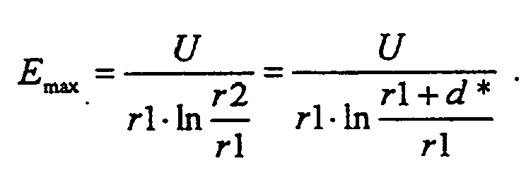
Die Auswirkungen der erhöhten Feldstärke können insbesondere bei elektrischer Dauerbelastung beträchtlich sein, da die Versagensrate t-1 stark überlinear mit dem elektrischen Feld wächst. Es gilt grob ein Potenzgesetz zwischen der Lebenszeit t (in h) und dem elektrischen Feld E (in kV/mm) gemäss
Eine Erniedrigung der Kantenfeldstärke liesse sich nun beispielsweise dadurch erreichen, dass man von einer Isolierung 14 mit konstanter Dicke d1 (= d*), wie sie in Fig. 1 bzw. Fig. 2 gezeigt ist, auf eine Isolierung mit eckiger Aussenkontur (r2= 0) überginge. Wenn man unter dieser Annahme für einen Wert von d1 = 2,5 mm und r1 = 2,5 mm eine auf dem Finite-Elemente-Verfahren basierende Computermodellrechnung durchführt, ergibt sich eine Reduktion der maximalen Feldstärke Emax im Kantenbereich von 11%, was bei einem Lebensdauerexponenten von 8 einer rechnerischen Lebensdauerverlängerung um den Faktor 2,5 entspricht. Dieser Faktor erhöht sich überproportional mit höherem Lebensdauerexponenten (z.B. Faktor 4 bein = 12).A lowering of the edge field strength could now be achieved, for example, by using an
Es ist Aufgabe der Erfindung, einen Wicklungsstab zu schaffen, bei welchem mit einfachen Mitteln eine deutliche Verringerung der Maximalfeldstärke im Kantenbereich erzielt wird, ohne dass die Dicke der Isolation im Bereich der Flachseiten erhöht werden muss, sowie ein Verfahren zu dessen Herstellung anzugeben.It is an object of the invention to provide a winding rod in which a simple reduction of the maximum field strength in the edge region is achieved without the need to increase the thickness of the insulation in the region of the flat sides, and to provide a method for its production.
Die Aufgabe wird bei einem Wicklungsstab der eingangs genannten Art dadurch gelöst, dass die Dicke der Isolierung an den Kanten des Wicklungsstabes grösser ist als die Dicke der Isolierung an den Flachseiten des Wicklungsstabes. Durch die Vergrösserung der Isolierungsdicke im Kantenbereich ergibt sich eine Entzerrung der Feldlinien des elektrischen Feldes, die zu der gewünschten Reduzierung der Kantenfeldstärke führt.The object is achieved with a winding rod of the type mentioned above in that the thickness of the insulation at the edges of the winding rod is greater than the thickness of the insulation on the flat sides of the winding rod. Increasing the insulation thickness in the edge area results in equalization the field lines of the electric field, which leads to the desired reduction of the edge field strength.
Eine erste bevorzugte Ausführungsform des erfindungsgemässen Wicklungsstabes ist dadurch gekennzeichnet, dass die Isolierung an den Kanten des Wicklungsstabes eine Krümmung mit einer inneren Krümmungskontur und einem äusseren Krümmungsradius aufweist, und dass der äussere Krümmungsradius kleiner ist als die Summe aus dem äquivalenten inneren Krümmungsradius der inneren Krümmungskontur und der Dicke der Isolierung an den Flachseiten des Wicklungsstabes. Durch die Beibehaltung eines von Null verschiedenen äusseren Krümmungsradius ergibt sich eine für die Feldverteilung und für die mechanische Stabilität günstige gleichmässige Aenderung der Dicke im Kantenbereich.A first preferred embodiment of the winding rod according to the invention is characterized in that the insulation at the edges of the winding rod has a curvature with an inner curvature contour and an outer curvature radius, and that the outer curvature radius is smaller than the sum of the equivalent inner curvature radius of the inner curvature contour and the thickness of the insulation on the flat sides of the winding bar. By maintaining a non-zero outer radius of curvature results in a favorable for the field distribution and for mechanical stability uniform uniform thickness change in the edge region.
Grundsätzlich lässt sich eine derartige Formung der Kantenbereiche mit einer gewickelten Isolierung erreichen, wenn für die Isolierung thermoplastische Bänder verwendet werden. Besonders einfach wird die Formung jedoch dann, wenn gemäss einer zweiten bevorzugten Ausführungsform die Isolierung aus einem thermoplastischen Polymer besteht, in welchem Füllstoffpartikel aus einem Isolierstoff verteilt sind. In einer bevorzugten Weiterbildung dieser werden als thermoplastisches Polymer Polyetheretherketon (PEEK) und als Füllstoffpartikel Glimmerplättchen verwendet. Anstelle des PEEK können aber mit gutem Erfolg auch andere Stoffe wie z.B. Polysulfon (PSU) oder Polyäthersulfon (PES) verwendet werden.In principle, such a shaping of the edge regions with a wound insulation can be achieved if thermoplastic tapes are used for the insulation. However, the shaping is particularly simple if, according to a second preferred embodiment, the insulation consists of a thermoplastic polymer in which filler particles are distributed from an insulating material. In a preferred development of this, polyetheretherketone (PEEK) and, as filler particles, mica platelets are used as the thermoplastic polymer. But instead of the PEEK, other substances such as e.g. Polysulfone (PSU) or Polyethersulfone (PES) can be used.
Gemäss einer weiteren bevorzugten Ausführungsform der Erfindung wird die zur Reduktion der Kantenfeldstärke eingesetzte spezielle Formgebung der Isolierung im Kantenbereich auch auf die Leiter des von der Isolierung umgebenen Leiterbündels ausgedehnt, dadurch, dass zumindest die im Bereich der Kanten angeordneten Leiter jeweils aus einem Bündel einzelner, isolierter, insbesondere miteinander verseilter, Drähte bestehen. Hierdurch wird es möglich, die Leiter selbst durch Formpressen in eine Form zu bringen, die zu einer weiteren Erhöhung der Isolierungsdicke im Kantenbereich führt. Die Drähte können dabei beispielsweise als Runddrähte ausgebildet sein, aber auch (nach Art von Miniatur- Roebelstäben) vierkantig sein.According to a further preferred embodiment of the invention, the special shaping of the insulation used for the reduction of the edge field strength is also extended to the conductors of the conductor bundle surrounded by the insulation, in that at least the conductors arranged in the region of the edges each consist of a bundle of individual, insulated ones , in particular stranded together, wires. This makes it possible to bring the conductors themselves by molding in a mold, which leads to a further increase in the insulation thickness in the edge region. The wires can for example be formed as round wires, but also (in the manner of miniature Roebelstäben) be square.
In einer bevorzugten Weiterbildung dieser Ausführungsform sind die Bündel aus den Drähten zur Erzielung einer glatten Aussenkontur mit einer halbleitenden Bindemasse imprägniert, und ist in dem Bündel aus Drähten zur Ankopplung an die halbleitende Bindemasse wenigstens ein Draht blank belassen oder blank gemacht. Hierdurch ist es möglich, einen ungünstigen Einfluss der Drahtbündel auf die Feldverteilung zu minimieren. Ueber die Glättung der Aussenkontur eines einzelnen Leiters hinaus kann die Aussenkontur des gesamten Leiterbündels geglättet werden, wenn gemäss einer weiteren Ausführungsform die Leiter des Wicklungsstabes voneinander durch Zwischenräume beabstandet sind, und die Zwischenräume mit einer halbleitenden Ueberbrückungsmasse gefüllt sind, die vorzugsweise (in Stabrichtung) ein zumindest abschnittweise nichtlineares, spannungsbegrenzendes Verhalten aufweist.In a preferred embodiment of this embodiment, the bundles of the wires to achieve a smooth outer contour impregnated with a semiconductive binder, and is in the bundle of wires for coupling to the semiconducting binder at least leave a wire bare or blank. This makes it possible to minimize an unfavorable influence of the wire bundles on the field distribution. In addition to the smoothing of the outer contour of a single conductor, the outer contour of the entire conductor bundle can be smoothed if, according to another embodiment, the conductors of the winding rod are spaced from each other by interspaces, and the interstices are filled with a semiconductive bridging compound, preferably (in bar direction) has at least partially non-linear, voltage-limiting behavior.
Das erfindungsgemässe Verfahren zum Herstellen eines Wicklungsstabes, bei welchem Wicklungsstab die Isolierung im wesentlichen aus einem thermoplastischen Material besteht, ist dadurch gekennzeichnet, dass der Wicklungsstab nach dem Aufbringen der Isolierung einem Kalibrierprozess unterzogen wird, bei welchem dem verformbaren Material der Isolierung eine vorgegebene Randkontur aufgeprägt wird, welche zu einer erhöhten Dicke der Isolierung im Bereich der Kanten führt. Durch die Entkopplung von Auftrags- und Formungsprozess lassen sich die beiden Prozessschritte getrennt optimieren und gleichzeitig kontinuierlich durchführen. Die Isolierung lässt sich dabei in besonders gleichmässigen und gut formbaren Schichten aufbringen, wenn gemäss einer ersten bevorzugten Ausführungsform des erfindungsgemässen Verfahrens die Isolierung durch ein Verfahren aus der Reihe der Pulverbeschichtungsverfahren, insbesondere Sprühsintern oder thermisches Spritzen, und Extrusionsverfahren aufgebracht wird.The method according to the invention for producing a winding rod, in which winding rod the insulation consists essentially of a thermoplastic material, is characterized in that the winding rod is subjected to a calibration process after application of the insulation, in which the deformable material of the insulation a predetermined edge contour is impressed , which leads to an increased thickness of the insulation in the region of the edges. By decoupling the application and molding process, the two process steps can be optimized separately and carried out simultaneously. The insulation can be applied in particularly uniform and readily moldable layers if, according to a first preferred embodiment of the process according to the invention, the insulation is applied by a process from the series of powder coating processes, in particular spray sintering or thermal spraying, and extrusion processes.
Das erfindungsgemässe Verfahren lässt sich besonders schnell und präzise durchführen, wenn gemäss einer weiteren bevorzugten Ausführungsform zum Durchführen des Kalibrierprozesses Kalibrierwalzen, welche parallel zu den Mittelebenen des Wicklungsstabes und in einem festen Abstand davon angeordnet sind, relativ zum Wicklungsstab über dessen Oberflächen bewegt werden., und innerhalb des Kalibrierprozesses mittels zusätzlicher Kantenrollen den Kanten des Wicklungsstabes ein vorgegebener Krümmungsradius aufgeprägt wird.The method according to the invention can be carried out particularly quickly and precisely if, in accordance with a further preferred embodiment, calibration rollers which are arranged parallel to the center planes of the winding rod and at a fixed distance are moved relative to the winding rod over their surfaces for carrying out the calibration process Within the calibration process by means of additional edge rollers the edges of the winding bar a predetermined radius of curvature is impressed.
Weitere Ausführungsformen ergeben sich aus den abhängigen Ansprüchen.Further embodiments emerge from the dependent claims.
Die Erfindung soll nachfolgend anhand von Ausführungsbeispielen im Zusammenhang mit der Zeichnung näher erläutert werden. Es zeigen
- Fig. 1
- im Querschnitt einen in eine Statornut eingelegten Wicklungsstab nach dem Stand der Technik mit einer gewickelten Isolierung mit im wesentlichen konstanter Dicke d1;
- Fig. 2
- einen Ausschnitt im Kantenbereich des Wicklungsstabes nach Fig. 1;
- Fig. 3
- die zu Fig. 1 vergleichbare Darstellung eines ersten Ausführungsbeispiels der Erfindung, bei welchem durch Verringerung des äusseren Krümmungsradius r3 der Isolierung an der Kante die Dicke der Isolierung in diesem Bereich erhöht wird;
- Fig. 4
- eine zu Fig. 2 vergleichbare Darstellung des Kantenausschnitts von Fig. 3;
- Fig. 5
- eine zu Fig. 3 vergleichbare Darstellung eines zweiten Ausführungsbeispiels der Erfindung, bei welchem zur weiteren Erhöhung der Isolierungsdicke im Kantenbereich der angrenzende Leiter stärker abgerundet wird;
- Fig. 6
- eine zu Fig. 4 vergleichbare Darstellung des Kantenausschnitts von Fig. 5;
- Fig. 7
- eine schematisierte Darstellung der beim Kalibrierungsvorgang nach der Erfindung auftretenden Effekte; und
- Fig. 8
- in einer perspektivischen Darstellung ein Ausführungsbeispiel des Kalibrierprozesses nach dem erfindungsgemässen Verfahren.
- Fig. 1
- in cross-section a winding rod inserted in a stator in the prior art with a wound insulation with a substantially constant thickness d1;
- Fig. 2
- a section in the edge region of the winding rod of Fig. 1;
- Fig. 3
- similar to Figure 1 representation of a first embodiment of the invention, in which by reducing the outer radius of curvature r3 of the insulation at the edge, the thickness of the insulation is increased in this area;
- Fig. 4
- a comparable to Figure 2 representation of the edge detail of Fig. 3;
- Fig. 5
- a comparable to Figure 3 representation of a second embodiment of the invention, wherein for further increasing the insulation thickness in the edge region of the adjacent conductor is more rounded.
- Fig. 6
- a comparable to Figure 4 representation of the edge section of Fig. 5.
- Fig. 7
- a schematic representation of the effects occurring during the calibration process according to the invention; and
- Fig. 8
- in a perspective view of an embodiment of the calibration process according to the inventive method.
In den Fig. 3 und 4 ist ein erstes bevorzugtes Ausführungsbeispiel des Wicklungsstabes nach der Erfindung im Querschnitt wiedergegeben. Die Vergrösserung der Dicke der Isolierung 14 des Wicklungsstabes 10 im Bereich der Kanten 15 wird in diesem Fall dadurch erreicht, dass der Krümmungsradius r3 an der Aussenseite der Isolierung 14 kleiner gewählt wird als die Summe aus dem Krümmungsradius r1 auf der Innenseite der Isolierung 14 (bzw. des Leiters 13) und der Dicke d1 der Isolierung auf den Flachseiten der Isolierung (siehe Fig. 3). Dadurch ergibt sich im Vergleich zum herkömmlichen Fall aus Fig. 1 und 2 (in Fig. 4 strichliert eingezeichnet) eine Dicke d2 der Isolierung 14 im Kantenbereich, die grösser ist als die Dicke d1. Für den Extremfall mit r3 = 0 (scharfe Aussenkante der Isolierung 14) ist die Dicke d2 maximal 
Ausgehend vom konventionellen Wickel- und Tränkprozess als Herstellungsverfahren von Isolierungen für die Leiter in rotierenden elektrischen Maschinen sind scharfe Aussenkanten für die Isolierung 14 theoretisch machbar durch eine Deformation der Isolierung im imprägnierten, aber noch nicht ausgehärteten Zustand. Dies setzt eine Fliessfähigkeit der Isolierung voraus. Da jedoch der üblicherweise verwendete Glasträger des Glimmerbandes sehr zugfest ist, wird ein hinreichender Fluss der Isolierung nur dann stattfinden, wenn das Glas/Glimmerband sehr lose um den Leiterstab gewickelt ist (Wickelzug annähernd gleich 0). Eine derartige Isolierung hat jedoch den Nachteil, dass die Bandlagen extrem leicht verrutschen, Falten bilden können und somit eine gleichmässige Bewicklung des Leiterbündels nicht mehr gewährleistet ist. Eine gleichmässige Bewicklung ist aber ein Grundvoraussetzung für eine homogene und funktionsfähige Isolierung.Starting from the conventional winding and impregnation process as a method of manufacturing insulation for the conductors in rotating electrical machines, sharp outer edges for the
Eine hinreichend deformierbare Isolation ist nur dann zu erwarten, wenn ein Herstellungsverfahren für die Isolierung 14 gewählt wird, bei dem kein Glasträger verwendet wird. Diese Voraussetzung erfüllen beispielsweise die Pulverbeschichtungsverfahren Sprühsintern und thermisches Spritzen, Extrusionsverfahren sowie Verfahren, bei denen das Leiterbündel mit thermoplastischen Bändern umwickelt und anschliessend heiss verpresst wird (siehe dazu beispielsweise die Druckschrift EP-A2-0 660 336). Alle genannten Verfahren geben für sich genommen noch nicht notwendigerweise den gewünschten Effekt der Dickenerhöhung an den Kanten; es ist sogar denkbar, dass, wenn keine zusätzlichen Vorkehrungen getroffen werden, die Dicke der Isolierung 14 an den Kanten 15 geringer ausfällt. Für die Formung der Kanten ist daher ein zusätzlicher Bearbeitungsschritt notwendig. Eine weitere notwendige Bedingung ist, dass die verwendete Isoliermasse, vorzugsweise ein Polymer, in einem weiten Temperaturbereich plastisch verformbar ist.A sufficiently deformable insulation is to be expected only if a manufacturing process for the
Die gewünschte zielgerichtete Deformation der Isoliermasse (des Polymers) im Kantenbereich lässt sich dann gemäss Fig. 7 und 8 durch ein sogenanntes Kalibrieren der Isolierung 34 kurz nach dem Aufspritzen (gilt für thermisches Spritzen) bzw. nach dem Sintern (gilt für Sprühsintern) realisieren, indem Kalibrierwalzen bzw. -rollen auf den Flachseiten der Isolierung entsprechend der schematisierten Darstellung in Fig. 7 in definierter Weise über das noch verformbare Isoliermaterial geführt werden. Die auf die Unterlage 26 aufgebrachte Isoliermasse 27, die neben den untergemischten Füllstoffpartikeln 29 (z.B. Glimmerplättchen) auch noch Luftblasen 28 enthält, wird dabei durch die Kalibrierwalze 31, die in definiertem Abstand über die Unterlage 26 gerollt wird, verdichtet und in der Dicke vergleichmässigt.The desired targeted deformation of the insulating material (of the polymer) in the edge region can then be realized according to FIGS. 7 and 8 by a so-called calibration of the
In einer bevorzugten Ausführungsform des Verfahrens wird die Isoliermasse durch sukzessives Auftragen (Aufspritzen) mehrerer dünner Schichten gebildet. Das Kalibrieren wird dann nach jedem Spritzvorgang durchgeführt. Es ergeben sich hierdurch zusätzlich positive Effekte aufgrund dessen, dass die eventuell vorhandene Luftblasen 28 aus der Isolierung herausgedrückt werden, und dass kurzfaserige oder plättchenförmige Füllstoffpartikel 29 in eine eventuell gewünschte, gerichtete Lage parallel zur Oberfläche orientiert werden (rechte Seite Fig. 7).In a preferred embodiment of the method, the insulating compound is formed by successive application (spraying) of several thin layers. Calibration is then performed after each injection. This results in additional positive effects due to the fact that the possibly existing air bubbles 28 are pushed out of the insulation, and that kurzfaserige or platelet-shaped
Ein mechanisches Gemisch aus Polyetheretherketon (PEEK) und Glimmer im Mengenverhältnis 1:1 wird bei Raumtemperatur auf einen Rechteckleiter (mit Leitern 33) mittels elektrostatischem Spritzen (Untervariante des Sprühsinterverfahrens) aufgetragen. Es bleibt allseitig eine Schicht von ca. 0,2 mm Dicke haften. Der Polymeranteil des Pulvers wird durch Erwärmen in einem Umluftofen (380°C, 10 min) verschmolzen. Direkt anschliessend wird (Fig. 8) der Wicklungsstab 32 durch jeweils zwei hintereinanderliegende Walzenpaare (Kalibrierwalzen 35, 36, 37) auf beiden Stirn- und Breitseiten kalibriert. Die Kalibrierwalzen 35, 36, 37 sind dabei parallel zu den Mittelebenen 41, 42 des Wicklungsstabes 32 und in einem festen Abstand davon angeordnet. Um einen zu starken Wärmeentzug und ein dadurch bedingtes verfrühtes Verfestigen des Polymers zu vermeiden, bestehen die Rollen vorzugsweise aus Glasröhren oder einem anderen warmfesten Material mit möglichst geringer Wärmeleitfähigkeit. Die Kalibrierung kann realisiert werden, indem entweder der Wicklungsstab 32 zwischen den feststehenden Kalibrierwalzen 35, 36, 37 hindurchgeführt wird (Pfeilrichtung in Fig. 8), oder vorteilhafter, indem die Walzen über den feststehenden Stab geführt werden (Konzept Roboter oder Wickelmaschine).A mechanical mixture of polyetheretherketone (PEEK) and mica in a ratio of 1: 1 is applied at room temperature to a rectangular conductor (with conductors 33) by means of electrostatic spraying (sub-variant of the spray sintering method). It remains on all sides a layer of about 0.2 mm thickness adhere. The polymer portion of the powder is fused by heating in a convection oven (380 ° C, 10 min). Directly afterwards, the winding
Wie in Beispiel 1, jedoch mit geheizten Kalibrierwalzen 35, 36, 37. Die Walzentemperatur beträgt dabei etwa 330°C.As in Example 1, but with
Ein mechanisches Gemisch aus Polyetheretherketon (PEEK) und Glimmer im Mengenverhältnis 1:1 wird auf einen Rechteckleiter mittels Flammspritzen bis zur gewünschten Enddicke aufgetragen. Der Leiter ist dabei auf etwa 180°C vorgeheizt. Das Kalibrieren erfolgt entsprechend Beispiel 1 und 2.A mechanical mixture of polyetheretherketone (PEEK) and mica in a ratio of 1: 1 is applied to a rectangular conductor by flame spraying to the desired final thickness. The conductor is preheated to about 180 ° C. The calibration is carried out according to example 1 and 2.
Wie Beispiel 3, jedoch wird die Enddicke nicht in einem einzigen Durchgang erreicht, sondern durch wiederholtes Spritzen und Kalibrieren dünner Schichten mit einer Dicke von ca. 0,2 mm. Dieses Vorgehen hat gegenüber Beispiel 3 den Vorteil, dass die Glimmerplättchen sich in der gewünschten Art parallel zur Oberfläche orientieren und der Blasengehalt der Isolierung praktisch auf Null zurückgeht.As in Example 3, but the final thickness is not achieved in a single pass, but by repeated spraying and calibrating thin layers with a thickness of about 0.2 mm. This procedure has the advantage over Example 3 that the mica platelets orient themselves in the desired manner parallel to the surface and that the bubble content of the insulation is practically zero.
Wie Beispiel 4, jedoch werden (Fig. 8) neben den Flachseiten des Wicklungsstabes 32 auch die Kanten 40 mit speziellen Kantenrollen 38, 39 kalibriert, die in Prozessrichtung vorzugsweise hinter den Kalibrierwalzen 35, 36, 37 angeordnet sind. Hierdurch wird ein äusserer Krümmungsradius (r3 in Fig. 4) der Isolierung 34 definiert und es wird erreicht, dass die Glimmerplättchen in dem elektrisch besonders heiklen Kantenbereich in günstiger Weise ausgerichtet sind.As in example 4, however, in addition to the flat sides of the winding
Wie Beispiele 1 bis 5, jedoch wird statt des PEEK/Glimmer-Gemisches ein PEEK/Glimmer-Compound verarbeitet.As Examples 1 to 5, but instead of the PEEK / mica mixture, a PEEK / mica compound is processed.
Um einen Rechteckleiter werden Bänder, bestehend aus Polysulphon (PSU)- gefüllt mit 30 Masse-% Glimmer - gewickelt. Die Anzahl Lagen an aufgewickelten Bändern ist 5-10% grösser als es der gewünschten Isolierungsdicke entspricht. Nach dem Bewickeln erfolgt die Kalibrierung entsprechend Beispiel 2 mit geheizten Walzen. Die Walzentemperatur beträgt dabei 250°C.Around a rectangular conductor, bands consisting of polysulphone (PSU) filled with 30% by mass of mica are wound. The number of layers of wound tapes is 5-10% greater than the desired insulation thickness. After winding, the calibration is carried out according to Example 2 with heated rollers. The roller temperature is 250 ° C.
Ein weiteres bevorzugtes Ausführungsbeispiel für einen Wicklungsstab nach der Erfindung ist in den Fig. 5 und 6 wiedergegeben. Der Wicklungsstab 16, der in die Nut 17 eines Statorpakets 18 eingelegt ist, umfasst eine Mehrzahl von Leitern 19, 20, 21, die von einer Isolierung 22 umgeben sind. Zumindest die äusseren Leiter 19, 21, vorzugsweise auch die anderen Leiter 20, bestehen in diesem Fall aus verseilten, isolierten Drähten 25. Die äusseren Leiter 19, 21 werden nach den Prinzipien der Feldtheorie (Rogowski-Profile) abgerundet (Krümmungsradius r5). Die Abrundung der Leiter 19, 21 wird durch die Strukturierung in die Drähte 25 einfach gemacht. Durch die Abrundung der Leiter 19, 21 ergibt sich gegenüber der Dicke d3 an den Flachseiten (Fig. 5) eine erhöhte Dicke d4 im Bereich der Kanten 23 (Fig. 6), die dadurch noch vergrössert werden kann, dass der Krümmungsradius r4 an der äusseren Kante der Isolierung 22 verkleinert wird.Another preferred embodiment of a winding rod according to the invention is shown in Figs. 5 and 6 reproduced. The winding
Die (minimale) Dicke d5 zur Schmalseite des Wicklungsstabes 16 hin lässt sich dabei nach den folgenden Formeln bestimmen:


Durch Einsetzen der Gleichungen ineinander und Auflösen nach d5 kann dann beispielsweise die Dicke d5 in Abhängigkeit von d3 berechnet werden. Die kreisförmige Ausgestaltung ist beispielhaft angegeben. Eine noch weitergehende Optimierung hinsichtlich der Feldstärke kann durch Verwendung von nicht exakt kreisförmigen Krümmungskonturen der Leiter 19, 21 gefunden werden.By substituting the equations into one another and solving for d5, it is then possible, for example, to calculate the thickness d5 as a function of d3. The circular configuration is given by way of example. An even further optimization in terms of field strength can be found by using not exactly circular curvature contours of the
Um eine hinsichtlich der elektrischen Feldstärke günstigere glatte Aussenkontur des Leiterbündels 19, 20, 21 in der Isolierung 22 zu erzielen, können die Zwischenräume 24 zwischen den Leitern 19, 20, 21 mit einer halbleitenden Ueberbrückungsmasse ausgefüllt sein. Ein vergleichbarer Effekt ergibt sich, wenn der "grüne" Stab, d.h. das Leiterbündel vor der Einbettung in die Isolierung 22, mit einem halbleitenden Anstrich versehen wird. Besteht die halbleitende Ueberbrückungsmasse bzw. der halbleitende Anstrich aus einem Material, welches ein elektrisch nichtlineares Verhalten aufweist, können zusätzlich Spannungsstosswellen zwischen den Leitern 19, 20, 21 linear verteilt werden.In order to achieve a more favorable in terms of electric field strength smooth outer contour of the
Eine weitere Verbesserung ergibt sich, wenn die Drähte 25, aus denen die Leiter 19, 20, 21 bestehen, nach dem Verseilen in einer Presse komprimiert werden, um den Cu-Anteil im Leiter möglichst gross zu halten. Insbesondere ist es vom elektrischen Verhalten her günstig, wenn die aus den Drähten 25 bestehenden Leiter in eine Form gepresst und mit einer halbleitenden Bindemasse imprägniert werden. Auch hierdurch wird eine für die maximale Feldstärke wichtige glatte Aussenkontur erreicht. Die Ankopplung an die halbleitende Bindemasse wird dabei vorzugsweise dadurch bewirkt, dass wenigstens ein Runddraht blank belassen wird.A further improvement results when the
- 10,1610.16
- Wicklungsstabwinding bar
- 11,1711.17
- Nutgroove
- 12,1812.18
- Statorpaketstator
- 1313
- Leiterladder
- 14,2214.22
- Isolierunginsulation
- 15,2315.23
- Kanteedge
- 19,20,2119,20,21
- Leiterladder
- 2424
- Zwischenraumgap
- 2525
- Runddrahtround wire
- 2626
- Unterlagedocument
- 2727
- Isoliermasseinsulating compound
- 2828
- Luftblasebubble
- 2929
- Füllstoffpartikelfiller
- 3030
- Oberflächesurface
- 3131
- Kalibrierwalzecalibrating
- 3232
- Wicklungsstabwinding bar
- 3333
- Leiterladder
- 3434
- Isolierunginsulation
- 35,36,3735,36,37
- Kalibrierwalzecalibrating
- 38,3938.39
- Kantenrolleedge roller
- 4040
- Kanteedge
- 41,4241.42
- Mittelebenemidplane
- r1,..,r5r1, .., r5
- Krümmungsradiusradius of curvature
- d*,d1,..,d5d *, d1, .., d5
- Dicke (Isolierung)Thickness (insulation)
Claims (21)
- Winding bar (10,16,32) for the high-voltage winding, in particular stator winding, of an electric machine, comprising a plurality of conductors (13;19,...,21;33) which are arranged above and/or next to one another, and a conductor bundle with a rectangular cross section, the conductor bundle being surrounded outside on all sides by an insulation (14,22,34), characterized in that the thickness (d2,d4) of the insulation (14,22,34) on the edges (15,23,40) of the winding bar (10,16,32) is greater than the thickness (d1,d3) of the insulation (14,22,34) on the flat sides of the winding bar (10,16,32).
- Winding bar according to Claim 1, characterized in that the insulation (14,22,34) on the edges (15,23,40) of the winding bar (10,16,32) has a curvature with an inner curvature contour (r1,r5) and an outer radius of curvature (r3,r4) and characterized in that the outer radius of curvature (r3,r4) is smaller than the sum of the equivalent inner radius of curvature (r1,r5) of the inner curvature contour and the thickness (d1,d3) of the insulation (14,22,34) on the flat sides of the winding bar (10,16,32).
- Winding bar according to Claim 2, characterized in that the inner curvature contour (r1,r5) is circular.
- Winding bar according to Claim 2, characterized in that the inner curvature contour is field-optimized.
- Winding bar according to one of Claims 1 to 4, characterized in that the insulation (14,22,34) consists of a thermoplastic polymer in which filler particles (29) made from an insulant are distributed.
- Winding bar according to Claim 5, characterized in that polyetherether ketone (PEEK) is used as the thermoplastic polymer, and mica platelets are used as the filler particles (29).
- Winding bar according to one of Claims 1 to 6, characterized in that at least the conductors (19,21) arranged in the region of the edges (23) respectively comprise a bundle of individual insulated, in particular stranded wires (25).
- Winding bar according to Claim 7, characterized in that for the purpose of achieving a smooth outer contour the bundles of the wires (25) are impregnated with a semiconducting binding compound.
- Winding bar according to one of Claims 1 to 8, characterized in that the conductors (13;19,...,21;33) of the winding bar (10,16,32) are spaced apart from one another by interspaces (24) and in that for the purpose of achieving a smooth outer contour the interspaces (24) are filled with a semiconducting bridging compound.
- Winding bar according to Claim 8, characterized in that for the purpose of coupling to the semiconducting binding compound at least one wire (25) in the bundle of wires (25) is left or made bare.
- Winding bar according to Claim 9, characterized in that in the bar direction the semiconducting bridging compound exhibits a voltage-limiting behavior which is nonlinear, at least in sections.
- Method for producing a winding bar as claimed in Claim 1, in the case of which winding bar (10,16,32) the insulation (14,22,34) consists essentially of a thermoplastic material, characterized in that after the application of the insulation (14,22,34) the winding bar (10,16,32) is subjected to a calibration process in which there is impressed on the deformable material of the insulation (14,22,34) a prescribed edge contour which leads to an increased thickness (d2,d4) of the insulation (14,22,34) in the region of the edges (40).
- Method according to Claim 12, characterized in that the insulation (14,22,34) is applied by means of a method from the range of the powder-coating methods, in particular spray sintering or thermal spraying, and extrusion methods.
- Method according to Claim 13, characterized in that the insulation (14,22,34) is applied sequentially in a plurality of layers, in particular thin layers of less than 1 mm, preferably approximately of 0.2 mm, thickness.
- Method according to Claim 14, characterized in that the calibration process is carried out after the application of each individual layer.
- Method according to one of Claims 12 to 15, characterized in that for the purpose of carrying out the calibration process calibration rolls (35,36,37) which are arranged parallel to the middle planes (41,42) of the winding bar (10,16,32) and at a fixed spacing therefrom are moved relative to the winding bar (10,16,32) over the surfaces (30) thereof.
- Method according to Claim 16, characterized in that within the calibration process a prescribed radius of curvature (r3,r4) is impressed on the edges (15,23,40) of the winding bar (10,16,32) by means of additional edge rollers (38,39).
- Method according to Claim 17, characterized in that the edge rollers (r3,r4) are arranged downstream of the calibration rolls (35,36,37) in the process direction.
- Method according to one of Claims 12 to 18, characterized in that the insulation (14,22,34) is applied at raised temperatures, and the calibration process is carried out as long as the applied insulation (14,22,34) is still at raised temperatures.
- Method according to Claim 19, characterized in that use is made of calibration rolls (35,36,37) or calibration rollers (38,39) which consist of a material with a low thermal conductivity, in particular of glass.
- Method according to Claim 19, characterized in that use is made of calibration rolls (35,36,37) or calibration rollers (38,39) which are heated to raised temperatures during the calibration process.
Applications Claiming Priority (2)
| Application Number | Priority Date | Filing Date | Title |
|---|---|---|---|
| DE19817287A DE19817287A1 (en) | 1998-04-18 | 1998-04-18 | Winding rod for the high-voltage winding of an electrical machine and method for producing such a winding rod |
| DE19817287 | 1998-04-18 |
Publications (3)
| Publication Number | Publication Date |
|---|---|
| EP0951132A2 EP0951132A2 (en) | 1999-10-20 |
| EP0951132A3 EP0951132A3 (en) | 2002-01-09 |
| EP0951132B1 true EP0951132B1 (en) | 2007-05-02 |
Family
ID=7864990
Family Applications (1)
| Application Number | Title | Priority Date | Filing Date |
|---|---|---|---|
| EP99810257A Expired - Lifetime EP0951132B1 (en) | 1998-04-18 | 1999-03-23 | Winding bar for high voltage electric electric machines and method for manufacturing such a winding bar |
Country Status (6)
| Country | Link |
|---|---|
| US (1) | US6404092B1 (en) |
| EP (1) | EP0951132B1 (en) |
| JP (1) | JP3955696B2 (en) |
| CN (1) | CN1233101A (en) |
| AT (1) | ATE361577T1 (en) |
| DE (2) | DE19817287A1 (en) |
Families Citing this family (35)
| Publication number | Priority date | Publication date | Assignee | Title |
|---|---|---|---|---|
| GB9907527D0 (en) * | 1999-04-01 | 1999-05-26 | Alstom Uk Ltd | Improvements in electrical machines |
| DE19963378A1 (en) * | 1999-12-28 | 2001-07-12 | Alstom Power Schweiz Ag Baden | Process for producing insulation of electrical conductors using powder coating |
| CN100511924C (en) | 2001-01-09 | 2009-07-08 | 布莱克-德克尔公司 | Electric motor having armature coated with thermally conductive plastic |
| US7814641B2 (en) | 2001-01-09 | 2010-10-19 | Black & Decker Inc. | Method of forming a power tool |
| US7096566B2 (en) * | 2001-01-09 | 2006-08-29 | Black & Decker Inc. | Method for making an encapsulated coil structure |
| US6946758B2 (en) | 2001-01-09 | 2005-09-20 | Black & Decker Inc. | Dynamoelectric machine having encapsulated coil structure with one or more of phase change additives, insert molded features and insulated pinion |
| DE10113299A1 (en) * | 2001-03-16 | 2002-09-19 | Alstom Switzerland Ltd | Manufacturing conducting rods involves cutting continuous wire into sub-conductor lengths, bending sub-conductors, applying electrical insulation, assembling to make conducting rod, etc. |
| US6674203B2 (en) * | 2001-04-24 | 2004-01-06 | Denso Corporation | Vehicle rotary electric machine |
| JP3676707B2 (en) * | 2001-07-18 | 2005-07-27 | 三菱電機株式会社 | Stator for vehicle alternator and manufacturing method thereof |
| US6663816B2 (en) * | 2002-01-31 | 2003-12-16 | General Electric Company | Method of making a dynamoelectric machine conductor bar and method of making a conductor bar dynamoelectric machine |
| DE10260315A1 (en) * | 2002-12-20 | 2004-07-08 | Siemens Ag | Extruded elastic insulation for conductors of electrical machines |
| US6965183B2 (en) * | 2003-05-27 | 2005-11-15 | Pratt & Whitney Canada Corp. | Architecture for electric machine |
| US20050077075A1 (en) * | 2003-10-09 | 2005-04-14 | Yu Wang | Flexible stator bars |
| JP2007295697A (en) * | 2006-04-24 | 2007-11-08 | Toyota Motor Corp | Rotating electrical machine stators and parts used for stators |
| JP2007336725A (en) * | 2006-06-16 | 2007-12-27 | Denso Corp | Rotating electric machine stator |
| CH699023B1 (en) | 2007-01-18 | 2010-01-15 | Alstom Technology Ltd | Conductor bar for the stator of a generator as well as methods for its production. |
| EP1950866A1 (en) | 2007-01-25 | 2008-07-30 | ALSTOM Technology Ltd | Method for manufacturing a conductor bar of a rotating electrical machine and a conductor bar manufactured according to this method |
| US20090058221A1 (en) * | 2007-08-29 | 2009-03-05 | Schlumberger Technology Corporation | System and method for protecting submersible motor winding |
| JP5040739B2 (en) * | 2008-03-10 | 2012-10-03 | トヨタ自動車株式会社 | Split stator member, split stator member manufacturing method, and stator |
| FR2944393B1 (en) * | 2009-04-09 | 2014-10-17 | Converteam Technology Ltd | COIL FOR A ROTATING ELECTRIC MACHINE |
| NL2004752A (en) * | 2009-06-19 | 2010-12-20 | Asml Netherlands Bv | Coil, positioning device, actuator, and lithographic apparatus. |
| US10937564B2 (en) * | 2009-10-26 | 2021-03-02 | Goto Denshi Co., Ltd. | Electric wire for high frequency, high voltage and large current |
| JP5421064B2 (en) * | 2009-10-26 | 2014-02-19 | 後藤電子 株式会社 | High frequency high voltage high current wire |
| EP2348615A1 (en) * | 2010-01-22 | 2011-07-27 | Alstom Technology Ltd | Conductive bar for electric machines |
| EP2403113A1 (en) | 2010-07-02 | 2012-01-04 | Alstom Technology Ltd | Stator Bar |
| US20150028701A1 (en) * | 2010-07-02 | 2015-01-29 | Alstom Technology Ltd | Stator bar |
| EP2696474A4 (en) * | 2011-04-05 | 2016-03-09 | Toyota Motor Co Ltd | STATOR, STATOR MANUFACTURING METHOD, AND FLAT DRIVER FOR WINDING |
| JP5939088B2 (en) * | 2012-08-30 | 2016-06-22 | 株式会社デンソー | Rotating electric machine |
| CN103029034A (en) * | 2012-12-07 | 2013-04-10 | 保定天威集团有限公司 | Electromagnetic wire die R angle processing method and dedicated R angle former |
| EP3608923B1 (en) * | 2018-08-10 | 2021-04-14 | ABB Schweiz AG | Apparatus and method for applying an insulation material onto a conductor |
| CN112937503A (en) * | 2021-04-01 | 2021-06-11 | 河源市凯中精密制造技术有限公司 | Flat steel strip structure with extrusion coating layer and application thereof |
| JP7801931B2 (en) * | 2022-03-30 | 2026-01-19 | 三菱重工業株式会社 | Coil wire, coil wire manufacturing method, stator, and electric motor |
| US20250364858A1 (en) * | 2022-05-20 | 2025-11-27 | Petroliam Nasional Berhad (Petronas) | An electric machine and method of use |
| US12683439B2 (en) * | 2023-10-09 | 2026-07-14 | GM Global Technology Operations LLC | Mixed bar and wire conductor combinations for stators of high-speed electric motors |
| CN117613521B (en) * | 2024-01-18 | 2024-04-02 | 深圳市欧米加智能科技有限公司 | Battery ink-jet printing equipment and printing method thereof |
Family Cites Families (23)
| Publication number | Priority date | Publication date | Assignee | Title |
|---|---|---|---|---|
| US2570786A (en) * | 1948-05-29 | 1951-10-09 | Gen Electric | Method of making dynamoelectric machine windings |
| CH321278A (en) * | 1953-05-07 | 1957-04-30 | Siemens Ag | Groove conductor composed of individual conductors with insulating sleeve for electrical machines and process for its production |
| US2975088A (en) * | 1956-02-29 | 1961-03-14 | Allis Chalmers Mfg Co | Unsupported silicone rubber electrical insulation and method of preparing same |
| JPS423327B1 (en) * | 1963-04-01 | 1967-02-13 | ||
| CH500622A (en) * | 1968-12-10 | 1970-12-15 | Emile Haefely Sa Ets | Device for the continuous wrapping of a bundle of conductors for an electric machine |
| CH551100A (en) * | 1972-09-07 | 1974-06-28 | Bbc Brown Boveri & Cie | PROCESS FOR INSULATING THE WINDING CONDUCTORS OF ROTATING HIGH VOLTAGE MACHINES. |
| NO752943L (en) * | 1974-10-29 | 1976-04-30 | Westinghouse Electric Corp | |
| CH579844A5 (en) * | 1974-12-04 | 1976-09-15 | Bbc Brown Boveri & Cie | |
| JPS6087374A (en) | 1983-10-19 | 1985-05-17 | Canon Inc | Image forming method |
| JPS6134272A (en) | 1984-07-24 | 1986-02-18 | 株式会社 サンワ福岡 | Joint matching machine |
| US5066881A (en) * | 1984-08-23 | 1991-11-19 | General Electric Company | Semi-conducting layer for insulated electrical conductors |
| JPS61247247A (en) * | 1985-04-25 | 1986-11-04 | Toshiba Corp | Winding for rotary electric machine |
| JPS6238043A (en) | 1985-08-12 | 1987-02-19 | Nec Corp | Reflecting mirror for laser communication |
| JPS62193103A (en) * | 1986-02-19 | 1987-08-25 | Fuji Electric Co Ltd | Insulated coil |
| JPS63206134A (en) * | 1987-02-23 | 1988-08-25 | Toshiba Corp | Winding of rotary electric machine |
| US4818909A (en) * | 1988-01-15 | 1989-04-04 | General Electric Company | Insulated coil assembly |
| US4833354A (en) * | 1988-06-13 | 1989-05-23 | Trw Inc. | Oil-filled submergible electric pump motor with unvarnished stator structure |
| JPH03245748A (en) | 1990-02-23 | 1991-11-01 | Toshiba Corp | Air gap armature winding |
| JP3245748B2 (en) | 1992-03-09 | 2002-01-15 | 久光製薬株式会社 | P-menthane derivative and cooling sensate containing the same |
| JPH05319952A (en) * | 1992-05-14 | 1993-12-03 | Sk Kaken Co Ltd | Communicating porous body |
| DE4218927A1 (en) * | 1992-06-10 | 1993-12-16 | Asea Brown Boveri | High voltage insulation for stator windings of electrical machines |
| US5806169A (en) * | 1995-04-03 | 1998-09-15 | Trago; Bradley A. | Method of fabricating an injected molded motor assembly |
| DE19543122A1 (en) * | 1995-11-18 | 1997-05-22 | Asea Brown Boveri | Ladder staff |
-
1998
- 1998-04-18 DE DE19817287A patent/DE19817287A1/en not_active Withdrawn
-
1999
- 1999-03-23 EP EP99810257A patent/EP0951132B1/en not_active Expired - Lifetime
- 1999-03-23 AT AT99810257T patent/ATE361577T1/en not_active IP Right Cessation
- 1999-03-23 DE DE59914317T patent/DE59914317D1/en not_active Expired - Lifetime
- 1999-04-13 US US09/290,180 patent/US6404092B1/en not_active Expired - Fee Related
- 1999-04-16 JP JP10975499A patent/JP3955696B2/en not_active Expired - Fee Related
- 1999-04-19 CN CN99105129A patent/CN1233101A/en active Pending
Non-Patent Citations (1)
| Title |
|---|
| None * |
Also Published As
| Publication number | Publication date |
|---|---|
| DE59914317D1 (en) | 2007-06-14 |
| ATE361577T1 (en) | 2007-05-15 |
| CN1233101A (en) | 1999-10-27 |
| EP0951132A3 (en) | 2002-01-09 |
| JPH11332154A (en) | 1999-11-30 |
| US6404092B1 (en) | 2002-06-11 |
| DE19817287A1 (en) | 1999-10-21 |
| JP3955696B2 (en) | 2007-08-08 |
| EP0951132A2 (en) | 1999-10-20 |
Similar Documents
| Publication | Publication Date | Title |
|---|---|---|
| EP0951132A2 (en) | Winding bar for high voltage electric electric machines and method for manufacturing such a winding bar | |
| DE60107587T2 (en) | INSULATION ARRANGEMENT WITH DISTRIBUTED ELECTRICAL FIELD FOR DYNAMOELECTRIC MACHINE | |
| EP1153726B1 (en) | Insulation of stator windings by injection moulding | |
| DE2436413A1 (en) | HIGH VOLTAGE CABLE | |
| AT521301B1 (en) | Stator with insulation layer | |
| DE69215420T2 (en) | Electrical power cable and method for its manufacture | |
| DE1489900A1 (en) | Kitchen sink | |
| DE1028217B (en) | Process for the production and installation of insulated coils for electrical machines | |
| DE19543122A1 (en) | Ladder staff | |
| DE102018123950A1 (en) | Insulated wire, coil and method of making the coil | |
| DE10023207A1 (en) | Coil insulation | |
| EP1060485B1 (en) | Multiple parallel conductor for electrical machines and devices | |
| EP2740197B1 (en) | Electrical conduction device, overhang corona shielding arrangement and method for producing an overhang corona shielding | |
| DE2931725C2 (en) | Process for the production of self-supporting armature coils for direct current machines | |
| DE3108161C2 (en) | Winding for a transformer or a choke | |
| DE2706719A1 (en) | METHOD OF MANUFACTURING AN ORTHOCYCLIC COIL | |
| EP1371124B1 (en) | Method for producing a bar-type conductor | |
| DE10157591A1 (en) | Winding for a transformer or a coil | |
| DE2516998A1 (en) | DEVICE TO PREVENT CREEPING DISCHARGES | |
| DE3106850C2 (en) | Condenser bushing | |
| EP2885856B1 (en) | Process for manufacturing conductor insulation | |
| DE102022116518A1 (en) | Internally cooled electrical machine with a waveguide winding and method for producing the same | |
| EP0839402B1 (en) | Winding element for an electrical machine | |
| DE1164562B (en) | Corona protection arrangement for the conductor bars lying in the grooves of an iron body of electrical machines operated with high voltage | |
| EP2897256A1 (en) | Insulation system, stator, electric machine, in particular turbo generator, and method for insulating an electrical guide element |
Legal Events
| Date | Code | Title | Description |
|---|---|---|---|
| PUAI | Public reference made under article 153(3) epc to a published international application that has entered the european phase |
Free format text: ORIGINAL CODE: 0009012 |
|
| AK | Designated contracting states |
Kind code of ref document: A2 Designated state(s): AT BE CH CY DE DK ES FI FR GB GR IE IT LI LU MC NL PT SE Kind code of ref document: A2 Designated state(s): AT DE FR GB IT |
|
| AX | Request for extension of the european patent |
Free format text: AL;LT;LV;MK;RO;SI |
|
| PUAL | Search report despatched |
Free format text: ORIGINAL CODE: 0009013 |
|
| RAP1 | Party data changed (applicant data changed or rights of an application transferred) |
Owner name: ALSTOM |
|
| AK | Designated contracting states |
Kind code of ref document: A3 Designated state(s): AT BE CH CY DE DK ES FI FR GB GR IE IT LI LU MC NL PT SE |
|
| AX | Request for extension of the european patent |
Free format text: AL;LT;LV;MK;RO;SI |
|
| 17P | Request for examination filed |
Effective date: 20020524 |
|
| AKX | Designation fees paid |
Free format text: AT DE FR GB IT |
|
| RAP1 | Party data changed (applicant data changed or rights of an application transferred) |
Owner name: ALSTOM (SWITZERLAND) LTD |
|
| RAP1 | Party data changed (applicant data changed or rights of an application transferred) |
Owner name: ALSTOM TECHNOLOGY LTD |
|
| GRAP | Despatch of communication of intention to grant a patent |
Free format text: ORIGINAL CODE: EPIDOSNIGR1 |
|
| GRAS | Grant fee paid |
Free format text: ORIGINAL CODE: EPIDOSNIGR3 |
|
| GRAA | (expected) grant |
Free format text: ORIGINAL CODE: 0009210 |
|
| AK | Designated contracting states |
Kind code of ref document: B1 Designated state(s): AT DE FR GB IT |
|
| REG | Reference to a national code |
Ref country code: GB Ref legal event code: FG4D Free format text: NOT ENGLISH |
|
| REF | Corresponds to: |
Ref document number: 59914317 Country of ref document: DE Date of ref document: 20070614 Kind code of ref document: P |
|
| GBT | Gb: translation of ep patent filed (gb section 77(6)(a)/1977) |
Effective date: 20070604 |
|
| ET | Fr: translation filed | ||
| PLBE | No opposition filed within time limit |
Free format text: ORIGINAL CODE: 0009261 |
|
| STAA | Information on the status of an ep patent application or granted ep patent |
Free format text: STATUS: NO OPPOSITION FILED WITHIN TIME LIMIT |
|
| 26N | No opposition filed |
Effective date: 20080205 |
|
| PGFP | Annual fee paid to national office [announced via postgrant information from national office to epo] |
Ref country code: IT Payment date: 20100322 Year of fee payment: 12 Ref country code: FR Payment date: 20100318 Year of fee payment: 12 |
|
| PGFP | Annual fee paid to national office [announced via postgrant information from national office to epo] |
Ref country code: GB Payment date: 20100208 Year of fee payment: 12 Ref country code: AT Payment date: 20100208 Year of fee payment: 12 |
|
| PGFP | Annual fee paid to national office [announced via postgrant information from national office to epo] |
Ref country code: DE Payment date: 20100331 Year of fee payment: 12 |
|
| GBPC | Gb: european patent ceased through non-payment of renewal fee |
Effective date: 20110323 |
|
| PG25 | Lapsed in a contracting state [announced via postgrant information from national office to epo] |
Ref country code: AT Free format text: LAPSE BECAUSE OF NON-PAYMENT OF DUE FEES Effective date: 20110323 |
|
| REG | Reference to a national code |
Ref country code: FR Ref legal event code: ST Effective date: 20111130 |
|
| PG25 | Lapsed in a contracting state [announced via postgrant information from national office to epo] |
Ref country code: FR Free format text: LAPSE BECAUSE OF NON-PAYMENT OF DUE FEES Effective date: 20110331 Ref country code: DE Free format text: LAPSE BECAUSE OF NON-PAYMENT OF DUE FEES Effective date: 20111001 |
|
| REG | Reference to a national code |
Ref country code: DE Ref legal event code: R119 Ref document number: 59914317 Country of ref document: DE Effective date: 20111001 |
|
| PG25 | Lapsed in a contracting state [announced via postgrant information from national office to epo] |
Ref country code: IT Free format text: LAPSE BECAUSE OF NON-PAYMENT OF DUE FEES Effective date: 20110323 Ref country code: GB Free format text: LAPSE BECAUSE OF NON-PAYMENT OF DUE FEES Effective date: 20110323 |