EP0951260B1 - Procede et dispositif de faconnage de surfaces - Google Patents
Procede et dispositif de faconnage de surfaces Download PDFInfo
- Publication number
- EP0951260B1 EP0951260B1 EP97945865A EP97945865A EP0951260B1 EP 0951260 B1 EP0951260 B1 EP 0951260B1 EP 97945865 A EP97945865 A EP 97945865A EP 97945865 A EP97945865 A EP 97945865A EP 0951260 B1 EP0951260 B1 EP 0951260B1
- Authority
- EP
- European Patent Office
- Prior art keywords
- laser
- unit
- sequence
- individual
- generator
- Prior art date
- Legal status (The legal status is an assumption and is not a legal conclusion. Google has not performed a legal analysis and makes no representation as to the accuracy of the status listed.)
- Expired - Lifetime
Links
- 238000007493 shaping process Methods 0.000 title claims abstract description 22
- 238000000034 method Methods 0.000 title abstract description 24
- 230000008569 process Effects 0.000 title abstract description 9
- 238000012937 correction Methods 0.000 claims abstract description 31
- 238000002679 ablation Methods 0.000 claims abstract description 21
- 230000036961 partial effect Effects 0.000 claims abstract description 16
- 239000002344 surface layer Substances 0.000 claims abstract description 3
- 238000011282 treatment Methods 0.000 claims description 12
- 238000009826 distribution Methods 0.000 claims description 7
- 230000000694 effects Effects 0.000 claims description 6
- 238000012544 monitoring process Methods 0.000 claims description 4
- 238000000608 laser ablation Methods 0.000 claims description 3
- 238000001208 nuclear magnetic resonance pulse sequence Methods 0.000 claims description 3
- 230000033001 locomotion Effects 0.000 claims description 2
- 230000015572 biosynthetic process Effects 0.000 claims 6
- 230000002596 correlated effect Effects 0.000 claims 1
- 238000003754 machining Methods 0.000 abstract description 7
- 238000012545 processing Methods 0.000 description 23
- 239000010410 layer Substances 0.000 description 15
- 208000001491 myopia Diseases 0.000 description 12
- 230000004379 myopia Effects 0.000 description 10
- 210000004087 cornea Anatomy 0.000 description 9
- 238000004364 calculation method Methods 0.000 description 6
- 230000003287 optical effect Effects 0.000 description 4
- 238000013021 overheating Methods 0.000 description 4
- 238000001356 surgical procedure Methods 0.000 description 4
- 230000006866 deterioration Effects 0.000 description 3
- 230000004438 eyesight Effects 0.000 description 3
- 230000004305 hyperopia Effects 0.000 description 3
- 201000006318 hyperopia Diseases 0.000 description 3
- 229910052691 Erbium Inorganic materials 0.000 description 2
- 206010020675 Hypermetropia Diseases 0.000 description 2
- 208000029091 Refraction disease Diseases 0.000 description 2
- 230000004430 ametropia Effects 0.000 description 2
- 239000012620 biological material Substances 0.000 description 2
- 230000007547 defect Effects 0.000 description 2
- 238000010586 diagram Methods 0.000 description 2
- UYAHIZSMUZPPFV-UHFFFAOYSA-N erbium Chemical compound [Er] UYAHIZSMUZPPFV-UHFFFAOYSA-N 0.000 description 2
- 239000011521 glass Substances 0.000 description 2
- 230000005855 radiation Effects 0.000 description 2
- 230000002829 reductive effect Effects 0.000 description 2
- 208000014733 refractive error Diseases 0.000 description 2
- 230000000007 visual effect Effects 0.000 description 2
- 208000032544 Cicatrix Diseases 0.000 description 1
- 208000028006 Corneal injury Diseases 0.000 description 1
- 206010052428 Wound Diseases 0.000 description 1
- 208000027418 Wounds and injury Diseases 0.000 description 1
- 201000009310 astigmatism Diseases 0.000 description 1
- 230000008901 benefit Effects 0.000 description 1
- 230000003247 decreasing effect Effects 0.000 description 1
- 230000023753 dehiscence Effects 0.000 description 1
- 230000018044 dehydration Effects 0.000 description 1
- 238000006297 dehydration reaction Methods 0.000 description 1
- 238000011161 development Methods 0.000 description 1
- 230000018109 developmental process Effects 0.000 description 1
- 230000003628 erosive effect Effects 0.000 description 1
- 238000010304 firing Methods 0.000 description 1
- 230000006872 improvement Effects 0.000 description 1
- 230000003993 interaction Effects 0.000 description 1
- 230000001788 irregular Effects 0.000 description 1
- 239000000463 material Substances 0.000 description 1
- 238000011369 optimal treatment Methods 0.000 description 1
- 230000002093 peripheral effect Effects 0.000 description 1
- 231100000241 scar Toxicity 0.000 description 1
- 230000037387 scars Effects 0.000 description 1
- 238000004904 shortening Methods 0.000 description 1
- 238000005728 strengthening Methods 0.000 description 1
- 230000007704 transition Effects 0.000 description 1
- 238000010792 warming Methods 0.000 description 1
- 230000003313 weakening effect Effects 0.000 description 1
- 230000029663 wound healing Effects 0.000 description 1
Images


Classifications
-
- A—HUMAN NECESSITIES
- A61—MEDICAL OR VETERINARY SCIENCE; HYGIENE
- A61F—FILTERS IMPLANTABLE INTO BLOOD VESSELS; PROSTHESES; DEVICES PROVIDING PATENCY TO, OR PREVENTING COLLAPSING OF, TUBULAR STRUCTURES OF THE BODY, e.g. STENTS; ORTHOPAEDIC, NURSING OR CONTRACEPTIVE DEVICES; FOMENTATION; TREATMENT OR PROTECTION OF EYES OR EARS; BANDAGES, DRESSINGS OR ABSORBENT PADS; FIRST-AID KITS
- A61F9/00—Methods or devices for treatment of the eyes; Devices for putting in contact-lenses; Devices to correct squinting; Apparatus to guide the blind; Protective devices for the eyes, carried on the body or in the hand
- A61F9/007—Methods or devices for eye surgery
- A61F9/008—Methods or devices for eye surgery using laser
- A61F9/00802—Methods or devices for eye surgery using laser for photoablation
- A61F9/00804—Refractive treatments
-
- B—PERFORMING OPERATIONS; TRANSPORTING
- B23—MACHINE TOOLS; METAL-WORKING NOT OTHERWISE PROVIDED FOR
- B23K—SOLDERING OR UNSOLDERING; WELDING; CLADDING OR PLATING BY SOLDERING OR WELDING; CUTTING BY APPLYING HEAT LOCALLY, e.g. FLAME CUTTING; WORKING BY LASER BEAM
- B23K26/00—Working by laser beam, e.g. welding, cutting or boring
- B23K26/02—Positioning or observing the workpiece, e.g. with respect to the point of impact; Aligning, aiming or focusing the laser beam
- B23K26/06—Shaping the laser beam, e.g. by masks or multi-focusing
- B23K26/062—Shaping the laser beam, e.g. by masks or multi-focusing by direct control of the laser beam
- B23K26/0622—Shaping the laser beam, e.g. by masks or multi-focusing by direct control of the laser beam by shaping pulses
-
- A—HUMAN NECESSITIES
- A61—MEDICAL OR VETERINARY SCIENCE; HYGIENE
- A61F—FILTERS IMPLANTABLE INTO BLOOD VESSELS; PROSTHESES; DEVICES PROVIDING PATENCY TO, OR PREVENTING COLLAPSING OF, TUBULAR STRUCTURES OF THE BODY, e.g. STENTS; ORTHOPAEDIC, NURSING OR CONTRACEPTIVE DEVICES; FOMENTATION; TREATMENT OR PROTECTION OF EYES OR EARS; BANDAGES, DRESSINGS OR ABSORBENT PADS; FIRST-AID KITS
- A61F9/00—Methods or devices for treatment of the eyes; Devices for putting in contact-lenses; Devices to correct squinting; Apparatus to guide the blind; Protective devices for the eyes, carried on the body or in the hand
- A61F9/007—Methods or devices for eye surgery
- A61F9/008—Methods or devices for eye surgery using laser
- A61F2009/00861—Methods or devices for eye surgery using laser adapted for treatment at a particular location
- A61F2009/00872—Cornea
-
- A—HUMAN NECESSITIES
- A61—MEDICAL OR VETERINARY SCIENCE; HYGIENE
- A61F—FILTERS IMPLANTABLE INTO BLOOD VESSELS; PROSTHESES; DEVICES PROVIDING PATENCY TO, OR PREVENTING COLLAPSING OF, TUBULAR STRUCTURES OF THE BODY, e.g. STENTS; ORTHOPAEDIC, NURSING OR CONTRACEPTIVE DEVICES; FOMENTATION; TREATMENT OR PROTECTION OF EYES OR EARS; BANDAGES, DRESSINGS OR ABSORBENT PADS; FIRST-AID KITS
- A61F9/00—Methods or devices for treatment of the eyes; Devices for putting in contact-lenses; Devices to correct squinting; Apparatus to guide the blind; Protective devices for the eyes, carried on the body or in the hand
- A61F9/007—Methods or devices for eye surgery
- A61F9/008—Methods or devices for eye surgery using laser
- A61F2009/00897—Scanning mechanisms or algorithms
Definitions
- the invention relates to a device for shaping Surfaces, especially of lenses, by means of laser ablation of the surfaces, in particular, but not exclusively, of Surfaces of biological materials.
- the invention preferably takes place Use in Photo Refractive Keratectomy (PRK) and ophthalmologically exact shaping of contact lenses.
- PRK Photo Refractive Keratectomy
- the known state of the art will be described below with reference to that closest to the invention, which deals with the correction of ametropia.
- the ablative procedures for the treatment of ametropia in the human eye which have been carried out since the mid-1980s, are all based on the formulas described by Munnerlin for the first time for calculating the necessary flattening or division of the cornea. If myopia is corrected, more corneal tissue is removed in the corneal center than in the peripheral area of the cornea according to these calculations. If farsightedness is corrected, more tissue is removed in the corneal periphery than in the center of the cornea. The resulting strengthening or weakening effect on the refractive power of the cornea surface corresponds in its effect to that of a contact lens.
- the corresponding amount of cornea is removed from all known methods, close to the invention, in individual, successive areas of constantly changing areas.
- these areas are continuously smaller with successive circles or increasing diameters.
- 5,520,679 describes an ophthalmological surgical method using a spot scanning laser in which the cornea is removed by setting individual laser spots.
- this method which is carried out in the same way as the ablation methods mentioned above, an attempt is made to achieve a surface that is as uniform as possible in the area by setting immediately successive laser spots with a defined overlap ratio.
- this requires, especially when using an erbium laser, an increased thermal load on individual surface areas.
- a similar process is described in WO 96/11655.
- shot positions are arranged on rings with a certain radius according to an empirical algorithm.
- a large number of relatively overlapping shots are provided on each ring.
- the firing order is therefore so determined according to WO 96/11655 that successive shots do not overlap.
- the shots are sorted so that the respective distance between them is maximum.
- it is proposed to randomly rearrange the field of fire so that the number of overlapping shots is statistically reduced.
- WO 96/11655 The only criterion for the random setting of the individual shots according to WO 96/11655 is thus the avoidance of local overheating.
- the individual spots set according to WO 96/11655 which are placed on predetermined tracks (rings) in such a way that individual spots of a laser beam with a large diameter overlap, a complete partial correction cannot be achieved.
- myopia is started with the smallest ring and the diameter of the ablation area is then continuously increased. If there is an interruption (e.g. power failure), only the center has been processed, whereby an undefined state, an optical chaos, which may have led to a deterioration in the initial state, has been reached. The same applies to hyperopia, where the removal process takes place continuously from the outside.
- EP 0 247 260 A2 describes a method and a device for Radial keratotomy described. At radial keratotomy incisions made on the cornea; the flattening of the cornea results indirectly from the limbus-parallel dehiscence of the radial oriented wound edges. EP 0 247 260 A2 has the task in making the effects of these surgeries more predictable do. For this purpose there will be an experience database built up in which the values before and after a complete performed operation as well as those performed for this operation medical measures are saved. Furthermore, in this Scripture stated that even with the photorefractive keratotomy Predictability of a complete treatment outcome performed surgery is not sufficient, so that too the creation of an analogue experience database is proposed.
- EP 0 247 260 A2 the final state of various operations that are far apart in time and the final result compared with the respective initial state.
- the Experience database specified for EP 0 247 260 A2 (for one inexperienced surgeon) is not one who is active within a uniform Ablation process can be used or could be used for this. It becomes there so that the inexperience of the surgeon does not become one Overcorrection leads to surgery, only considered abort prematurely after a subsequent wound healing with a second operation, starting from the present one Condition and comparison with possibly similar initial cases and the measures provided for this in the experience database, possibly to a better result for the desired final state reach.
- the invention has for its object to provide a device for shaping surfaces, in particular lenses and here in particular surfaces of biological materials using a laser with a pulsed laser output beam, which ensure that in the event of a sudden deliberate or unwanted surface processing abort at least an acceptable partial correction of the machining surface is present, which represents an improvement in the conditions of the initial state. Furthermore, it is an object of the invention to largely reduce the thermal load on the surface to be machined, in particular when using an erbium laser. The object is achieved by the characterizing features of patent claim 1. Advantageous further developments are covered in the subordinate claims.
- the individual layers a surface to be machined in a predetermined order worn away to reduce the risk of vision deterioration to minimize unforeseen treatment discontinuations.
- a visually flawless, spherical corneal surface with the entire correction aimed for arises using the proposed device as many partial corrections as possible with acceptable intermediate results generated. This is why there is a sudden stop of treatment never too irregularly machined surfaces. In such a The case is not the full one aimed at by the processing Correction achieved, but the remaining visual defect can be significant easier to fix with glasses or a contact lens.
- a renewed PRK can be essential at a later point in time uncomplicated, also with devices working according to other processes be made.
- the device described is suitable for all currently used PRK methods such as area ablation, slit scanning and small spot Scanning, both for ablation on the corneal surface as well intrastromal tissue ablation in connection with the LASIK method or picosecond lasers.
- the proposed use of the device differs from of devices that work according to the area ablation principle occasionally used multi pass method in that a very large number of partial corrections that are as small as possible are generated. With the Multi Pass there is typically only a division into 2 - 3 partial corrections. In addition, the Multi Pass technique primarily tries to determined side effects typical of area ablation, such as one to severe dehydration, excessive tissue warming and Reduce emergence of Central Islands.
- the device consists of a pulsed laser 1 known per se and used for laser scanning.
- Lasers with a pulsed laser output beam for example UV lasers such as Eximer lasers, Er: YAG lasers or Q-switched lasers for the intended use of a suitable wavelength and Intensity or energy into consideration.
- a beam shaping unit 2 Downstream of the laser 1 is a beam shaping unit 2, which, as is known from the prior art, is formed from lenses, mirrors and prisms.
- a laser beam deflection unit 3 which is coordinated with the laser pulse sequence, is provided, which deflects the laser radiation onto the surface 4 to be processed in a defined manner.
- the laser beam deflection unit 3 and the beam shaping unit 2 are connected to a control unit 5.
- a first input unit 6 is provided, which receives the refractive input variables (eg dpt, sph, cyl) of the surface 4 to be processed. These output parameters are initially to be determined in the usual way, regardless of the processing device.
- a second input unit 7 is provided, which is used primarily for recording laser-relevant data. Such data relate to the laser beam diameter, the energy density of the laser beam and the energy distribution over the laser beam cross section and an overlap factor, which can be variably specified individually as well as in its entirety.
- a calculation unit 8 is assigned to these two input units 6, 7, within which all necessary individual laser shot coordinates are assigned to one another depending on the total surface 4 to be removed. This means that it is determined and determined how many laser spots are to be set in which sub-area of the surface to be removed depending on the laser parameters in order to bring the surface 4 into the desired state.
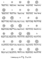
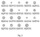
- the calculation unit 8 is followed by a so-called block generator 9, to which the data of the calculation unit 8 are fed, and in which the individual laser shot coordinates for the removal of each individual surface layer that can be specified as desired (cf., for example, FIG.
- any area captured by a step x) are assigned to one another in such a way (that they are grouped into blocks) in such a way that successive laser spots in the individual ablation area are placed at a distance from one another in such a way that they do not overlap, which is advantageously achieved via a random distribution and the advantage of using the device tends to minimize the thermal load in the erosion area.
- the block generator 9 is followed by a sequence generator 10, in which the individual blocks formed in the block generator 9 are combined and brought into a sequence on which the invention is based. This sequence represents a block sequence which, based on FIG.
- step 3 shows the processing sub-steps (steps 1 to 6; 7-12; 13-18; 19-24; 25-30; 31-36; 37-42; 43-48; 49 -54).
- Each of these processing sub-steps represents a complete partial correction in itself.
- the defined block sequence sent from the sequence generator 10 to the control unit 5 through the interaction of previously mentioned units serves on the one hand to control the laser beam deflection unit 3 and on the other hand to control the beam shaping unit 2 and there in particular for control an aperture 21 provided in the beam shaping unit 2 and whose opening can be changed, the function of which is explained in more detail when the device is used.
- a central computer unit 11 which, depending on the control data leaving the control unit 5, connects and controls at least the laser unit 1, the beam shaping unit 2; 21 and the laser beam deflection unit 3 are coordinated in a predeterminable manner.
- the first and second input unit 6; 7, the calculation unit 8, the block generator 9, the sequence generator 10 and the control unit 5 are assigned to a second computer unit connected to the central computer 11. It is also possible to integrate the units mentioned in the central computer 11.
- a monitoring unit 12 is advantageously provided, which detects random deflection movements of the surface 4 to be processed and forwards corresponding correction signals to the laser beam deflection unit 3 via the control unit 5.
- a monitoring unit is described, for example, by A. Unkroth et al. in "Corneal surgery by two-dimensionally scanning of a low-energy excimer laser beam” SPIE Vol. 2126 Ophthalmic Technol. IV 1994 pp. 217ff. described.
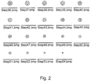
- the example of the sequence of required processing steps for a myopia correction in the case of the application of the so-called Represents small spot scanning according to the prior art become.
- the individual ablation layers are continuous Rows arranged as in a spherical treatment Short-sightedness would be used in small spot scanning.
- the individual points indicate the center points of the individual Laser ablation of a circular laser beam with about 1-2 mm Diameter.
- a suitable overlap factor and a suitable, e.g. Gaussian beam profile results from all of the individual Laser shots per layer with respect to those to be generated Correction of some kind, but more refractive evenly Tissue removal within an area.
- Step1 a first step
- Step2 four laser spots in succession corresponding to the Requirement a) are set. So that means after setting each current laser spots are preferably only set in each case laser spots further away from him, causing local overheating, due to the placement of several spots in a small area, effective is prevented. Preference is given only to the following ones Removal layers (Step2, ..., n) a partial overlap of previous ones Removal areas approved by the control unit 5.
- Step2 several laser spots set in a slightly enlarged area, being the four laser spots set in the middle in accordance with Step1 in the example Step2 is already offset to the one after Step1.
- the laser 1 and / or the beam shaping unit 2 are actuated accordingly is carried out at least once with first parameters, after which the steps according to a) to c) are repeated repeatedly with changed parameters until a processing state corresponding to a partial correction according to the provision d1) or a complete correction according to the provision d2) is achieved.
- the laser spots with different spot diameters. At least one machining cycle a) to c) is advantageously carried out with a large laser spot diameter and others with smaller laser spot diameters.
- machining cycles with different laser spot diameters ensures both the realization of short machining times and a shaping removal in accordance with the desired parameters. If, for example, a laser beam with a diameter of 1 mm is used during the fine removal, at least in areas in which a larger removal is required, at least once a shaping removal in accordance with the requirements of a) to c) with a larger laser beam diameter , for example with 2 mm.
- the shortening of the Processing time while backing up the desired one Realize removal in that between laser 1 and processing surface 4 a the energy density of the laser radiation influencing element is arranged.
- Such an element can e.g. be a mechanical or variable optical attenuator. Also lies it within the scope of the invention at least one processing cycle a) to c) with high energy density and others with low energy density perform.
- the invention is not based on the exemplary embodiments described limited. So it is e.g. also within the scope of the invention that individual Ablation areas by means of the beam shaping unit 2; 21 and / or the laser beam deflection unit 3 by self-contained ring tracks or column-like ablation zones are formed, which is characterized by the removal according to the invention basically any, from the spherical Have the lens correction deviate from the target value.
- the lasers proposed for the PRK or the LASIK method come into consideration.
- the laser is preferably an excimer laser with a wavelength of 193 nm or an Er: YAG laser with a wavelength of 2940 nm.
- the energy density applied to the surface to be processed is preferably 100-300 mJ / cm 2 in an embodiment according to the invention.
- the laser spot on the surface 4 to be machined is largely circular and has a laser spot diameter of 3 mm for at least one ablation layer. Additional layers are removed with a laser spot diameter of 1 mm.
- the beam profile can in particular have a Gaussian distribution here, but a pot-shaped distribution is also possible.
- the large area To carry out removal with a Gaussian distribution and the To choose distribution with the smaller diameter in a pot shape allows both to realize continuous transition to the untreated area than irregularities in the cornea, e.g. Treat scars.
Landscapes
- Optics & Photonics (AREA)
- Physics & Mathematics (AREA)
- Health & Medical Sciences (AREA)
- Engineering & Computer Science (AREA)
- Ophthalmology & Optometry (AREA)
- Life Sciences & Earth Sciences (AREA)
- Veterinary Medicine (AREA)
- Biomedical Technology (AREA)
- Heart & Thoracic Surgery (AREA)
- Vascular Medicine (AREA)
- Nuclear Medicine, Radiotherapy & Molecular Imaging (AREA)
- Animal Behavior & Ethology (AREA)
- General Health & Medical Sciences (AREA)
- Public Health (AREA)
- Surgery (AREA)
- Plasma & Fusion (AREA)
- Mechanical Engineering (AREA)
- Laser Beam Processing (AREA)
- Laser Surgery Devices (AREA)
- Absorbent Articles And Supports Therefor (AREA)
- Shaping Of Tube Ends By Bending Or Straightening (AREA)
- Eyeglasses (AREA)
Claims (7)
- Dispositif destiné au façonnage de couches superficielles, en particulier de lentilles, par ablation laser, comprenant un laser pulsé tel qu'il est normalement utilisé pour le balayage au laser, d'une longueur d'onde et de l'énergie appropriées, une unité de mise en forme du faisceau laser (2) et un dispositif de déviation du faisceau laser (3) adapté à la séquence d'impulsions et assurant la déviation du faisceau laser pour l'orienter de sorte qu'il frappe la couche superficielle à façonner (4), en assurant que l'unité de déviation du faisceau laser (3) et l'unité de mise en forme du faisceau laser (2) peuvent être pilotées depuis une unité de pilotage (5) avec la contributionde manière qu'une séquence de données regroupées provenant du générateur de séquencement (10) pilote aussi bien l'unité de déviation du faisceau laser (3) que l'unité mise en forme du faisceau (2) de sorte qu'il peut être assuré qu'à chaque séquence de données regroupées correspond, sur l'ensemble de 1a couche superficielle à façonner, une correction partielle complète de la couche superficielle à modeler (4).d'une première unité de chargement (6) réunissant tous les paramètres d'origine relatifs à la surface à façonner,d'une deuxième unité de chargement (7) qui saisit et mémorise les données, de préférence celles se référant au laser telles que le diamètre du faisceau laser, la densité énergique, la répartition énergique et les facteurs régissant la superposition admissible pour certains spots,d'un ordinateur (8) mémorisant les données transmises par la première et la deuxième unité de chargement (6; 7) et assurant la coordination et l'interaction des différentes coordonnées caractérisant les attaques individuels des spots laser avec prise en considération de la totalité de la couche à remodeler (4) par ablation,d'un générateur de séquences (9) destinés à recevoir toutes les données traitées et transmises par l'ordinateur (8) et assurant la coordination et l'interaction des coordonnées relatives aux attaques individuelles du laser pour obtenir l'ablation d'une couche individuelle librement prédéfinie,d'un générateur de séquencement (10) prévu auquel sont transmises toutes les données regroupées sous forme de séquences générées par le générateur de séquences (9) et se référant à une zone d'ablation individuelle précise, pour prédéterminer le séquencement du traitement;
- Le Dispositif suivant la revendication 1 est caractérisé en ce que l'unité mise en forme du faisceau laser (2) comprend au moins un élément étant en mesure de modifier la puissance et/ou la densité énergique et/ou le profil de l'impact du spot laser sur la couche superficielle à façonner.
- Le dispositif suivant la revendication 2 est caractérisé en ce que l'élément intégré dans l'unité de mise en forme du faisceau (2) est un diaphragme (21).
- Le dispositif suivant la revendication 2 est caractérisé en ce que l'élément intégré dans l'unité de mise en forme du faisceau est un diaphragme.
- Le dispositif suivant la revendication 1 est caractérisé en ce qu' une unité de contrôle (12) est prévue qui saisit les mouvements de déviation de la couche superficielle à façonner (4) et transmet par l'intermédiaire de l'unité de pilotage (5) les signaux de correction respectifs à l'unité de déviation du faisceau (3).
- Le dispositif suivant la revendication 1 est caractérisé en ce que la première et la deuxième unité de chargement (6; 7), l'ordinateur (8), le générateur de séquences (9), le générateur de séquencement (10) et l'unité de pilotage (5) sont reliés à un deuxième ordinateur qui lui-même est connecté à l'unité centrale (11).
- Le dispositif suivant la revendication 1 est caractérisé en ce que la première et la deuxième unité de chargement (6; 7), l'ordinateur (8), le générateur de séquences (9), le générateur de séquencement (10) et l'unité de pilotage (5) sont intégrés dans l'unité centrale (11).
Priority Applications (1)
| Application Number | Priority Date | Filing Date | Title |
|---|---|---|---|
| EP02007539A EP1234561A3 (fr) | 1996-10-26 | 1997-10-22 | Procédé de faconnage d'une surface, en particulier d'une lentille |
Applications Claiming Priority (5)
| Application Number | Priority Date | Filing Date | Title |
|---|---|---|---|
| DE19644664 | 1996-10-26 | ||
| DE19644664 | 1996-10-26 | ||
| DE19727573 | 1997-06-28 | ||
| DE19727573A DE19727573C1 (de) | 1996-10-26 | 1997-06-28 | Vorrichtung und Verfahren zur Formgebung von Oberflächen, insbesondere von Linsen |
| PCT/EP1997/005828 WO1998018415A1 (fr) | 1996-10-26 | 1997-10-22 | Procede et dispositif de façonnage de surfaces |
Related Child Applications (1)
| Application Number | Title | Priority Date | Filing Date |
|---|---|---|---|
| EP02007539A Division EP1234561A3 (fr) | 1996-10-26 | 1997-10-22 | Procédé de faconnage d'une surface, en particulier d'une lentille |
Publications (2)
| Publication Number | Publication Date |
|---|---|
| EP0951260A1 EP0951260A1 (fr) | 1999-10-27 |
| EP0951260B1 true EP0951260B1 (fr) | 2002-09-18 |
Family
ID=26030818
Family Applications (1)
| Application Number | Title | Priority Date | Filing Date |
|---|---|---|---|
| EP97945865A Expired - Lifetime EP0951260B1 (fr) | 1996-10-26 | 1997-10-22 | Procede et dispositif de faconnage de surfaces |
Country Status (7)
| Country | Link |
|---|---|
| US (1) | US6290695B1 (fr) |
| EP (1) | EP0951260B1 (fr) |
| JP (2) | JP4130231B2 (fr) |
| AT (1) | ATE224172T1 (fr) |
| AU (1) | AU5120598A (fr) |
| ES (1) | ES2186927T3 (fr) |
| WO (1) | WO1998018415A1 (fr) |
Families Citing this family (10)
| Publication number | Priority date | Publication date | Assignee | Title |
|---|---|---|---|---|
| US6497701B2 (en) * | 1999-04-30 | 2002-12-24 | Visx, Incorporated | Method and system for ablating surfaces with partially overlapping craters having consistent curvature |
| US20040176718A1 (en) * | 1999-06-07 | 2004-09-09 | Joachim Fiedler | Suction removal of waste products in the ablation of biological tissue |
| DE10024079A1 (de) * | 2000-05-17 | 2001-11-22 | Asclepion Meditec Ag | Verfahren und Vorrichtung zur Kontrolle der Energie und/oder Position eines gepulsten und gescannten Laserstrahles |
| DE10130278B4 (de) * | 2001-06-26 | 2005-11-03 | Carl Zeiss Meditec Ag | Verfahren und Vorrichtung zur Darstellung eines Operationsgebietes bei Laseroperationen |
| DE10202036A1 (de) * | 2002-01-18 | 2003-07-31 | Zeiss Carl Meditec Ag | Femtosekunden Lasersystem zur präzisen Bearbeitung von Material und Gewebe |
| DE102004021680A1 (de) | 2004-04-30 | 2005-11-24 | Carl Zeiss Meditec Ag | Anordnung zum Entfernen von Abprodukten bei der Ablation von biologischem Gewebe |
| KR100760001B1 (ko) * | 2005-01-28 | 2007-09-27 | 한미반도체 주식회사 | 반도체 제조 공정용 흡착패드 가공장치 및 가공방법 |
| ATE516786T1 (de) | 2005-02-15 | 2011-08-15 | Zeiss Carl Meditec Ag | Verfahren zur herstellung eines ablationsprogramms, in abhängigkeit von der form eines laserstrahlprofils und von einer neigung der zu ablatierenden oberfläche ; mittel zur durchführung der verfahren |
| EP2240108B1 (fr) * | 2008-01-09 | 2015-04-29 | Alcon LenSx, Inc. | Fragmentation de tissu par laser photodisruptif |
| CA3172603A1 (fr) * | 2013-01-16 | 2014-07-24 | Amo Development, Llc | Procedes de coupe au laser robuste pour chirurgie ophtalmique |
Family Cites Families (13)
| Publication number | Priority date | Publication date | Assignee | Title |
|---|---|---|---|---|
| ATE28974T1 (de) * | 1982-12-09 | 1987-09-15 | Ibm | Abtragung biologischen materials mittels photochemischer zersetzung. |
| US4669466A (en) | 1985-01-16 | 1987-06-02 | Lri L.P. | Method and apparatus for analysis and correction of abnormal refractive errors of the eye |
| GB2221162A (en) * | 1988-07-11 | 1990-01-31 | Mezhotras N Tekh Mikrochirurg | Device for correcting ocular refraction anomalies |
| US6099522A (en) * | 1989-02-06 | 2000-08-08 | Visx Inc. | Automated laser workstation for high precision surgical and industrial interventions |
| FR2655837A1 (fr) * | 1989-12-15 | 1991-06-21 | Hanna Khalil | Masque de traitement de surface et dispositif de chirurgie de l'óoeil ou de realisation de lentille optique par laser. |
| CA2073802C (fr) * | 1991-08-16 | 2003-04-01 | John Shimmick | Methode et appareil permettant d'apporter simultanement des corrections cylindriques et spheriques a la cornee |
| EP0630205A4 (fr) * | 1992-02-27 | 1995-06-14 | Phoenix Laser Systems Inc | Poste de travail automatise a laser pour interventions industrielles et chirurgicales de haute precision. |
| DE4232915A1 (de) * | 1992-10-01 | 1994-04-07 | Hohla Kristian | Vorrichtung zur Formung der Cornea durch Abtragen von Gewebe |
| US6090100A (en) | 1992-10-01 | 2000-07-18 | Chiron Technolas Gmbh Ophthalmologische Systeme | Excimer laser system for correction of vision with reduced thermal effects |
| US5520679A (en) | 1992-12-03 | 1996-05-28 | Lasersight, Inc. | Ophthalmic surgery method using non-contact scanning laser |
| CA2112843A1 (fr) | 1993-02-04 | 1994-08-05 | Richard C. Ujazdowski | Laser picoseconde a frequence de repetition variable |
| CO4230054A1 (es) * | 1993-05-07 | 1995-10-19 | Visx Inc | Metodo y sistemas para tratamiento con laser de errores refractivos utilizando formacion de imagenes de desplazamiento |
| US5599340A (en) * | 1994-12-09 | 1997-02-04 | Simon; Gabriel | Laser beam ophthalmological surgery method and apparatus |
-
1997
- 1997-10-22 AU AU51205/98A patent/AU5120598A/en not_active Abandoned
- 1997-10-22 WO PCT/EP1997/005828 patent/WO1998018415A1/fr not_active Ceased
- 1997-10-22 ES ES97945865T patent/ES2186927T3/es not_active Expired - Lifetime
- 1997-10-22 EP EP97945865A patent/EP0951260B1/fr not_active Expired - Lifetime
- 1997-10-22 JP JP52001098A patent/JP4130231B2/ja not_active Expired - Lifetime
- 1997-10-22 US US09/269,963 patent/US6290695B1/en not_active Expired - Lifetime
- 1997-10-22 AT AT97945865T patent/ATE224172T1/de not_active IP Right Cessation
-
2007
- 2007-06-12 JP JP2007155799A patent/JP2007328349A/ja active Pending
Also Published As
| Publication number | Publication date |
|---|---|
| JP4130231B2 (ja) | 2008-08-06 |
| JP2007328349A (ja) | 2007-12-20 |
| AU5120598A (en) | 1998-05-22 |
| ATE224172T1 (de) | 2002-10-15 |
| ES2186927T3 (es) | 2003-05-16 |
| EP0951260A1 (fr) | 1999-10-27 |
| JP2001502585A (ja) | 2001-02-27 |
| US6290695B1 (en) | 2001-09-18 |
| WO1998018415A1 (fr) | 1998-05-07 |
Similar Documents
| Publication | Publication Date | Title |
|---|---|---|
| DE19727573C1 (de) | Vorrichtung und Verfahren zur Formgebung von Oberflächen, insbesondere von Linsen | |
| DE69326013T2 (de) | Vorrichtung zur formung der cornea mittels grossflächiger laser-abtragung | |
| DE69535218T2 (de) | Laser-Hornhaut-Skulptursystem | |
| DE60126435T2 (de) | Apparat zur behandlung von presbyopie und anderer augenerkrankungen mit faser-gekoppelten lasern | |
| DE69122349T2 (de) | Lasergerät zu thermischer Hornhautplastik | |
| DE69506128T2 (de) | Vorrichtung zur reprofilierung der augenhornhaut | |
| DE69024558T2 (de) | Laser-Abschmelzung von Oberflächen | |
| EP2434998B1 (fr) | Système d'ophtalmologie par chirurgie laser | |
| EP2407132B1 (fr) | Dispositif de préparation d'un oeil pour l'introduction d'un photo-stabilisateur | |
| DE19746483A1 (de) | Vorrichtung zur Formgebung von Objekten | |
| DE102012018421A1 (de) | Augenchirurgische Refraktionskorrektur | |
| CH704435B1 (de) | Vorrichtung zur Materialbearbeitung mittels Laserstrahlung. | |
| EP0951260B1 (fr) | Procede et dispositif de faconnage de surfaces | |
| EP3050544B1 (fr) | Dispositif et procede de traitement de materiau a l'aide d'un rayon laser | |
| EP3695818B1 (fr) | Programme d`ordinateur de commande d'un laser chirurgical ophtalmique et dispositif d'éclairage | |
| EP1834615B1 (fr) | Programme de commande en chirurgie ophtalmique | |
| EP0595823B1 (fr) | Dispositif de photo-ablation douce et precise pour la chirurgie photorefractive | |
| DE3615042C2 (de) | Vorrichtung zur Korrektur oder Neugestaltung der Wölbung der Augnhornhaut durch Photoablation von Laserstrahlung | |
| EP2410960B1 (fr) | Dispositif pour lasik | |
| WO2023057443A1 (fr) | Dispositif de planification servant à générer des données de commande pour un dispositif laser d'un dispositif de traitement pour la correction réfractive d'un oeil, dispositif de traitement, procédé de génération de données de commande et procédé de correction réfractive | |
| DE69220249T2 (de) | Lasermodelliervorrichtung zur astigmatismuskorrektur | |
| DE102021100509B4 (de) | Verfahren zur Steuerung eines augenchirurgischen Lasers, Computerprogrammprodukt sowie Behandlungsvorrichtung | |
| DE102023118293B4 (de) | Verfahren zum bereitstellen von steuerdaten für einen ophthalmologischen laser einer behandlungsvorrichtung | |
| DE102020123611B4 (de) | System zur Steuerung eines augenchirurgischen Lasers und Verfahren zur Ermittlung von Steuerdaten zur Steuerung eines augenchirurgischen Lasers | |
| DE69227528T2 (de) | Astigmastische laseroberflächenablation |
Legal Events
| Date | Code | Title | Description |
|---|---|---|---|
| PUAI | Public reference made under article 153(3) epc to a published international application that has entered the european phase |
Free format text: ORIGINAL CODE: 0009012 |
|
| 17P | Request for examination filed |
Effective date: 19990504 |
|
| AK | Designated contracting states |
Kind code of ref document: A1 Designated state(s): AT BE CH DE DK ES FI FR GB GR IE IT LI LU MC NL PT SE |
|
| AX | Request for extension of the european patent |
Free format text: AL PAYMENT 19990504;LT PAYMENT 19990504;LV PAYMENT 19990504;RO PAYMENT 19990504;SI PAYMENT 19990504 |
|
| 17Q | First examination report despatched |
Effective date: 19991216 |
|
| GRAG | Despatch of communication of intention to grant |
Free format text: ORIGINAL CODE: EPIDOS AGRA |
|
| RAP1 | Party data changed (applicant data changed or rights of an application transferred) |
Owner name: ASCLEPION-MEDITEC AG |
|
| GRAG | Despatch of communication of intention to grant |
Free format text: ORIGINAL CODE: EPIDOS AGRA |
|
| GRAH | Despatch of communication of intention to grant a patent |
Free format text: ORIGINAL CODE: EPIDOS IGRA |
|
| GRAH | Despatch of communication of intention to grant a patent |
Free format text: ORIGINAL CODE: EPIDOS IGRA |
|
| GRAA | (expected) grant |
Free format text: ORIGINAL CODE: 0009210 |
|
| AK | Designated contracting states |
Kind code of ref document: B1 Designated state(s): AT BE CH DE DK ES FI FR GB GR IE IT LI LU MC NL PT SE |
|
| AX | Request for extension of the european patent |
Free format text: AL PAYMENT 19990504;LT PAYMENT 19990504;LV PAYMENT 19990504;RO PAYMENT 19990504;SI PAYMENT 19990504 |
|
| PG25 | Lapsed in a contracting state [announced via postgrant information from national office to epo] |
Ref country code: NL Free format text: LAPSE BECAUSE OF FAILURE TO SUBMIT A TRANSLATION OF THE DESCRIPTION OR TO PAY THE FEE WITHIN THE PRESCRIBED TIME-LIMIT Effective date: 20020918 Ref country code: IE Free format text: LAPSE BECAUSE OF FAILURE TO SUBMIT A TRANSLATION OF THE DESCRIPTION OR TO PAY THE FEE WITHIN THE PRESCRIBED TIME-LIMIT Effective date: 20020918 Ref country code: GR Free format text: LAPSE BECAUSE OF FAILURE TO SUBMIT A TRANSLATION OF THE DESCRIPTION OR TO PAY THE FEE WITHIN THE PRESCRIBED TIME-LIMIT Effective date: 20020918 Ref country code: FI Free format text: LAPSE BECAUSE OF FAILURE TO SUBMIT A TRANSLATION OF THE DESCRIPTION OR TO PAY THE FEE WITHIN THE PRESCRIBED TIME-LIMIT Effective date: 20020918 |
|
| REF | Corresponds to: |
Ref document number: 224172 Country of ref document: AT Date of ref document: 20021015 Kind code of ref document: T |
|
| REG | Reference to a national code |
Ref country code: GB Ref legal event code: FG4D Free format text: NOT ENGLISH |
|
| REG | Reference to a national code |
Ref country code: CH Ref legal event code: EP |
|
| REG | Reference to a national code |
Ref country code: IE Ref legal event code: FG4D Free format text: GERMAN |
|
| PG25 | Lapsed in a contracting state [announced via postgrant information from national office to epo] |
Ref country code: LU Free format text: LAPSE BECAUSE OF NON-PAYMENT OF DUE FEES Effective date: 20021022 Ref country code: AT Free format text: LAPSE BECAUSE OF NON-PAYMENT OF DUE FEES Effective date: 20021022 |
|
| REF | Corresponds to: |
Ref document number: 59708284 Country of ref document: DE Date of ref document: 20021024 |
|
| PG25 | Lapsed in a contracting state [announced via postgrant information from national office to epo] |
Ref country code: LI Free format text: LAPSE BECAUSE OF NON-PAYMENT OF DUE FEES Effective date: 20021031 Ref country code: CH Free format text: LAPSE BECAUSE OF NON-PAYMENT OF DUE FEES Effective date: 20021031 Ref country code: BE Free format text: LAPSE BECAUSE OF NON-PAYMENT OF DUE FEES Effective date: 20021031 |
|
| RAP2 | Party data changed (patent owner data changed or rights of a patent transferred) |
Owner name: CARL ZEISS MEDITEC AG |
|
| PG25 | Lapsed in a contracting state [announced via postgrant information from national office to epo] |
Ref country code: SE Free format text: LAPSE BECAUSE OF FAILURE TO SUBMIT A TRANSLATION OF THE DESCRIPTION OR TO PAY THE FEE WITHIN THE PRESCRIBED TIME-LIMIT Effective date: 20021218 Ref country code: DK Free format text: LAPSE BECAUSE OF FAILURE TO SUBMIT A TRANSLATION OF THE DESCRIPTION OR TO PAY THE FEE WITHIN THE PRESCRIBED TIME-LIMIT Effective date: 20021218 |
|
| PG25 | Lapsed in a contracting state [announced via postgrant information from national office to epo] |
Ref country code: PT Free format text: LAPSE BECAUSE OF FAILURE TO SUBMIT A TRANSLATION OF THE DESCRIPTION OR TO PAY THE FEE WITHIN THE PRESCRIBED TIME-LIMIT Effective date: 20021219 |
|
| REG | Reference to a national code |
Ref country code: GB Ref legal event code: 732E |
|
| GBT | Gb: translation of ep patent filed (gb section 77(6)(a)/1977) |
Effective date: 20021223 |
|
| NLT2 | Nl: modifications (of names), taken from the european patent patent bulletin |
Owner name: CARL ZEISS MEDITEC AG |
|
| LTIE | Lt: invalidation of european patent or patent extension |
Effective date: 20020918 |
|
| NLV1 | Nl: lapsed or annulled due to failure to fulfill the requirements of art. 29p and 29m of the patents act | ||
| ET | Fr: translation filed | ||
| BERE | Be: lapsed |
Owner name: *ASCLEPION-MEDITEC A.G. Effective date: 20021031 |
|
| PG25 | Lapsed in a contracting state [announced via postgrant information from national office to epo] |
Ref country code: MC Free format text: LAPSE BECAUSE OF NON-PAYMENT OF DUE FEES Effective date: 20030501 |
|
| REG | Reference to a national code |
Ref country code: ES Ref legal event code: FG2A Ref document number: 2186927 Country of ref document: ES Kind code of ref document: T3 |
|
| REG | Reference to a national code |
Ref country code: IE Ref legal event code: FD4D Ref document number: 0951260E Country of ref document: IE |
|
| REG | Reference to a national code |
Ref country code: CH Ref legal event code: PL |
|
| PLBE | No opposition filed within time limit |
Free format text: ORIGINAL CODE: 0009261 |
|
| STAA | Information on the status of an ep patent application or granted ep patent |
Free format text: STATUS: NO OPPOSITION FILED WITHIN TIME LIMIT |
|
| 26N | No opposition filed |
Effective date: 20030619 |
|
| REG | Reference to a national code |
Ref country code: FR Ref legal event code: PLFP Year of fee payment: 19 |
|
| REG | Reference to a national code |
Ref country code: FR Ref legal event code: PLFP Year of fee payment: 20 |
|
| PGFP | Annual fee paid to national office [announced via postgrant information from national office to epo] |
Ref country code: DE Payment date: 20161020 Year of fee payment: 20 Ref country code: GB Payment date: 20161020 Year of fee payment: 20 Ref country code: FR Payment date: 20161020 Year of fee payment: 20 |
|
| PGFP | Annual fee paid to national office [announced via postgrant information from national office to epo] |
Ref country code: IT Payment date: 20161024 Year of fee payment: 20 Ref country code: ES Payment date: 20161011 Year of fee payment: 20 |
|
| REG | Reference to a national code |
Ref country code: DE Ref legal event code: R071 Ref document number: 59708284 Country of ref document: DE |
|
| REG | Reference to a national code |
Ref country code: GB Ref legal event code: PE20 Expiry date: 20171021 |
|
| PG25 | Lapsed in a contracting state [announced via postgrant information from national office to epo] |
Ref country code: GB Free format text: LAPSE BECAUSE OF EXPIRATION OF PROTECTION Effective date: 20171021 |
|
| REG | Reference to a national code |
Ref country code: ES Ref legal event code: FD2A Effective date: 20180507 |
|
| PG25 | Lapsed in a contracting state [announced via postgrant information from national office to epo] |
Ref country code: ES Free format text: LAPSE BECAUSE OF EXPIRATION OF PROTECTION Effective date: 20171023 |