EP0951261B1 - Dispositif d'equilibrage de pression servant de prothese d'une trompe d'eustache - Google Patents
Dispositif d'equilibrage de pression servant de prothese d'une trompe d'eustache Download PDFInfo
- Publication number
- EP0951261B1 EP0951261B1 EP98902947A EP98902947A EP0951261B1 EP 0951261 B1 EP0951261 B1 EP 0951261B1 EP 98902947 A EP98902947 A EP 98902947A EP 98902947 A EP98902947 A EP 98902947A EP 0951261 B1 EP0951261 B1 EP 0951261B1
- Authority
- EP
- European Patent Office
- Prior art keywords
- pressure compensation
- compensation device
- filter
- tube
- middle ear
- Prior art date
- Legal status (The legal status is an assumption and is not a legal conclusion. Google has not performed a legal analysis and makes no representation as to the accuracy of the status listed.)
- Expired - Lifetime
Links
- 210000002388 eustachian tube Anatomy 0.000 title claims abstract description 10
- 210000000959 ear middle Anatomy 0.000 claims abstract description 23
- 239000012528 membrane Substances 0.000 claims abstract description 12
- 210000000988 bone and bone Anatomy 0.000 claims description 5
- 241000894006 Bacteria Species 0.000 claims description 2
- 241000700605 Viruses Species 0.000 claims 1
- 238000005266 casting Methods 0.000 claims 1
- 239000000835 fiber Substances 0.000 claims 1
- 239000011888 foil Substances 0.000 claims 1
- 229920001296 polysiloxane Polymers 0.000 claims 1
- XLYOFNOQVPJJNP-UHFFFAOYSA-N water Substances O XLYOFNOQVPJJNP-UHFFFAOYSA-N 0.000 abstract description 6
- 238000000926 separation method Methods 0.000 abstract description 2
- 239000012510 hollow fiber Substances 0.000 description 15
- 210000004379 membrane Anatomy 0.000 description 10
- 210000003454 tympanic membrane Anatomy 0.000 description 8
- 244000052616 bacterial pathogen Species 0.000 description 6
- 230000005540 biological transmission Effects 0.000 description 5
- 238000009423 ventilation Methods 0.000 description 4
- 230000008878 coupling Effects 0.000 description 3
- 238000010168 coupling process Methods 0.000 description 3
- 238000005859 coupling reaction Methods 0.000 description 3
- 238000010276 construction Methods 0.000 description 2
- 239000000428 dust Substances 0.000 description 2
- 238000000034 method Methods 0.000 description 2
- 206010008642 Cholesteatoma Diseases 0.000 description 1
- 230000004888 barrier function Effects 0.000 description 1
- 230000001684 chronic effect Effects 0.000 description 1
- 208000024035 chronic otitis media Diseases 0.000 description 1
- 239000011362 coarse particle Substances 0.000 description 1
- 238000011109 contamination Methods 0.000 description 1
- 230000010339 dilation Effects 0.000 description 1
- 201000010099 disease Diseases 0.000 description 1
- 208000037265 diseases, disorders, signs and symptoms Diseases 0.000 description 1
- 210000003027 ear inner Anatomy 0.000 description 1
- 230000000694 effects Effects 0.000 description 1
- 239000003292 glue Substances 0.000 description 1
- PCHJSUWPFVWCPO-UHFFFAOYSA-N gold Chemical compound [Au] PCHJSUWPFVWCPO-UHFFFAOYSA-N 0.000 description 1
- 210000003128 head Anatomy 0.000 description 1
- 238000002513 implantation Methods 0.000 description 1
- 208000015181 infectious disease Diseases 0.000 description 1
- 230000036512 infertility Effects 0.000 description 1
- 239000007788 liquid Substances 0.000 description 1
- 230000036244 malformation Effects 0.000 description 1
- 239000000463 material Substances 0.000 description 1
- 230000000149 penetrating effect Effects 0.000 description 1
- 239000004576 sand Substances 0.000 description 1
- 239000003566 sealing material Substances 0.000 description 1
- 210000003625 skull Anatomy 0.000 description 1
- 210000001050 stape Anatomy 0.000 description 1
- 238000011477 surgical intervention Methods 0.000 description 1
Images

Classifications
-
- A—HUMAN NECESSITIES
- A61—MEDICAL OR VETERINARY SCIENCE; HYGIENE
- A61F—FILTERS IMPLANTABLE INTO BLOOD VESSELS; PROSTHESES; DEVICES PROVIDING PATENCY TO, OR PREVENTING COLLAPSING OF, TUBULAR STRUCTURES OF THE BODY, e.g. STENTS; ORTHOPAEDIC, NURSING OR CONTRACEPTIVE DEVICES; FOMENTATION; TREATMENT OR PROTECTION OF EYES OR EARS; BANDAGES, DRESSINGS OR ABSORBENT PADS; FIRST-AID KITS
- A61F11/00—Methods or devices for treatment of the ears or hearing sense; Non-electric hearing aids; Methods or devices for enabling ear patients to achieve auditory perception through physiological senses other than hearing sense; Protective devices for the ears, carried on the body or in the hand
- A61F11/20—Ear surgery
- A61F11/202—Surgical middle-ear ventilation or drainage, e.g. permanent; Implants therefor
Definitions
- the invention relates to a pressure compensation device, which as a prosthetic Replacement for an Eustachian tube is implantable.
- a prosthetic replacement for the Eustachian tube is known from WO-A-9310729. It describes a ventilation pipe which is used as a pressure compensation device for the middle ear is provided.
- the ventilation pipe comprises tightly connected Outside, inside and filter parts.
- the inner part is firmly screwed into the skull bone anchored.
- the outer part is screwed to the inner part tightly connected.
- the filter part can be plugged onto the outer end of the outer part become.
- the outside of the filter part is covered with an air-permeable, but provide a filter impermeable to germs or water etc. that leads to the outside world is arranged directed.
- This external filter part must also protect the middle ear from gross contamination prevent by dust, sand, water etc., has a rough filter effect, to protect the middle ear from infections by germs, especially to protect against To be able to protect penetrating water and germs, the filter part must be extremely fine-pored filter. Due to the external arrangement of the filter part the very fine-pored filter is strong due to clogging by coarse particles such as Dirt or dust threatened.
- the object of the present invention is to provide a pressure compensation device, which replaces the natural Eustachian tube when not for ventilation of the middle ear is available, while the lifetime used Filters are increased and sterility can be improved in the event of a filter change should.
- a pressure compensation device as a prosthetic Replacement for an Eustachian tube, with an outer part and an inner part, which are together are tightly connected via a first hose, the outer part 1. in can be anchored to one bone and one to the surrounding one.
- Skin freely accessible Has area 2. has a receptacle for a filter that is accessible from the outside and 3. has an inside connection for the first hose and the inner part has a sealed housing that is in two chambers, namely an outer chamber and an inner chamber, divided by either one Fine filter or separated from each other by a pressure compensation membrane are and of which the outer chamber via a connection to the first Hose communicates and the inner chamber via a connection for one second tube is connected, which ends in the middle ear.
- the pressure compensation device enables ventilation the tympanic cavity, i.e. the middle ear from an externally accessible one Part of the head.
- the outer part is in one Bones are inserted and waxed over to the side of the skin that it is partially protrudes externally and thus freely accessible from the outside. It will do this used a similar technique to that used for bone-implanted hearing aids is already known.
- the outer part is preferably behind the ear and arranged covered by the auricle as possible.
- the outer part serves as an air inlet, it is still responsible for coarse Dirt and water from the other parts of the pressure compensation device keep away. For this it has a filter that is in one shot of the outer part is housed and is preferably replaceable.
- the outer part is connected to the inner part via the first hose.
- the latter has the task of creating a germ-tight separation.
- the inner part has a housing that is divided into two chambers. These are either through a highly flexible but completely impermeable membrane separated from each other or connected via a fine filter.
- the Both chambers of the housing are called the outer chamber and the inner chamber referred to, the outer chamber is connected to the first hose Outer part connected.
- the inner chamber is connected to the second hose connected to the middle ear, preferably with a middle ear prosthesis provided there.
- the highly flexible membrane ensures that from the outer chamber no germs can get into the inner chamber.
- the same task has the fine filter, but it is also breathable. To that It is preferred to be able to give fine filters the largest possible filter area designed as a hollow fiber filter.
- Figure 1 is a pressure compensation device together with a middle ear prosthesis shown. Both are now described below:
- the middle ear prosthesis has an artificial eardrum 20, which is essentially has an oval cut. In terms of area, it is larger than that Area of a normal human eardrum, for example 1.5 times as much large. It is made from a biologically suitable for use as a prosthesis Cut material.
- the eardrum 20 is tightly connected to a two-part design Housing, specifically it is connected to a transmission part 22.
- This is essentially tubular. It is essentially cylindrical Area shown in Figure 1 below and a different from this from widening area, which essentially runs on a conical surface. The diameter of the cylindrical region is about 6 mm, the widening area has corresponding dimensions of about 11 mm.
- the eardrum 20 is in one plane, it runs at an angle of 37 ° to a longitudinal axis 23 of the transmission part 22. Due to the inclined position of the eardrum 20, the eardrum 20 has one larger area compared to the normal ear.
- a second ossicle part 24 is permanently attached on the inside of the eardrum 20, preferably in the center of the area.
- a commercial ossicle replacement from Richards is an exemplary embodiment GmbH used. He has a ball joint near the eardrum 20, underneath there is a hollow shaft to hold one more to be discussed first part of the ossicle.
- the second ossicle part 24 runs below the ball joint centered on the central axis of the transmission part 22nd
- a coupling part 28 also belongs to the housing slightly smaller than the transmission part 22 and together with this trained, the two parts simply, tightly and permanently connected can be, especially by plugging in the longitudinal direction and Glue.
- the coupling part 28 is essentially cylindrical Diameter is also about 6 mm. It has a free end area 30, which has a course which corresponds to the respective individual relief of the The timpani wall of a wearer of the middle ear prosthesis is reproduced as precisely as possible is.
- the patent application “device for mechanical scanning and recording the course of the timpani wall Middle ear"
- the disclosure content of this application becomes the subject of the disclosure made the present application.
- the free end region 30 is accordingly designed to be precise the timpani wall 32 rests, as can be seen from FIG. 1. To this A hermetically sealed closure is possible at this point, it low-viscosity fastening and sealing material can be used to the connection between the free end region 30 and the tympanic wall 32 to realize.
- a holding device 34 for the first ossicle part 26 provided in the coupling part 28 .
- the latter is designed as a thin gold wire that through a very small, artificially created opening 36 in a stapes footplate 38 just fits through and thus with its lower, free end area protrudes into the inner ear 40.
- the holding device 34 is a substantially diagonal Wire on which the first ossicle part 26 is or can be fixed is.
- the middle ear prosthesis is for the connection of the two ossicle parts 24, 26 and also for severing the holding device 34 requires access to the interior.
- Other Constructions without such access are possible.
- For this Access is provided in the transmission part 22, a window 42 through a cover plate 44 can be closed.
- the cover plate 44 has a connection 52. It is for a hose 54 is provided.
- the hose 54 leads to an inner part 56 a pressure compensation device.
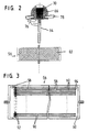
- This inner part 56 is a can-shaped Running housing, it has two chambers, namely an outer chamber 58 and an inner chamber 60. Both are through a very flexible membrane 62 hermetically separated. In another version they are through a fine filter 63, which is also tight against bacteria and microbes, but is permeable to air, separated from each other. Come as a fine filter 63 here in particular hollow fiber filters in question, see Fig. 3.
- the outer chamber 58 is connected to an outer part via a further hose 64 66 connected. It is anchored in a bone 76 and partially from accessible from outside, see skin 78. A construction is used here, as it is similar to so-called bone-conductive hearing aids.
- the outer part 66 has a recess 68 into which a filter 70 is inserted. This is preferably interchangeable.
- the filter 70 prevents water, Coarse dirt etc. can get into the hose 64.
- the barrier against Germs and the like are replaced by membrane 62 or that in their place pedaling fine filter reached.
- the inner part is not provided with a highly flexible membrane 62, rather the two Chambers 58, 60 are now separated from one another by a fine filter 63. This is designed so that no germs from the outer chamber 58 in the Inner chamber 60 can reach.
- FIG. 3 shows an inner part, in the housing of which a large number of hollow fibers 90 are arranged. Together they form the fine filter. They run essentially parallel to each other, they can lie close to each other, because of that their circular shape between the individual hollow fibers free spaces remain belong to the inner chamber 60 in the illustration shown.
- the inner chamber can but are alternatively connected to the interior of the hollow fibers 90.
- the hollow fibers 90 are all of one at the left end region Plug 92 encapsulated that access to their interiors seen from the left freely remains.
- the plug 92 surrounds each individual hollow fiber tightly in the area of its outer jacket and closes tightly against the inner wall of the housing.
- Each individual hollow fiber 90 is closed at the right end region, for example by immersing it in an appropriate liquid plastic or by squeezing it together. This closure is shown in the figure by individual plugs 94. They ensure that each individual hollow fiber is at its right end area (in the Figure 3) is hermetically sealed.
- Hollow fiber membranes of the type in question here are, for example, from the US patent 4,781,733 including that listed on the front of this specification State of the art known.
Landscapes
- Health & Medical Sciences (AREA)
- Life Sciences & Earth Sciences (AREA)
- Engineering & Computer Science (AREA)
- Biomedical Technology (AREA)
- Acoustics & Sound (AREA)
- Biophysics (AREA)
- Otolaryngology (AREA)
- Psychology (AREA)
- Surgery (AREA)
- Physics & Mathematics (AREA)
- Heart & Thoracic Surgery (AREA)
- Vascular Medicine (AREA)
- Animal Behavior & Ethology (AREA)
- General Health & Medical Sciences (AREA)
- Public Health (AREA)
- Veterinary Medicine (AREA)
- Prostheses (AREA)
- Orthopedics, Nursing, And Contraception (AREA)
Claims (8)
- Dispositif de compensation de pression servant de prothèse d'une trompe d'Eustache, comprenant une partie extérieure (66) et une partie intérieure (56) qui sont reliées l'une à l'autre de manière étanche par un premier tuyau flexible (64), la partie extérieure (66) pouvant, premièrement, être ancrée dans un os (76) et présentant une zone librement accessible par rapport à la peau environnante (78), ayant deuxièmement un logement pour un filtre, qui est accessible de l'extérieur, et présentant troisièmement un raccord (52) situé du côté intérieur pour le premier tuyau flexible (64), et la partie intérieure (56) présentant un boítier étanche qui est divisé en deux chambres, à savoir une chambre extérieure (58) et une chambre intérieure (60) qui sont séparées l'une de l'autre soit par un filtre fin (63) soit par une membrane de compensation de pression et dont la chambre extérieure (58) communique par un raccord (52) avec le premier tuyau flexible (64) et la chambre intérieure (60) est reliée par un raccord (52) pour un deuxième tuyau flexible (54) qui se termine dans l'oreille moyenne.
- Dispositif de compensation de pression selon la revendication 1, caractérisé par le fait que le filtre est placé dans le logement de manière à pouvoir être échangé.
- Dispositif de compensation de pression selon la revendication 1, caractérisé par le fait que le filtre fin (63) est étanche aux bactéries et aux virus, mais perméable à l'air, en particulier que le filtre fin (63) est réalisé comme un filtre de fibres creuses.
- Dispositif de compensation de pression selon la revendication 1, caractérisé par le fait que les tuyaux flexibles sont réalisés en tant que tuyaux flexibles en silicone.
- Dispositif de compensation de pression selon la revendication 1, caractérisé par le fait que la membrane de compensation de pression est une feuille mince, étanche et hautement flexible.
- Dispositif de compensation de pression selon l'une des revendications 1 à 5, caractérisé par le fait que le boítier présente pour l'essentiel la forme d'une boíte.
- Dispositif de compensation de pression selon la revendication 1, caractérisé par le fait que la partie intérieure (56) est dimensionnée et réalisée de telle manière qu'elle se prête à être logée dans l'oreille moyenne.
- Dispositif de compensation de pression selon la revendication 1, caractérisé par le fait que la chambre intérieure (60) présente un filtre fin (63) et que celui-ci est réalisé par une multiplicité de fibres creuses (90), lesdites fibres creuses (90) s'étendant pour l'essentiel parallèlement l'une à l'autre, présentant pour l'essentiel la même longueur, présentant sur une zone d'extrémité respectivement une fermeture, en particulier un tampon (94) qui les ferme individuellement, et, à proximité de l'autre zone d'extrémité, les fibres étant entourées ensemble, de préférence par moulage, de manière étanche par un bouchon (92).
Applications Claiming Priority (3)
| Application Number | Priority Date | Filing Date | Title |
|---|---|---|---|
| DE19700814 | 1997-01-13 | ||
| DE19700814 | 1997-01-13 | ||
| PCT/DE1998/000072 WO1998030183A1 (fr) | 1997-01-13 | 1998-01-10 | Dispositif d'equilibrage de pression servant de prothese d'une trompe d'eustache |
Publications (2)
| Publication Number | Publication Date |
|---|---|
| EP0951261A1 EP0951261A1 (fr) | 1999-10-27 |
| EP0951261B1 true EP0951261B1 (fr) | 2002-05-15 |
Family
ID=7817218
Family Applications (1)
| Application Number | Title | Priority Date | Filing Date |
|---|---|---|---|
| EP98902947A Expired - Lifetime EP0951261B1 (fr) | 1997-01-13 | 1998-01-10 | Dispositif d'equilibrage de pression servant de prothese d'une trompe d'eustache |
Country Status (7)
| Country | Link |
|---|---|
| US (1) | US6217613B1 (fr) |
| EP (1) | EP0951261B1 (fr) |
| JP (1) | JP2001508337A (fr) |
| AT (1) | ATE217508T1 (fr) |
| AU (1) | AU5981398A (fr) |
| DE (2) | DE19800562A1 (fr) |
| WO (1) | WO1998030183A1 (fr) |
Families Citing this family (1)
| Publication number | Priority date | Publication date | Assignee | Title |
|---|---|---|---|---|
| EP1988850B1 (fr) | 2006-02-27 | 2016-10-12 | AHM Technologies, Inc. | Dispositif pour trompe d'eustache |
Family Cites Families (12)
| Publication number | Priority date | Publication date | Assignee | Title |
|---|---|---|---|---|
| SU47712A1 (ru) * | 1935-12-25 | 1936-07-31 | Н.Г. Федосов | Машина дл нанесени сло гидроизол ции в тоннеле |
| US3635798A (en) * | 1969-03-24 | 1972-01-18 | William R Kirkham | Blood and fluid culturing system |
| US4015607A (en) * | 1976-01-23 | 1977-04-05 | Wright Iii J William | Eustachian tube prosthesis and method for its implantion |
| US4645504A (en) * | 1985-05-24 | 1987-02-24 | The Regents Of The University Of California | Implantable infection barrier seal and method |
| US4781733A (en) | 1986-07-23 | 1988-11-01 | Bend Research, Inc. | Semipermeable thin-film membranes comprising siloxane, alkoxysilyl and aryloxysilyl oligomers and copolymers |
| DE3707161A1 (de) * | 1987-03-06 | 1988-09-15 | Fleischer Gerald | Ohrprothese |
| US5108464A (en) | 1989-09-19 | 1992-04-28 | Bend Research, Inc. | Countercurrent dehydration by hollow fibers |
| US5002590A (en) | 1989-09-19 | 1991-03-26 | Bend Research, Inc. | Countercurrent dehydration by hollow fibers |
| SE9103546D0 (sv) * | 1991-11-28 | 1991-11-28 | Astra Ab | Middle ear ventilation tube |
| DE4407847A1 (de) * | 1993-03-10 | 1994-09-22 | Fleischer Gerald | Mittelohr-Prothese |
| US5499970A (en) * | 1994-08-23 | 1996-03-19 | Zimmer, Inc. | Debridement tip |
| US5865183A (en) * | 1997-06-03 | 1999-02-02 | Safe Dive Ltd. | Device for equalizing pressure across the eardrum of divers |
-
1998
- 1998-01-09 DE DE19800562A patent/DE19800562A1/de not_active Withdrawn
- 1998-01-10 AU AU59813/98A patent/AU5981398A/en not_active Abandoned
- 1998-01-10 AT AT98902947T patent/ATE217508T1/de not_active IP Right Cessation
- 1998-01-10 WO PCT/DE1998/000072 patent/WO1998030183A1/fr not_active Ceased
- 1998-01-10 JP JP53046398A patent/JP2001508337A/ja not_active Ceased
- 1998-01-10 US US09/341,738 patent/US6217613B1/en not_active Expired - Fee Related
- 1998-01-10 EP EP98902947A patent/EP0951261B1/fr not_active Expired - Lifetime
- 1998-01-10 DE DE59804133T patent/DE59804133D1/de not_active Expired - Fee Related
Also Published As
| Publication number | Publication date |
|---|---|
| AU5981398A (en) | 1998-08-03 |
| WO1998030183A1 (fr) | 1998-07-16 |
| DE19800562A1 (de) | 1998-07-16 |
| EP0951261A1 (fr) | 1999-10-27 |
| ATE217508T1 (de) | 2002-06-15 |
| US6217613B1 (en) | 2001-04-17 |
| DE59804133D1 (de) | 2002-06-20 |
| JP2001508337A (ja) | 2001-06-26 |
Similar Documents
| Publication | Publication Date | Title |
|---|---|---|
| EP1017337B1 (fr) | Prothese de l'oreille moyenne | |
| DE69024408T2 (de) | Einrichtung zur Regulierung des Druckes im äusseren Ohrkanal und Einrichtung zur Unterdrückung von Tinnitus | |
| EP1833424B1 (fr) | Prothese de la chaine des osselets | |
| DE29819892U1 (de) | Gehörknöchelprothese | |
| DE2925089A1 (de) | Gelenkprothese, insbesondere kuenstliches oberschenkelhueftgelenk | |
| DE10214189B4 (de) | Vorrichtung zum Beschallen eines Trommelfells mit einer Cerumenschutzeinrichtung und Hörgerät | |
| EP0821541A2 (fr) | Prothèse auditive portable complètement dans le conduit auditif et individualisée par moulage d'un corps | |
| EP1563712B1 (fr) | Ensemble et procede pour produire une prothese auditive et prothese auditive produite selon ledit procede | |
| EP0951261B1 (fr) | Dispositif d'equilibrage de pression servant de prothese d'une trompe d'eustache | |
| DE2708526A1 (de) | Magnetvorrichtung zum halten einer prothese, insbesondere einer zahnprothese an einem knochen, insbesondere am kieferknochen | |
| EP1439733A1 (fr) | Protection de microphones pour des prothèses auditives | |
| DE3638747C1 (en) | Hearing aid | |
| DE69837803T2 (de) | Hörhilfegerät | |
| DE29904770U1 (de) | Mittelohrimplantat, ausgebildet als Teilprothese | |
| DE60221107T2 (de) | Verfahren zur herstellung einer hörhilfenhalterung und eines hilfsteils | |
| CH702586A2 (de) | Zahnersatz und Vorrichtung zum Bilden eines Zahnersatzes. | |
| DE2905183B2 (de) | Gehörknöchelchen-Endoprothese | |
| EP1521498A2 (fr) | Insert universel dans le conduit auditif pour prothèses auditives | |
| DE102014221590B4 (de) | Ohrstöpselset und Ohrstöpsel | |
| DE29722084U1 (de) | Gehörknöchelprothese | |
| DE102010011509B4 (de) | Selektiver- individueller Gehör- und Lärmschutz | |
| DE102005058772B3 (de) | Offene Otoplastik | |
| DE4406081A1 (de) | Künstliches Gehörknöchelchen | |
| DE29901585U1 (de) | Mittelohrimplantat | |
| DE2845346A1 (de) | Verbindungsmuffe, insbesondere fuer wunddrainage-schlaeuche |
Legal Events
| Date | Code | Title | Description |
|---|---|---|---|
| PUAI | Public reference made under article 153(3) epc to a published international application that has entered the european phase |
Free format text: ORIGINAL CODE: 0009012 |
|
| 17P | Request for examination filed |
Effective date: 19990813 |
|
| AK | Designated contracting states |
Kind code of ref document: A1 Designated state(s): AT BE CH DE FR GB IT LI NL SE |
|
| GRAG | Despatch of communication of intention to grant |
Free format text: ORIGINAL CODE: EPIDOS AGRA |
|
| GRAG | Despatch of communication of intention to grant |
Free format text: ORIGINAL CODE: EPIDOS AGRA |
|
| GRAG | Despatch of communication of intention to grant |
Free format text: ORIGINAL CODE: EPIDOS AGRA |
|
| GRAH | Despatch of communication of intention to grant a patent |
Free format text: ORIGINAL CODE: EPIDOS IGRA |
|
| 17Q | First examination report despatched |
Effective date: 20011004 |
|
| GRAH | Despatch of communication of intention to grant a patent |
Free format text: ORIGINAL CODE: EPIDOS IGRA |
|
| GRAA | (expected) grant |
Free format text: ORIGINAL CODE: 0009210 |
|
| AK | Designated contracting states |
Kind code of ref document: B1 Designated state(s): AT BE CH DE FR GB IT LI NL SE |
|
| PG25 | Lapsed in a contracting state [announced via postgrant information from national office to epo] |
Ref country code: NL Free format text: LAPSE BECAUSE OF FAILURE TO SUBMIT A TRANSLATION OF THE DESCRIPTION OR TO PAY THE FEE WITHIN THE PRESCRIBED TIME-LIMIT Effective date: 20020515 Ref country code: IT Free format text: LAPSE BECAUSE OF FAILURE TO SUBMIT A TRANSLATION OF THE DESCRIPTION OR TO PAY THE FEE WITHIN THE PRESCRIBED TIME-LIMIT;WARNING: LAPSES OF ITALIAN PATENTS WITH EFFECTIVE DATE BEFORE 2007 MAY HAVE OCCURRED AT ANY TIME BEFORE 2007. THE CORRECT EFFECTIVE DATE MAY BE DIFFERENT FROM THE ONE RECORDED. Effective date: 20020515 |
|
| REF | Corresponds to: |
Ref document number: 217508 Country of ref document: AT Date of ref document: 20020615 Kind code of ref document: T |
|
| REG | Reference to a national code |
Ref country code: GB Ref legal event code: FG4D Free format text: NOT ENGLISH Ref country code: CH Ref legal event code: EP |
|
| REF | Corresponds to: |
Ref document number: 59804133 Country of ref document: DE Date of ref document: 20020620 |
|
| ET | Fr: translation filed | ||
| PG25 | Lapsed in a contracting state [announced via postgrant information from national office to epo] |
Ref country code: SE Free format text: LAPSE BECAUSE OF FAILURE TO SUBMIT A TRANSLATION OF THE DESCRIPTION OR TO PAY THE FEE WITHIN THE PRESCRIBED TIME-LIMIT Effective date: 20020815 |
|
| NLV1 | Nl: lapsed or annulled due to failure to fulfill the requirements of art. 29p and 29m of the patents act | ||
| GBT | Gb: translation of ep patent filed (gb section 77(6)(a)/1977) |
Effective date: 20020916 |
|
| PG25 | Lapsed in a contracting state [announced via postgrant information from national office to epo] |
Ref country code: AT Free format text: LAPSE BECAUSE OF NON-PAYMENT OF DUE FEES Effective date: 20030110 |
|
| PG25 | Lapsed in a contracting state [announced via postgrant information from national office to epo] |
Ref country code: LI Free format text: LAPSE BECAUSE OF NON-PAYMENT OF DUE FEES Effective date: 20030131 Ref country code: CH Free format text: LAPSE BECAUSE OF NON-PAYMENT OF DUE FEES Effective date: 20030131 Ref country code: BE Free format text: LAPSE BECAUSE OF NON-PAYMENT OF DUE FEES Effective date: 20030131 |
|
| PLBE | No opposition filed within time limit |
Free format text: ORIGINAL CODE: 0009261 |
|
| STAA | Information on the status of an ep patent application or granted ep patent |
Free format text: STATUS: NO OPPOSITION FILED WITHIN TIME LIMIT |
|
| 26N | No opposition filed |
Effective date: 20030218 |
|
| REG | Reference to a national code |
Ref country code: CH Ref legal event code: PL |
|
| REG | Reference to a national code |
Ref country code: GB Ref legal event code: 732E |
|
| REG | Reference to a national code |
Ref country code: FR Ref legal event code: TP |
|
| PGFP | Annual fee paid to national office [announced via postgrant information from national office to epo] |
Ref country code: DE Payment date: 20090121 Year of fee payment: 12 |
|
| PGFP | Annual fee paid to national office [announced via postgrant information from national office to epo] |
Ref country code: GB Payment date: 20090121 Year of fee payment: 12 |
|
| PGFP | Annual fee paid to national office [announced via postgrant information from national office to epo] |
Ref country code: FR Payment date: 20090121 Year of fee payment: 12 |
|
| GBPC | Gb: european patent ceased through non-payment of renewal fee |
Effective date: 20100110 |
|
| REG | Reference to a national code |
Ref country code: FR Ref legal event code: ST Effective date: 20100930 |
|
| PG25 | Lapsed in a contracting state [announced via postgrant information from national office to epo] |
Ref country code: FR Free format text: LAPSE BECAUSE OF NON-PAYMENT OF DUE FEES Effective date: 20100201 |
|
| PG25 | Lapsed in a contracting state [announced via postgrant information from national office to epo] |
Ref country code: DE Free format text: LAPSE BECAUSE OF NON-PAYMENT OF DUE FEES Effective date: 20100803 |
|
| PG25 | Lapsed in a contracting state [announced via postgrant information from national office to epo] |
Ref country code: GB Free format text: LAPSE BECAUSE OF NON-PAYMENT OF DUE FEES Effective date: 20100110 |