EP0951437B1 - Verfahren und maschine zum vorbereiten von flaschen für eine befüllung und befüllen der flaschen - Google Patents
Verfahren und maschine zum vorbereiten von flaschen für eine befüllung und befüllen der flaschen Download PDFInfo
- Publication number
- EP0951437B1 EP0951437B1 EP98902978A EP98902978A EP0951437B1 EP 0951437 B1 EP0951437 B1 EP 0951437B1 EP 98902978 A EP98902978 A EP 98902978A EP 98902978 A EP98902978 A EP 98902978A EP 0951437 B1 EP0951437 B1 EP 0951437B1
- Authority
- EP
- European Patent Office
- Prior art keywords
- bottles
- drying
- bottle
- filling
- transverse row
- Prior art date
- Legal status (The legal status is an assumption and is not a legal conclusion. Google has not performed a legal analysis and makes no representation as to the accuracy of the status listed.)
- Expired - Lifetime
Links
- 238000000034 method Methods 0.000 title claims description 23
- 238000011049 filling Methods 0.000 title claims description 22
- 238000001035 drying Methods 0.000 claims description 45
- 230000001954 sterilising effect Effects 0.000 claims description 31
- 238000007664 blowing Methods 0.000 claims description 16
- 239000007921 spray Substances 0.000 claims description 14
- 238000004659 sterilization and disinfection Methods 0.000 claims description 13
- 239000012459 cleaning agent Substances 0.000 claims description 12
- 239000008223 sterile water Substances 0.000 claims description 12
- XLYOFNOQVPJJNP-UHFFFAOYSA-N water Chemical compound O XLYOFNOQVPJJNP-UHFFFAOYSA-N 0.000 claims description 12
- 238000004140 cleaning Methods 0.000 claims description 11
- 239000003595 mist Substances 0.000 claims description 11
- 239000000463 material Substances 0.000 claims description 10
- 238000009736 wetting Methods 0.000 claims description 10
- 239000007788 liquid Substances 0.000 claims description 6
- 230000005684 electric field Effects 0.000 claims description 4
- 238000002604 ultrasonography Methods 0.000 claims description 2
- 238000011144 upstream manufacturing Methods 0.000 claims description 2
- 239000003795 chemical substances by application Substances 0.000 claims 14
- 238000007789 sealing Methods 0.000 claims 6
- 239000000969 carrier Substances 0.000 claims 2
- 238000000605 extraction Methods 0.000 claims 1
- 238000012544 monitoring process Methods 0.000 claims 1
- 239000003206 sterilizing agent Substances 0.000 description 25
- 244000052616 bacterial pathogen Species 0.000 description 4
- 238000002347 injection Methods 0.000 description 4
- 239000007924 injection Substances 0.000 description 4
- MHAJPDPJQMAIIY-UHFFFAOYSA-N Hydrogen peroxide Chemical compound OO MHAJPDPJQMAIIY-UHFFFAOYSA-N 0.000 description 3
- 230000000694 effects Effects 0.000 description 3
- 235000013361 beverage Nutrition 0.000 description 2
- 239000002274 desiccant Substances 0.000 description 2
- 238000010586 diagram Methods 0.000 description 2
- 238000004519 manufacturing process Methods 0.000 description 2
- 239000002245 particle Substances 0.000 description 2
- 238000005507 spraying Methods 0.000 description 2
- 238000012371 Aseptic Filling Methods 0.000 description 1
- 239000000443 aerosol Substances 0.000 description 1
- 239000003054 catalyst Substances 0.000 description 1
- 238000011109 contamination Methods 0.000 description 1
- 230000006735 deficit Effects 0.000 description 1
- 239000003599 detergent Substances 0.000 description 1
- 238000009826 distribution Methods 0.000 description 1
- 239000000428 dust Substances 0.000 description 1
- 238000005429 filling process Methods 0.000 description 1
- 239000011521 glass Substances 0.000 description 1
- 238000010438 heat treatment Methods 0.000 description 1
- 238000002372 labelling Methods 0.000 description 1
- 238000012856 packing Methods 0.000 description 1
- 238000000926 separation method Methods 0.000 description 1
- 235000014214 soft drink Nutrition 0.000 description 1
- 241000894007 species Species 0.000 description 1
- 238000003860 storage Methods 0.000 description 1
- 239000000126 substance Substances 0.000 description 1
- 238000005406 washing Methods 0.000 description 1
Images


Classifications
-
- B—PERFORMING OPERATIONS; TRANSPORTING
- B67—OPENING, CLOSING OR CLEANING BOTTLES, JARS OR SIMILAR CONTAINERS; LIQUID HANDLING
- B67C—CLEANING, FILLING WITH LIQUIDS OR SEMILIQUIDS, OR EMPTYING, OF BOTTLES, JARS, CANS, CASKS, BARRELS, OR SIMILAR CONTAINERS, NOT OTHERWISE PROVIDED FOR; FUNNELS
- B67C7/00—Concurrent cleaning, filling, and closing of bottles; Processes or devices for at least two of these operations
- B67C7/0073—Sterilising, aseptic filling and closing
-
- B—PERFORMING OPERATIONS; TRANSPORTING
- B65—CONVEYING; PACKING; STORING; HANDLING THIN OR FILAMENTARY MATERIAL
- B65B—MACHINES, APPARATUS OR DEVICES FOR, OR METHODS OF, PACKAGING ARTICLES OR MATERIALS; UNPACKING
- B65B55/00—Preserving, protecting or purifying packages or package contents in association with packaging
- B65B55/02—Sterilising, e.g. of complete packages
- B65B55/04—Sterilising wrappers or receptacles prior to, or during, packaging
- B65B55/10—Sterilising wrappers or receptacles prior to, or during, packaging by liquids or gases
-
- B—PERFORMING OPERATIONS; TRANSPORTING
- B67—OPENING, CLOSING OR CLEANING BOTTLES, JARS OR SIMILAR CONTAINERS; LIQUID HANDLING
- B67C—CLEANING, FILLING WITH LIQUIDS OR SEMILIQUIDS, OR EMPTYING, OF BOTTLES, JARS, CANS, CASKS, BARRELS, OR SIMILAR CONTAINERS, NOT OTHERWISE PROVIDED FOR; FUNNELS
- B67C3/00—Bottling liquids or semiliquids; Filling jars or cans with liquids or semiliquids using bottling or like apparatus; Filling casks or barrels with liquids or semiliquids
- B67C3/02—Bottling liquids or semiliquids; Filling jars or cans with liquids or semiliquids using bottling or like apparatus
- B67C3/22—Details
- B67C3/26—Filling-heads; Means for engaging filling-heads with bottle necks
- B67C2003/2688—Means for filling containers in defined atmospheric conditions
- B67C2003/2691—Means for filling containers in defined atmospheric conditions by enclosing one container in a chamber
Definitions
- the invention relates to a method and a machine for preparing Bottles for filling and filling bottles, in particular PET bottles, with a filling material forming a drink.
- the invention addresses the problem, a method and a machine to create thin walls with high performance To fill PET bottles with their contents under aseptic conditions.
- the method and machine according to the invention provide the bottles with a transverse row grouping in which a larger number of bottles, for example nine bottles, can be subjected to simultaneous treatment processes in a transverse row.
- Turning the bottles into a position with the bottle opening facing down enables simple, effective and quick cleaning and drying, sterilization with a suitable sterilizing agent and subsequent expulsion of sterilizing agent residues and finally, if necessary, also wetting the bottles with sterile water in the event that CO 2 - or N 2 -containing drinks are provided as filling goods. After the bottles have been turned again, the contents can be filled.
- the bottles are in an aseptic environment, so that despite the temperature drop below 45 ° C in the bottle material in all process stations there is a guarantee that the bottled beverages will be in the bottles have the required shelf life of usually around six months.
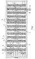
- the machine comprises a machine frame 1, which supports a conveyor device 2.
- the conveyor 2 is designed as an endless chain conveyor and comprises relative to the outside Conveyor chains 3.4 swivel and in two different Swivel positions lockable bottle carrier 5, each of a number of Bottle holders 7 arranged next to one another transversely to the transport direction 6 exhibit.
- the bottle carrier 5 form a cross substantially over the Width of the conveyor 2 extending unit and are on the conveyor chains 3,4 are supported successively with equal mutual distances.
- the bottles to be filled are along a straight conveyor track defined by a guide 8 of the machine frame 1 through the machine from a loading station 9 to a discharge station 10 transported, the bottles 11 in rows transverse to the transport direction 6 grouped and spaced regardless of their diameter and centered, with the help of self-aligning gripper parts 12, 13 the bottle holder 7.
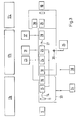
- the loading station 9 is a schematically indicated in the transport direction 6 Subordinate turning device 14 (Fig. 2), in which the upward Bottle opening fed to the loading station 9 and in this position bottles 11 taken over from the bottle holders 7 crosswise in rows a vertical position with the bottle opening pointing downwards by swiveling an entire bottle carrier 5 compared to the conveyor chains supporting these 3,4.
- the transverse rows of bottles now pass initially when conveying at intervals a spray device 15 for the simultaneous introduction of detergent in an upward beam direction into the interior of the Bottles 11 of a transverse row.
- a spray device 15 for the simultaneous introduction of detergent in an upward beam direction into the interior of the Bottles 11 of a transverse row.
- the bottles 11 become inside rinsed out and of any particles contained in them, such as dust particles or the like, cleaned.
- Sterile water is preferably used as the cleaning agent
- the cleaned bottles 11 pass through a first drying device 16, by means of all of the bottles 11 in the drying station located transverse row at the same time left inside the bottles 11 Cleaning agent residues are expelled.
- a drying agent preferably a heated sterile compressed air is used, which is inside the bottle is blown in and under pressure of about 2 to 4 bar, preferably 3 bar, is and a temperature in the range of about 40 ° to 90 ° C, preferably about 60 ° C.
- the compressed air temperature is higher than the load limit temperature for the material of the bottles 11 leads to this not to a thermal impairment of the bottles 11, because of the brevity the pressurized air, the walls of the bottles 11 no temperatures assume that exceed the load limit.
- the bottles 11 are in one non-sterile input and washing area 17a (Fig. 3).
- a spray device 18 forming a sterilization station row of bottles leaving the drying station through an inlet opening 19 into a closed interior 20 of a housing 21 where there is a sterile atmosphere.
- This is made up of sterile air, which is blown under pressure into the interior 20, the entire room occupies and out of the inlet opening 19 and an outlet opening 22nd flows outwards to prevent the entry of air contaminated with germs prevent.
- the sterile air is supplied by a sterile air source 23, to which also the tunnel-like housing 21 defining a sterile area 17b is connected is. However, the latter can also be obtained from an independent sterile air source 25 are supplied with sterile air.
- the interior of the bottles 11 of a row of bottles is simultaneously acted upon by the spray device 18 with a sterilizing agent which is introduced into the inside of the bottle with the jet direction pointing upwards.
- Hydrogen peroxide H 2 O 2
- the sterilizing agent can correspond to the cleaning agent in terms of pressure and temperature.
- the bottles 11 After sterilization, the bottles 11 reach a second one Drying station 24, similar to that in the first drying station 16 with the help of tempered sterile air residues of sterilant from inside the Bottles 11 are expelled.
- the pressure can be between 2 and 4 bar, preferably about 3 bar, and the temperature of the compressed air for the second drying device 24 is between 40 and 90 ° C, preferably about 60 ° C.
- the bottles 11 arrive in a wetting station 26, which, however, is only required or can be operated if a filling material containing CO 2 or N 2 is to be filled into the bottles 11 .
- a wetting station formed by the wetting device 26 all the interiors of the bottles 11 of a transverse row are simultaneously wetted with sterile water, the device being designed similarly to the devices 15 and 18 as a spraying device which enters the sterile water into the interior of the bottle with an upward jet direction from below.
- the bottles 11 reach a second one from the wetting device 26 Turning device 27 in which they are turned again and then with Bottle opening directed above at least approximately vertically aligned are. In this position, the bottles with the liquid contents are preferred Soft drinks, filled, in rows at the same time using a filling device 28
- a closure part (not shown) is supplied.
- the closure part can be, for example Screw cap, as they are for screw caps of the most varied Species is used. It can form a temporary seal, and in a subsequent second closing device 30 can be screwed on the cap of the final closure are formed. Put on and final However, closing can also take place in the first closing device take place, in which case the second closing device 30 is omitted can.
- the bottles 11 leave the Interior 20 of the housing 21 forming the sterile area 17b through the Discharge opening 22. At this point the aseptic filling is complete and contamination of the contents with germs is excluded. Because even after leaving the sterile area 17 b are the bottles 11 until they reach the discharge station 10 in a clean area 17 c, before they are then possibly further via the discharge station 10 Processing stations such as labeling or printing stations, one Packing station etc. are fed.
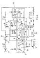
- the Cleaning device 15 and the wetting device 26 preferably from the same source 31 with sterile water formed by sterile condensate can, acted upon, the cleaning agent running off from a bottom part 33 collected and transferred from this to a collector 34 or process becomes.
- the sterile water source 31 can also spray heads 35, 36 of the sterile area 17b of the machine with sterile water when performing CIP cleaning processes supply. They serve during ongoing production Spray heads 35, however, for blowing sterile air into the interior 20 of the Housing 21 to form and maintain the sterile positive pressure atmosphere receive.
- the spray heads 36 are connected to the sterile air source 23 connectable.
- the filling material is fed from a storage container 37, which is also the CIP cleaning can be subjected, as indicated by the Spray head 36 is symbolized.
- the supply of the spray device 18 for the introduction of sterilizing agent takes place from a sterilizing agent source 38, one of which is also Inlet line 39 can be fed in the area of a heat exchanger 40 for heating the sterile air supplied by the source 23 into the Sterile air line empties and enables the sterile air to be sterilized to move. If during a production process or during a CIP cleaning process, the sterile air introduced into the interior 20 with sterilizing agent, a deduction can be made with the sterilizing agent Enriched sterile air can be made via blowers 40, 41 to which a catalyst 42 is connected upstream for separation purposes.
- Sterile water is discharged via a drain line 43, a collector 44 or drain fed according to the collector 34.
- sterile water can also can be removed and fed in the circuit from the interior 20, such as that Circulation line 45 (Fig. 4) reveals.
- the caps either be sterilized as a whole before entering clean area 17c (in which case the closing devices 29 and also 30 in the sterile area 17b could find an arrangement), or they will only be finished in the bottle Sterilized area before placing it, for example by spraying with hot steam, a sterilizing aerosol or the like with the help of a at 46 indicated spray nozzle.
- the second closing device 30 can a suction device 47 may be arranged downstream, which is used on the outside on Vacuum off the closure and any residues of sterilant adhering to the bottle neck, if, for example, with sterile air enriched with sterilizing agents is also used in the clean area 17c.
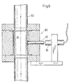
- the drying devices 16, 24 for expelling cleaning or Sterilizing agent residues from the interior of the bottles 11 each include a number of bottles corresponding to the number of bottles in a transverse row Blow lances 50, each at the same time from below in bottles assigned above a transverse row can be inserted and moved out again. This is symbolized by the arrows 51 in FIG. 5.
- the blowing lances 50 comprise in particular an outer tube 52 and an inner tube 53, which are arranged concentrically to each other and at the front end of the blowing lance 50 are interconnected.
- a first outlet opening 54 for drying medium is provided, which through the inner tube 53 is supplied with drying medium through the a separate feed line 55 is fed to the inner tube 53.
- the blowing lances have second outlet openings on their circumference 56, which are connected to a separate second feed line 57, from which they pass through the annular space between the tubes 52, 53 with drying medium be supplied.
- blowing lances 50 In operation, the blowing lances 50, together with their carrier part 58, become one Position in which the ends are below the bottle openings, in an upper end position, in which the front ends of the blowing lances 50 are located near the bottom of the bottle. Once this position is reached drying medium is blown out through the outlet opening 54 and thereby the bottom area of the bottles 11 of cleaning or sterilizing agent residues exempted.
- the drying medium is discharged ended through the outlet opening 54 and drying medium through the Outlet openings 56 blown out, the one after the drying medium Specify the outside and obliquely downward flow direction so that a strong expulsion effect when the downward movement of the blowing lances 50 begins to those still in the area of the bottles 11 which is far from the ground Residual liquid is exercised.
- sensors 60 for checking the loading of the supply lines 55,59 provided with drying medium can have any suitable, known training, but preferably exist from one, an outer part of the outer boundary of the respective supply line 55,57 forming flexible sleeve 61, which is applied on the inside expanded with drying medium and a plunger 62
- Control switch 63 actuated, which causes a fault message when not actuated. This control ensures that each bottle is treated equally becomes.
- the sterilizing agent can be in the spray device 18 with the aid of a spray nozzle are sprayed, as indicated in Fig. 2 and 4. Instead however, there is also the option of using a bottle Wetting mist from sterilizing agent, preferably hydrogen peroxide is used as a sterilizing agent.
- the sterilization effect is here particularly cheap and is based on the fact that the sterilizing agent mist in fine Distribution applied to the entire inner surface of the bottles can be.
- a sterilizing agent mist becomes one Ultrasonic generator 62 generated and in a guided in a line 63, from the sterile air source 23 supplied sterile air flow, which in Working cycle of the spray device 18 is generated and the sterilizing agent mist conveyed into the interior of the bottles 11 in the spray device 18.
- the introduction of the sterilizing agent mist into the interior of the bottles 11 takes place with the help of an injector 64, which is not illustrated by means of an Lift drive, for example a pressure cylinder, in the direction of Arrows 65 vertically from a lower starting position below the trajectory of the bottles 11 into the upper operating position illustrated in FIG. 7 is movable, in which its injection nozzles 66 into the interior of each bottle 11 of a row of bottles in the sterilization position.
- the injection nozzles 66 are each an electrically insulated supported electrode 67 assigned, which is preferably coaxial through the nozzle tube of the injection nozzles 66 extends and protrudes a bit over this.
- Each electrode 67 acts with one of the outside of the bottles 11 in the sterilization position associated counter electrode 68 together to build up an electric field, that between the injection nozzle 66 and the wall of the bottles 11 is effective and causes those electrically charged by the electrode 67 Mist droplets of the sterilizing agent along the field lines Inner wall of the bottles are guided and placed there. For generation of this electric field are electrode 67 and counter electrode 68 to one DC voltage source 69 connected.
- the counter electrode is preferred as in the example illustrated in FIG. 7 designed as a cylinder body, each of a bottle 11 on the outer circumference and surrounds on the ground.
- the counter electrodes are not shown by means of a Drive, for example by means of a pressure medium cylinder, from it shown lowered operating position vertically upwards in a starting position movable in which it is outside the trajectory of the Bottles are located and a retraction of the transverse row to be sterilized enable bottles 11 into the sterilization operating position.
- the counter electrodes 68 simultaneously become vertical lowered into the operating position shown and the injector 64 from its lower starting position into the operating position also shown raised, after which the electric field by connecting the two Electrodes built with the DC voltage source 69 and in synchronism with the Working cycle of the system is a sterile air flow in the to the sterile air source 23 connected line 63 is generated, which in the sterilant fog transported the inside of the bottle.
- the ultrasound generator 62 generating the sterilizing agent mist can be connected to the sterilizing agent source 38 via a ring line 70, can, however, also with a separate sterilization source, not shown are connected on the supply and return sides.
Landscapes
- Engineering & Computer Science (AREA)
- Mechanical Engineering (AREA)
- Filling Of Jars Or Cans And Processes For Cleaning And Sealing Jars (AREA)
- Apparatus For Disinfection Or Sterilisation (AREA)
- Basic Packing Technique (AREA)
Description
- Fig. 1
- eine schematische Draufsicht auf die Fördervorrichtung der Maschine nach der Erfindung,
- Fig. 2
- eine schematische Seitenansicht zu Fig. 1,
- Fig. 3
- ein Fließschema der Handhabungs- und Bearbeitungsvorgänge,
- Fig. 4
- eine schematische, dem Fließschema in Fig. 3 ähnliche Darstellung der Bearbeitungs- und Behandlungsaggregate der Maschine nach der Erfindung,
- Fig. 5
- einen schematischen Querschnitt durch eine Blaslanze,
- Fig. 6
- eine abgebrochene Detaildarstellung einer Trocknungsmittelzuleitung mit Kontrollsensor, und
- Fig. 7
- eine schematische Darstellung, teilweise im Schnitt eines Sterilisationsmittel-Injektors.
Claims (23)
- Verfahren zum Vorbereiten von entlang einer Förderbahn vorbewegten Flaschen (11), insbesondere PET-Flaschen, für eine Befüllung und Befüllen mit einem ein Getränk bildenden Füllgut, bei demdie Flaschen (11) in Reihen quer zur Transportrichtung (6) mit nach oben weisender Flaschenöffnung gruppiert, auf Abstand ausgerichtet und zentriert werden,nach Abschluß der Gruppierung zu Querreihen die Flaschen (11) querreihenweise in eine zumindest annähernd vertikale Stellung mit nach unten weisender Flaschenöffnung geschwenkt werden,die gewendeten Flaschen (11) einer Querreihe gemeinsam innenseitig mit einem Reinigungsmittel gespült werden,in einer ersten Trocknungsstation die Flaschen (11) der gespülten Querreihe innenseitig durch Austreiben von Reinigungsmittelresten getrocknet werden,die Flaschen (11) nach Durchlaufen der ersten Trocknungsstation in eine sterile Umgebung (17b) eingeschleust werden,nach Eintritt einer Flaschenreihe in den Sterilbereich die Flaschen (11) innenseitig mittels eines Sterilisationsmittels sterilisiert werden,in einer nachfolgenden zweiten Trocknungsstation aus den sterilisierten Flaschen (11) Sterilisationsmittelreste ausgetrieben werden,bei vorgesehener Befüllung der Flaschen (11) mit CO2 und/oder N2-haltigem Füllgut die Flaschen (11) nachfolgend innenseitig mit sterilem Wasser benetzt werden,nach dem Trocknen und ggf. Benetzen die Flaschen (11) in einem zweiten Wendevorgang in eine Füllstellung mit nach oben weisender Flaschenöffnung geschwenkt werden,die Flaschen (11) anschließend mit der vorgesehenen Menge an Füllgut befüllt werden,die befüllten Flaschen (11) in einer Verschließstation mit einem Verschlußteil zumindest vorläufig verschlossen werden, unddie verschlossenen Flaschen (11) aus dem Sterilbereich (17b) ausgeschleust werden.
- Verfahren nach Anspruch 1, dadurch gekennzeichnet, daß die Flaschen (11) mit einem flüssigen, unter Druck von etwa 2 bis 4 bar, vorzugsweise etwa 3 bar, stehenden, auf eine Temperatur von etwa 40 bis 90°C, vorzugsweise etwa 45°C, erwärmten Reinigungsmittel bearbeitet werden.
- Verfahren nach Anspruch 1 oder 2, dadurch gekennzeichnet , daß die Flaschen (11) in ihrem Innenraum mit einem Nebel aus Sterilisationsmittel beaufschlagt und die Nebeltröpfchen elektrostatisch auf der Innenwandfläche aufgebracht werden.
- Verfahren nach Anspruch 3, dadurch gekennzeichnet, daß der Sterilisationsmittelnebel durch Ultraschall erzeugt und mittels Sterilluft in das Innere der Flaschen injiziert wird.
- Verfahren nach einem der Ansprüche 1 bis 4, dadurch gekennzeichnet, daß in den beiden Trocknungsstationen Reinigungs- bzw. Sterilisationsmittelreste aus den Flaschen (11) durch Einblasen eines gasförmigen, auf eine Temperatur von etwa 40 bis 90°C, vorzugsweise etwa 60°C, erwärmten und unter Druck von etwa 2 bis 4 bar, vorzugsweise etwa 3 bar, stehenden Trocknungsmediums, vorzugsweise Sterilluft, aus dem Flascheninneren ausgetrieben werden.
- Verfahren nach einem der Ansprüche 1 bis 5, dadurch gekennzeichnet, daß zur Sterilisierung der Flaschen (11) ein vorgewärmtes, unter Druck stehendes, flüssiges Sterilisierungsmittel verwendet wird.
- Verfahren nach Anspruch 6, dadurch gekennzeichnet, daß der Druck des Sterilisierungsmittels etwa 2 bis 4 bar, vorzugsweise etwa 3 bar, und die Temperatur etwa 40 bis 90°C, vorzugsweise etwa 45°C, beträgt.
- Verfahren nach einem der Ansprüche 1 bis 7, dadurch gekennzeichnet , daß das sterile Wasser für die Flaschenbenetzung eine erhöhte Temperatur, vorzugsweise etwa 30 bis 60°C, aufweist.
- Verfahren nach einem der Ansprüche 1 bis 8, dadurch gekennzeichnet, daß die Flaschen (11) in einer intervallförmigen Förderbewegung durch die Maschine transportiert werden.
- Maschine zum Vorbereiten von Flaschen, insbesondere PET-Flaschen, für eine Befüllung und Befüllen mit einem ein Getränk bildenden Füllgut, miteiner die Flaschen entlang einer geraden Förderbahn durch die Maschine von einer Beladestation (9) zu einer Austragstation (10) transportierenden Fördervorrichtung (2), die eine Anzahl von in Querreihen gruppierten Flaschenhaltern (7) mit selbstausrichtenden und -zentrierenden Greiferteilen (12,13) aufweist,mit einer ersten Wendevorrichtung (14) zum gemeinsamen Wenden der Flaschenhalter (7) einer Querreihe von Flaschen (11),einer Sprühvorrichtung (15) zum gleichzeitigen Einbringen von Reinigungsmittel aufwärts in den Innenraum der Flaschen (11) einer Querreihe,einer ersten Trocknungsvorrichtung (16) zum gleichzeitigen Austreiben von Reinigungsmittelresten aus gereinigten Flaschen einer Querreihe mittels eines gasförmigen Trocknungsmediums,einer Vorrichtung (18) zum gleichzeitigen Einbringen eines Sterilisationsmittels in den Innenraum getrockneter Flaschen (11) einer Querreihe,einer zweiten Trocknungsvorrichtung (24) zum gleichzeitigen Austreiben von Sterilisationsmittelresten aus sterilisierten Flaschen (11) einer Querreihe mittels eines gasförmigen Trocknungsmediums,einer Vorrichtung (26) zum gleichzeitigen Benetzen des Innenraums der getrockneten Flaschen (11) einer Querreihe mit sterilem Wasser,einer zweiten Wendevorrichtung (27) zum gemeinsamen Wenden der Flaschenhalter (7) einer Querreihe von Flaschen (11),einer Füllvorrichtung (28) für das gleichzeitige Befüllen einer Querreihe von Flaschen (11) mit Füllgut,einer Verschließvorrichtung (29) zu einem zumindest vorläufigen Verschließen der befüllten Flaschen (11) einer Querreihe durch Zuführen eines Verschlußteils zu jeder Flasche (11), undeinem einen Steriltunnel bildenden Gehäuse (21) mit einer der Sterilisationsvorrichtung (18) vorgeordneten Einschleus- (19) und einer der Verschließvorrichtung (29) nachgeordneten Ausschleusöffnung (22) mit einem Anschluß an eine den Innenraum des Gehäuses (21) mit Überdruck beaufschlagenden Sterilluftquelle (23) bzw. (25).
- Maschine nach Anspruch 10, dadurch gekennzeichnet, daß die Fördervorrichtung (2) als endloser Kettenförderer ausgebildet ist und relativ zu außenseitigen Förderketten (3,4) schwenk- und in zwei unterschiedlichen Schwenkstellungen arretierbare Flaschenträger (5) umfaßt, die jeweils eine Anzahl von quer zur Förderrichtung (6) nebeneinander angeordneten Flaschenhaltern (7) aufweisen, sich quer im wesentlichen über die Breite der Fördervorrichtung (2) erstrecken und in Förderrichtung (6) mit gleichen Abständen aufeinanderfolgend an den Förderketten (3,4) abgestützt sind.
- Maschine nach Anspruch 10 oder 11, dadurch gekennzeichnet, daß die Vorrichtung (18) zum Einbringen eines Sterilisationsmittels einen Ultraschallgenerator (62) zur Ultraschallvernebelung des Sterilisationsmittels und einen an eine Sterilluftquelle (23) angeschlossenen Injektor (64) mit Injektionsdüsen (66) für ein Einblasen von vernebeltem Sterilisationsmittel mittels Sterilluft in den Innenraum der Flaschen (11) umfaßt.
- Maschine nach Anspruch 12, dadurch gekennzeichnet, daß den Injektionsdüsen (66) eine elektrisch isoliert abgestützte Elektrode (67) und der Außenseite der in Sterilisationsstellung befindlichen Flaschen (11) Gegenelektroden (68) zugeordnet sind, zwischen denen ein das Aufbringen der Nebeltröpfchen des Sterilisationsmittels auf der Innenfläche der Flaschen (11) förderndes elektrisches Feld aufbaubar ist.
- Maschine nach Anspruch 13, dadurch gekennzeichnet, daß die den Injektionsdüsen (66) zugeordneten Elektroden (67) als zentrisch in den Düsen angeordnete Stabelektroden ausgebildet sind und den Flaschen (11) jeweils eine zylindrische Gegenelektrode zugeordnet ist, und die Injektionsdüsen (66) und die Gegenelektroden (68) aus einer Ausgangsstellung außerhalb der Flaschenbewegungsbahn in eine den Flaschen (11) jeweils zugeordnete Betriebsstellung und umgekehrt beweglich sind.
- Maschine nach einem der Ansprüche 10 bis 14, dadurch gekennzeichnet, daß die Trocknungsvorrichtungen (16,24) zum Austreiben von Reinigungs- bzw. Sterilisationsmittelresten aus dem Innenraum der Flaschen (11) eine der Anzahl der Flaschen (11) einer Querreihe entsprechende Anzahl von Blaslanzen (50)umfassen, die jeweils gleichzeitig von unten in oberhalb zugeordnete Flaschen (11) einer Querreihe einführ- und aus diesen wieder herausbewegbar sind.
- Maschine nach Anspruch 15, dadurch gekennzeichnet, daß die Blaslanzen (50) bis dicht an den Flaschenboden heranführbar sind und an ihrem dem Flaschenboden gegenüberliegenden Stirnende eine erste Austrittsöffnung (54) für Trocknungsmedium aufweisen, die von einer ersten Zuleitung (55) her mit Trocknungsmedium beaufschlagbar ist, und daß die Blaslanzen (50) nahe ihrem Stirnende an ihrem Umfang mit zweiten Austrittsöffnungen (56) versehen sind, die an eine gesonderte zweite Zuleitung (57) für Trocknungsmedium angeschlossen sind.
- Maschinen nach Anspruch 16, dadurch gekennzeichnet, daß die umfangsseitigen zweiten Austrittsöffnungen (57) dem Trocknungsmedium eine nach außen und schräg abwärts verlaufende Strömungsrichtung vorgeben.
- Maschine nach einem der Ansprüche 15 bis 17, dadurch gekennzeichnet, daß die jeweils in einer Trocknungsvorrichtung (16;24) befindlichen Flaschen (11) mit ihrer Flaschenöffnung einem Leitorgan (59) gegenüberliegen, das dem um die Blaslanze (50) herum aus der Flaschenöffnung austretenden Trocknungsmedium eine zum Flaschenhals hin zurückgerichtete Strömungsrichtung aufprägt.
- Maschine nach einem der Ansprüche 16 bis 18, dadurch gekennzeichnet , daß die Zuleitungen (55,57) zu den ersten und zweiten Austrittsöffnungen (54,56) mittels gesonderter Ventile unabhängig voneinander beaufschlagbar sind.
- Maschine nach einem der Ansprüche 15 bis 19, dadurch gekennzeichnet, daß die Blaslanzen (50) an ihrer Basis von einer Absaugvorrichtung (58', 58") umgeben sind, die in der oberen Endstellung der Blaslanzen der zugeordneten Flaschenöffnung nahe gegenüberliegt.
- Maschine nach einem der Ansprüche 10 bis 20, dadurch gekennzeichnet, daß in den Zuleitungen (55,57) zu den Austrittsöffnungen (54,56) für Trocknungsmedium jeweils ein Sensor (60) zur Kontrolle der Beaufschlagung der Zuleitungen mit Druckmedium zugeordnet ist.
- Maschine nach Anspruch 21, dadurch gekennzeichnet, daß der Sensor eine einen Teil der Außenbegrenzung seiner Zuleitung bildende, flexible Manschette aufweist, die bei innenseitiger Beaufschlagung mit Trocknungsmedium expandiert und einen Kontrollschalter betätigt.
- Maschine nach einem der Ansprüche 10 bis 22, dadurch gekennzeichnet, daß der Sterilisationsstation zwei Trocknungsvorrichtungen mit zwei Blaslanzengruppen nachgeordnet sind.
Applications Claiming Priority (3)
| Application Number | Priority Date | Filing Date | Title |
|---|---|---|---|
| DE19700156 | 1997-01-07 | ||
| DE19700156 | 1997-01-07 | ||
| PCT/EP1998/000028 WO1998030491A1 (de) | 1997-01-07 | 1998-01-05 | Verfahren und maschine zum vorbereiten von flaschen für eine befüllung und befüllen der flaschen |
Publications (2)
| Publication Number | Publication Date |
|---|---|
| EP0951437A1 EP0951437A1 (de) | 1999-10-27 |
| EP0951437B1 true EP0951437B1 (de) | 2001-04-04 |
Family
ID=7816833
Family Applications (1)
| Application Number | Title | Priority Date | Filing Date |
|---|---|---|---|
| EP98902978A Expired - Lifetime EP0951437B1 (de) | 1997-01-07 | 1998-01-05 | Verfahren und maschine zum vorbereiten von flaschen für eine befüllung und befüllen der flaschen |
Country Status (12)
| Country | Link |
|---|---|
| US (1) | US6328928B1 (de) |
| EP (1) | EP0951437B1 (de) |
| JP (1) | JP2001507659A (de) |
| AR (1) | AR011063A1 (de) |
| AT (1) | ATE200269T1 (de) |
| BR (1) | BR9806850A (de) |
| DE (1) | DE59800588D1 (de) |
| DK (1) | DK0951437T3 (de) |
| ES (1) | ES2158667T3 (de) |
| GR (1) | GR3036026T3 (de) |
| PT (1) | PT951437E (de) |
| WO (1) | WO1998030491A1 (de) |
Cited By (1)
| Publication number | Priority date | Publication date | Assignee | Title |
|---|---|---|---|---|
| US11147894B2 (en) | 2007-11-19 | 2021-10-19 | Sidel Participations | Device for transporting a hollow body, installation provided with such devices, and method for conveying a hollow body attached to such a device |
Families Citing this family (42)
| Publication number | Priority date | Publication date | Assignee | Title |
|---|---|---|---|---|
| WO2001017891A1 (de) * | 1999-09-07 | 2001-03-15 | Alcoa Deutschland Gmbh | Vorrichtung und verfahren zum sterilen befüllen von behältern |
| DE19949692A1 (de) * | 1999-10-15 | 2001-04-19 | Gea Finnah Gmbh | Verfahren zur Sterilisation von PET-Flaschen |
| DE10016631A1 (de) * | 2000-04-04 | 2001-10-11 | Tetra Laval Holdings & Finance | Fördervorrichtung mit Packungsträger |
| FR2814095A1 (fr) * | 2000-09-18 | 2002-03-22 | Jean Paul Stentz | Procede de sterilisation de bouteilles et machine mettant en oeuvre ledit procede |
| US20020085971A1 (en) * | 2001-01-03 | 2002-07-04 | Raniwala Subodh K. | Bottle sterilizing system and method |
| EP1384670A4 (de) * | 2001-05-01 | 2007-04-11 | Toyo Seikan Kaisha Ltd | Verfahren und system zum sterilisieren eines lebensmittelverpackungsbehälters oder lebensmittelfüllsystem |
| US6986910B2 (en) | 2001-06-28 | 2006-01-17 | Albemarle Corporation | Microbiological control in poultry processing |
| DE10140807A1 (de) * | 2001-08-15 | 2003-02-27 | Ruediger Haaga Gmbh | Maschinenanlage zum Sterilisieren und Befüllen von Behältern |
| JP4526820B2 (ja) * | 2001-09-05 | 2010-08-18 | 大日本印刷株式会社 | Petボトルの殺菌方法及び殺菌装置 |
| US20050226796A1 (en) * | 2002-02-12 | 2005-10-13 | Atsushi Hayakawa | Method of sterilization for container, apparatus using therefor, and heat treatment for container |
| ES2211285B1 (es) * | 2002-05-16 | 2005-03-16 | Sociedad Española De Carburos Metalicos, S.A. | Procedimiento e instalacion para el llenado de botellas con gas. |
| KR100443797B1 (ko) * | 2002-09-28 | 2004-08-11 | 전철수 | 재활용공병세척시스템 |
| SE524497C2 (sv) * | 2002-12-13 | 2004-08-17 | Tetra Laval Holdings & Finance | Steriliseringsanordning |
| AU2004100000A4 (en) | 2004-01-02 | 2004-02-12 | Sands Innovations Pty Ltd | Dispensing stirring implement |
| EP1607634A2 (de) * | 2004-06-17 | 2005-12-21 | Jesper Andersen | System um einen eine viskos Flüssigkeit enthaltenden Behälter vollständig zu entleeren |
| ITBO20040626A1 (it) * | 2004-10-13 | 2005-01-13 | Marchesini Group Spa | Macchina per il confezionamento di prodotti in ambiente protetto |
| DE202005022086U1 (de) | 2005-07-08 | 2013-06-27 | Khs Corpoplast Gmbh | Vorrichtung zum Verschließen von Flaschen mit sterilen Kappen |
| DE102005032322A1 (de) * | 2005-07-08 | 2007-01-11 | Sig Technology Ag | Verfahren und Maschine zum Verschließen von Flaschen mit sterilen Kappen |
| DE102006038255B4 (de) * | 2006-08-16 | 2008-07-10 | Khs Ag | Verfahren und Vorrichtung zum Behandeln von Behältern |
| WO2008092200A1 (en) | 2007-01-31 | 2008-08-07 | Sands Innovations Pty Ltd | A dispensing utensil and manufacturing method therefor |
| WO2009031436A1 (ja) * | 2007-09-03 | 2009-03-12 | Dai Nippon Printing Co., Ltd. | 包装体とその製造方法及び装置 |
| DE102008022708A1 (de) * | 2008-05-07 | 2009-11-12 | Khs Ag | Verfahren sowie Verschlussvorrichtung zum Verschließen von Dosen oder dergleichen Behältern sowie Packmittel |
| WO2010065980A1 (en) | 2008-12-09 | 2010-06-17 | Sands Innovations Pty Ltd | A dispensing container |
| USD636890S1 (en) | 2009-09-17 | 2011-04-26 | Sands Innovations Pty. Ltd. | Dispensing utensil |
| WO2011072628A1 (de) * | 2009-12-14 | 2011-06-23 | Hamba Filltec Gmbh & Co. Kg | Vorrichtung zum befüllen von behältern |
| US8511500B2 (en) | 2010-06-07 | 2013-08-20 | Sands Innovations Pty. Ltd. | Dispensing container |
| PL2399681T3 (pl) * | 2010-06-25 | 2013-05-31 | R Bardi S R L | Sposób oraz urządzenie do napełniania oraz płukania pojemników oraz zintegrowana instalacja do formowania z rozdmuchem, płukania oraz napełniania pojemników |
| US9120587B2 (en) | 2010-09-10 | 2015-09-01 | Pepsico, Inc. | In-package non-ionizing electromagnetic radiation sterilization |
| US9067773B2 (en) | 2010-09-10 | 2015-06-30 | Pepsico, Inc. | Prevention of agglomeration of particles during sterilization processes |
| US8485360B2 (en) | 2011-03-04 | 2013-07-16 | Sands Innovations Pty, Ltd. | Fracturable container |
| US9173248B2 (en) * | 2011-03-14 | 2015-10-27 | Products Support, Inc. | Thawing oven |
| CN103917453B (zh) * | 2011-10-25 | 2016-03-23 | 大日本印刷株式会社 | 饮料填充方法及其装置 |
| DE102012206297A1 (de) * | 2012-04-17 | 2013-10-17 | Krones Ag | Verfahren und Vorrichtung zur Dosenherstellung und Dosenabfüllung |
| CN103641054B (zh) * | 2013-12-05 | 2016-01-20 | 镇江市顶智微电子科技有限公司 | 一种输送推进涮洗灌装瓶系统 |
| CN104326431B (zh) * | 2014-11-25 | 2016-07-13 | 镇江市顶智微电子科技有限公司 | 一种灌装瓶纠正推挤涮洗输送灌装运盖旋盖贴标打码系统 |
| EP3227226B1 (de) * | 2014-12-01 | 2020-01-08 | Gea Procomac S.p.A. | Verfahren und vorrichtung zum schliessen von behältern |
| CN105129705A (zh) * | 2015-07-24 | 2015-12-09 | 镇江市顶智微电子科技有限公司 | 一种医药化学生物试剂瓶涮洗筛选输送运盖灌装封口贴标签方法 |
| KR20170054631A (ko) * | 2015-11-09 | 2017-05-18 | 삼성전자주식회사 | 수분 검사 장치 |
| WO2017186732A2 (en) * | 2016-04-27 | 2017-11-02 | Tetra Laval Holdings & Finance S.A. | A device, system and method for evacuating a sterilization agent for sterilizing a package at a sterilization chamber |
| EP3757024A1 (de) * | 2019-06-25 | 2020-12-30 | Andreas Kunzmann | Anlage zum befüllen und verschliessen von dosen unter hygienischen bedingungen |
| CN110762956B (zh) * | 2019-10-31 | 2020-07-03 | 四川康特能药业有限公司 | 一种去感热口服液药瓶干燥箱以及装药加塞装置 |
| DE102019130364A1 (de) * | 2019-11-11 | 2021-05-12 | Khs Gmbh | Lineare Füllmaschine zum Befüllen von Behältern mit Füllgut |
Family Cites Families (12)
| Publication number | Priority date | Publication date | Assignee | Title |
|---|---|---|---|---|
| NL6500035A (de) * | 1965-01-05 | 1965-08-25 | ||
| US3575713A (en) * | 1969-07-31 | 1971-04-20 | Owens Illinois Inc | Method and apparatus for cleaning containers |
| US4296068A (en) * | 1979-02-19 | 1981-10-20 | Dai Nippon Insatsu Kabushiki Kaisha | Apparatus for sterilizing a succession of food containers or the like |
| BE894957A (fr) * | 1981-11-14 | 1983-03-01 | Jagenberg Ag | Procede et dispositif pour la sterilisation d'un materiel, d'emballage, en particulier, de recipients d'emballage |
| FR2543126B3 (fr) * | 1983-03-24 | 1986-01-03 | Volvic Eaux | Procede de remplissage aseptique, a froid, de recipients, en particulier en matiere synthetique - bouteilles ou analogues - par des boissons, notamment a base de jus de fruits |
| DE3414268A1 (de) * | 1984-04-14 | 1985-10-24 | Kolbus Gmbh & Co Kg | Verfahren und vorrichtung zum entkeimen von lebensmittelbehaeltern |
| DE3522996A1 (de) * | 1985-06-27 | 1987-01-08 | Kolbus Gmbh & Co Kg | Verfahren zur abgrenzung steriler raeume gegen austreten von toxischen sterilisationsmitteln oder eindringen von mikroorganismen, vorzugsweise in anwendung fuer fuellmaschinen, und vorrichtung zur durchfuehrung des verfahrens |
| DE3644486A1 (de) * | 1986-12-24 | 1988-07-07 | Kolbus Gmbh & Co Kg | Vorrichtung zum entkeimen von lebensmittelbehaeltern |
| DE3701915A1 (de) * | 1987-01-23 | 1988-08-04 | Finnah Gmbh | Verfahren und maschine zur sterilverpackung von fuellguetern in behaeltern |
| US4934392A (en) * | 1987-11-20 | 1990-06-19 | Shubert Systems Limited | Cleaning apparatus |
| DE4332241A1 (de) * | 1993-09-23 | 1995-03-30 | Kronseder Maschf Krones | Verfahren zum Behandeln von Flaschen o. dgl. |
| US5792435A (en) * | 1997-04-08 | 1998-08-11 | Steris Corporation | Vapor phase decontaminant isolator apparatus with integral vapor phase decontaminant generator system |
-
1998
- 1998-01-05 AT AT98902978T patent/ATE200269T1/de not_active IP Right Cessation
- 1998-01-05 DK DK98902978T patent/DK0951437T3/da active
- 1998-01-05 BR BR9806850-4A patent/BR9806850A/pt not_active Application Discontinuation
- 1998-01-05 EP EP98902978A patent/EP0951437B1/de not_active Expired - Lifetime
- 1998-01-05 JP JP53052898A patent/JP2001507659A/ja active Pending
- 1998-01-05 DE DE59800588T patent/DE59800588D1/de not_active Expired - Lifetime
- 1998-01-05 ES ES98902978T patent/ES2158667T3/es not_active Expired - Lifetime
- 1998-01-05 WO PCT/EP1998/000028 patent/WO1998030491A1/de not_active Ceased
- 1998-01-05 PT PT98902978T patent/PT951437E/pt unknown
- 1998-01-07 AR ARP980100073A patent/AR011063A1/es unknown
-
1999
- 1999-03-03 US US09/254,296 patent/US6328928B1/en not_active Expired - Lifetime
-
2001
- 2001-06-13 GR GR20010400879T patent/GR3036026T3/el not_active IP Right Cessation
Cited By (1)
| Publication number | Priority date | Publication date | Assignee | Title |
|---|---|---|---|---|
| US11147894B2 (en) | 2007-11-19 | 2021-10-19 | Sidel Participations | Device for transporting a hollow body, installation provided with such devices, and method for conveying a hollow body attached to such a device |
Also Published As
| Publication number | Publication date |
|---|---|
| BR9806850A (pt) | 2000-03-14 |
| US6328928B1 (en) | 2001-12-11 |
| ATE200269T1 (de) | 2001-04-15 |
| ES2158667T3 (es) | 2001-09-01 |
| DK0951437T3 (da) | 2001-08-13 |
| GR3036026T3 (en) | 2001-09-28 |
| DE59800588D1 (de) | 2001-05-10 |
| WO1998030491A1 (de) | 1998-07-16 |
| AR011063A1 (es) | 2000-08-02 |
| JP2001507659A (ja) | 2001-06-12 |
| EP0951437A1 (de) | 1999-10-27 |
| PT951437E (pt) | 2001-09-28 |
Similar Documents
| Publication | Publication Date | Title |
|---|---|---|
| EP0951437B1 (de) | Verfahren und maschine zum vorbereiten von flaschen für eine befüllung und befüllen der flaschen | |
| EP2349354B1 (de) | Verfahren zur vorbehandlung von vorformlingen und streckblasmaschine zur vorbehandlung und zum streckblasen von vorformlingen zu behältern | |
| EP0932577B1 (de) | Verfahren und vorrichtung zum sterilisieren und befüllen von verpackungsbehältern | |
| EP1741666B1 (de) | Verfahren und Maschine zum Verschliessen von Flaschen mit sterilen Kappen | |
| EP0993418B1 (de) | Verfahren und anlage zum verschliessen von flaschen mit sterilen verschlusskappen | |
| EP2086869B1 (de) | Vorrichtung und verfahren zur herstellung von kunststoffbehältern | |
| EP2295324B1 (de) | Verfahren und Vorrichtung zum Streckblasformen oder Blasformen und Füllen steriler Behälter | |
| DE102004026565B4 (de) | Verfahren zum Reinigen von Flaschen o.dgl. Behälter sowie Reinigungsmaschine | |
| DE102009033809A1 (de) | Vorrichtung zum Behandeln von Behältnissen mit Trägersterilisation | |
| EP0479010B1 (de) | Vorrichtung und Verfahren zum Sterilisieren, Füllen und Verschliessen einer Füllöffnung | |
| DE102010045832B4 (de) | Aseptik Sterilisationseinheit für Reinraum auf Blasrad | |
| EP0381841A1 (de) | Verfahren und Vorrichtung zum Reinigen und Sterilisieren von Behältern | |
| EP1220787B1 (de) | Verfahren zur sterilisation von pet-flaschen | |
| EP2537662B1 (de) | Vorrichtung und Verfahren zum Umformen von Kunststoffvorformlingen zu Kunststoffbehältnissen mit abgedichteter Reckstangenbewegung | |
| WO2021121747A1 (de) | Vorrichtung zur herstellung und behandlung von kunststoffbehältern | |
| EP2420258B1 (de) | Vorrichtung zum Behandeln von Verpackungen | |
| EP4008364B1 (de) | Vorrichtung und verfahren zum sterilisieren von kunststoffvorformlingen | |
| EP2537663B1 (de) | Vorrichtung und Verfahren zum Umformen von Kunststoffvorformlingen zu Kunststoffbehältnissen mit durch ein Wasserschloss geführter Luftabsaugung | |
| DE4218941A1 (de) | Vorrichtung zum Sterilisieren von Verpackungsbehältern | |
| WO2014124738A1 (de) | Verfahren zum verpacken von flüssigen produkten unter druck in flaschen aus kunststoff oder dgl. behälter | |
| DE102019133131A1 (de) | Getränke-Abfüllanlage | |
| WO2006053745A1 (de) | Verfahren und vorrichtung zum sterilisieren kontinuierlich bewegter kunststoffflaschen | |
| DE3701079A1 (de) | Verfahren zum entkeimen von verpackungsbehaeltern | |
| EP3978223B1 (de) | Vorrichtung und verfahren zum behandeln von behältnissen mit beaufschlagung durch ionisierte luft | |
| EP4703274A2 (de) | Behälterbehandlungsanlage und verfahren zum betrieb einer behälterbehandlungsanlage |
Legal Events
| Date | Code | Title | Description |
|---|---|---|---|
| PUAI | Public reference made under article 153(3) epc to a published international application that has entered the european phase |
Free format text: ORIGINAL CODE: 0009012 |
|
| 17P | Request for examination filed |
Effective date: 19990414 |
|
| AK | Designated contracting states |
Kind code of ref document: A1 Designated state(s): AT BE CH DE DK ES FI FR GB GR IE IT LI LU MC NL PT SE |
|
| GRAG | Despatch of communication of intention to grant |
Free format text: ORIGINAL CODE: EPIDOS AGRA |
|
| GRAG | Despatch of communication of intention to grant |
Free format text: ORIGINAL CODE: EPIDOS AGRA |
|
| GRAH | Despatch of communication of intention to grant a patent |
Free format text: ORIGINAL CODE: EPIDOS IGRA |
|
| 17Q | First examination report despatched |
Effective date: 20000517 |
|
| GRAH | Despatch of communication of intention to grant a patent |
Free format text: ORIGINAL CODE: EPIDOS IGRA |
|
| GRAA | (expected) grant |
Free format text: ORIGINAL CODE: 0009210 |
|
| AK | Designated contracting states |
Kind code of ref document: B1 Designated state(s): AT BE CH DE DK ES FI FR GB GR IE IT LI LU MC NL PT SE |
|
| REF | Corresponds to: |
Ref document number: 200269 Country of ref document: AT Date of ref document: 20010415 Kind code of ref document: T |
|
| REG | Reference to a national code |
Ref country code: CH Ref legal event code: EP |
|
| REG | Reference to a national code |
Ref country code: IE Ref legal event code: FG4D Free format text: GERMAN |
|
| REF | Corresponds to: |
Ref document number: 59800588 Country of ref document: DE Date of ref document: 20010510 |
|
| REG | Reference to a national code |
Ref country code: CH Ref legal event code: NV Representative=s name: PATENTANWALTSBUERO FELDMANN AG |
|
| ITF | It: translation for a ep patent filed | ||
| ET | Fr: translation filed | ||
| GBT | Gb: translation of ep patent filed (gb section 77(6)(a)/1977) |
Effective date: 20010618 |
|
| REG | Reference to a national code |
Ref country code: DK Ref legal event code: T3 |
|
| REG | Reference to a national code |
Ref country code: ES Ref legal event code: FG2A Ref document number: 2158667 Country of ref document: ES Kind code of ref document: T3 |
|
| REG | Reference to a national code |
Ref country code: PT Ref legal event code: SC4A Free format text: AVAILABILITY OF NATIONAL TRANSLATION Effective date: 20010626 |
|
| REG | Reference to a national code |
Ref country code: GB Ref legal event code: IF02 |
|
| PLBE | No opposition filed within time limit |
Free format text: ORIGINAL CODE: 0009261 |
|
| STAA | Information on the status of an ep patent application or granted ep patent |
Free format text: STATUS: NO OPPOSITION FILED WITHIN TIME LIMIT |
|
| 26N | No opposition filed | ||
| PG25 | Lapsed in a contracting state [announced via postgrant information from national office to epo] |
Ref country code: MC Free format text: LAPSE BECAUSE OF NON-PAYMENT OF DUE FEES Effective date: 20020801 |
|
| PGFP | Annual fee paid to national office [announced via postgrant information from national office to epo] |
Ref country code: SE Payment date: 20021122 Year of fee payment: 6 |
|
| PGFP | Annual fee paid to national office [announced via postgrant information from national office to epo] |
Ref country code: GR Payment date: 20021206 Year of fee payment: 6 |
|
| PGFP | Annual fee paid to national office [announced via postgrant information from national office to epo] |
Ref country code: IE Payment date: 20021217 Year of fee payment: 6 |
|
| PGFP | Annual fee paid to national office [announced via postgrant information from national office to epo] |
Ref country code: PT Payment date: 20021219 Year of fee payment: 6 |
|
| PGFP | Annual fee paid to national office [announced via postgrant information from national office to epo] |
Ref country code: FR Payment date: 20021230 Year of fee payment: 6 |
|
| PGFP | Annual fee paid to national office [announced via postgrant information from national office to epo] |
Ref country code: BE Payment date: 20030102 Year of fee payment: 6 |
|
| PGFP | Annual fee paid to national office [announced via postgrant information from national office to epo] |
Ref country code: GB Payment date: 20030107 Year of fee payment: 6 Ref country code: DK Payment date: 20030107 Year of fee payment: 6 |
|
| PGFP | Annual fee paid to national office [announced via postgrant information from national office to epo] |
Ref country code: LU Payment date: 20030116 Year of fee payment: 6 |
|
| PGFP | Annual fee paid to national office [announced via postgrant information from national office to epo] |
Ref country code: ES Payment date: 20030124 Year of fee payment: 6 |
|
| PGFP | Annual fee paid to national office [announced via postgrant information from national office to epo] |
Ref country code: AT Payment date: 20030127 Year of fee payment: 6 Ref country code: FI Payment date: 20030127 Year of fee payment: 6 |
|
| PGFP | Annual fee paid to national office [announced via postgrant information from national office to epo] |
Ref country code: NL Payment date: 20030228 Year of fee payment: 6 |
|
| PGFP | Annual fee paid to national office [announced via postgrant information from national office to epo] |
Ref country code: CH Payment date: 20030429 Year of fee payment: 6 |
|
| PG25 | Lapsed in a contracting state [announced via postgrant information from national office to epo] |
Ref country code: LU Free format text: LAPSE BECAUSE OF NON-PAYMENT OF DUE FEES Effective date: 20040105 Ref country code: IE Free format text: LAPSE BECAUSE OF NON-PAYMENT OF DUE FEES Effective date: 20040105 Ref country code: GB Free format text: LAPSE BECAUSE OF NON-PAYMENT OF DUE FEES Effective date: 20040105 Ref country code: FI Free format text: LAPSE BECAUSE OF NON-PAYMENT OF DUE FEES Effective date: 20040105 Ref country code: AT Free format text: LAPSE BECAUSE OF NON-PAYMENT OF DUE FEES Effective date: 20040105 |
|
| PG25 | Lapsed in a contracting state [announced via postgrant information from national office to epo] |
Ref country code: SE Free format text: LAPSE BECAUSE OF NON-PAYMENT OF DUE FEES Effective date: 20040106 |
|
| PG25 | Lapsed in a contracting state [announced via postgrant information from national office to epo] |
Ref country code: ES Free format text: LAPSE BECAUSE OF NON-PAYMENT OF DUE FEES Effective date: 20040107 |
|
| PG25 | Lapsed in a contracting state [announced via postgrant information from national office to epo] |
Ref country code: LI Free format text: LAPSE BECAUSE OF NON-PAYMENT OF DUE FEES Effective date: 20040131 Ref country code: CH Free format text: LAPSE BECAUSE OF NON-PAYMENT OF DUE FEES Effective date: 20040131 Ref country code: BE Free format text: LAPSE BECAUSE OF NON-PAYMENT OF DUE FEES Effective date: 20040131 |
|
| PG25 | Lapsed in a contracting state [announced via postgrant information from national office to epo] |
Ref country code: DK Free format text: LAPSE BECAUSE OF NON-PAYMENT OF DUE FEES Effective date: 20040202 |
|
| BERE | Be: lapsed |
Owner name: *GEA FINNAH G.M.B.H. Effective date: 20040131 |
|
| PG25 | Lapsed in a contracting state [announced via postgrant information from national office to epo] |
Ref country code: PT Free format text: LAPSE BECAUSE OF NON-PAYMENT OF DUE FEES Effective date: 20040731 |
|
| PG25 | Lapsed in a contracting state [announced via postgrant information from national office to epo] |
Ref country code: NL Free format text: LAPSE BECAUSE OF NON-PAYMENT OF DUE FEES Effective date: 20040801 |
|
| PG25 | Lapsed in a contracting state [announced via postgrant information from national office to epo] |
Ref country code: GR Free format text: LAPSE BECAUSE OF NON-PAYMENT OF DUE FEES Effective date: 20040804 |
|
| GBPC | Gb: european patent ceased through non-payment of renewal fee |
Effective date: 20040105 |
|
| EUG | Se: european patent has lapsed | ||
| REG | Reference to a national code |
Ref country code: DK Ref legal event code: EBP |
|
| REG | Reference to a national code |
Ref country code: CH Ref legal event code: PL |
|
| PG25 | Lapsed in a contracting state [announced via postgrant information from national office to epo] |
Ref country code: FR Free format text: LAPSE BECAUSE OF NON-PAYMENT OF DUE FEES Effective date: 20040930 |
|
| NLV4 | Nl: lapsed or anulled due to non-payment of the annual fee |
Effective date: 20040801 |
|
| REG | Reference to a national code |
Ref country code: IE Ref legal event code: MM4A |
|
| REG | Reference to a national code |
Ref country code: FR Ref legal event code: ST |
|
| REG | Reference to a national code |
Ref country code: FR Ref legal event code: TP Ref country code: FR Ref legal event code: CD Ref country code: FR Ref legal event code: CA |
|
| PG25 | Lapsed in a contracting state [announced via postgrant information from national office to epo] |
Ref country code: IT Free format text: LAPSE BECAUSE OF NON-PAYMENT OF DUE FEES Effective date: 20050105 |
|
| REG | Reference to a national code |
Ref country code: ES Ref legal event code: FD2A Effective date: 20040107 |
|
| PGRI | Patent reinstated in contracting state [announced from national office to epo] |
Ref country code: IT Effective date: 20091201 |
|
| REG | Reference to a national code |
Ref country code: DE Ref legal event code: R081 Ref document number: 59800588 Country of ref document: DE Owner name: KHS CORPOPLAST GMBH, DE Free format text: FORMER OWNER: SIG TECHNOLOGY AG, NEUHAUSEN AM RHEINFALL, CH Effective date: 20110504 |
|
| REG | Reference to a national code |
Ref country code: DE Ref legal event code: R082 Ref document number: 59800588 Country of ref document: DE |
|
| PGFP | Annual fee paid to national office [announced via postgrant information from national office to epo] |
Ref country code: DE Payment date: 20170120 Year of fee payment: 20 |
|
| PGFP | Annual fee paid to national office [announced via postgrant information from national office to epo] |
Ref country code: IT Payment date: 20170124 Year of fee payment: 20 |
|
| REG | Reference to a national code |
Ref country code: DE Ref legal event code: R071 Ref document number: 59800588 Country of ref document: DE |