EP0951849A2 - Einhängesitz zum Einhängen in einen Wandhalter - Google Patents
Einhängesitz zum Einhängen in einen Wandhalter Download PDFInfo
- Publication number
- EP0951849A2 EP0951849A2 EP99106977A EP99106977A EP0951849A2 EP 0951849 A2 EP0951849 A2 EP 0951849A2 EP 99106977 A EP99106977 A EP 99106977A EP 99106977 A EP99106977 A EP 99106977A EP 0951849 A2 EP0951849 A2 EP 0951849A2
- Authority
- EP
- European Patent Office
- Prior art keywords
- seat
- seat according
- hanging
- legs
- carrier
- Prior art date
- Legal status (The legal status is an assumption and is not a legal conclusion. Google has not performed a legal analysis and makes no representation as to the accuracy of the status listed.)
- Granted
Links
Images


Classifications
-
- A—HUMAN NECESSITIES
- A47—FURNITURE; DOMESTIC ARTICLES OR APPLIANCES; COFFEE MILLS; SPICE MILLS; SUCTION CLEANERS IN GENERAL
- A47C—CHAIRS; SOFAS; BEDS
- A47C9/00—Stools for specified purposes
- A47C9/06—Wall stools
-
- A—HUMAN NECESSITIES
- A47—FURNITURE; DOMESTIC ARTICLES OR APPLIANCES; COFFEE MILLS; SPICE MILLS; SUCTION CLEANERS IN GENERAL
- A47K—SANITARY EQUIPMENT; ACCESSORIES THEREFOR, e.g. TOILET ACCESSORIES
- A47K3/00—Baths; Showers; Appurtenances therefor
- A47K3/28—Showers or bathing douches
- A47K3/281—Accessories for showers or bathing douches, e.g. cleaning devices for walls or floors of showers
- A47K3/282—Seats specially adapted for showers
Definitions
- the invention relates to a hanging seat for hanging in a Wall bracket according to the preamble of claim 1.
- the invention has for its object a hanging seat this Type in such a way that those acting on the handle and / or the wall Forces are reduced so that damage to the handle and / or the wall is properly avoided.
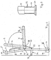
- the hanging seat 1 is mounted on the wall in showers, baths or the like, so that sick, disabled or elderly people can sit while showering.
- the seat 1 has a hanging part 2, 2 in a handle 3, preferably in a cross piece 3 of the U-shaped handle, or hung in a handrail.
- the handle 3 is attached horizontally to a wall 4.
- the seat 1 has a seat part 5 with a peripheral frame 6 and a backrest part 7 with a frame 8. Both parts 5 and 7 are attached to an H-shaped support 9. This has about one centrally located crosspiece 10, two of which are mutually downward parallel legs 11 and 12 and two to each other upwards parallel vertical struts 13 and 14 protrude.
- the pillars 11, 12 run essentially vertically when the seat 1 is mounted, while the struts 13, 14 slightly inclined towards the rear towards the wall 4 are.
- the legs 11, 12 and the struts 13, 14 are preferred formed by pipe sections.
- the struts 13, 14 close via an approximately wedge-shaped intermediate piece 15 to the supporting leg 11 and 12 respectively. That between the pillar 12 and the strut 14th The proposed intermediate piece cannot be seen in the drawing.
- the free ends 17, 18 of the legs 11, 12 are telescopic. They have an inner tube piece 19, 20, which is advantageously screwed into the legs 11, 12, at the free end of which a plate-like end piece 21 or 22 is provided. With the end pieces 21, 22, the support 9 is supported flatly on the floor.
- the pipe sections 19, 20 By rotating the pipe sections 19, 20 in the desired direction, the height of the seat 1 can be adjusted so that the user sits comfortably on the seat surface 5 and the ends 2, 2 ' perfectly position the horizontal crosspiece 3 of the handle 3 overlap.
- set screws can also be provided, which are screwed into the lower end of the legs 12, 13.
- the struts 13, 14 are to form the hook-like suspension parts 2 and 2 turned opposite to wall 4.
- the ends 2, 2 ' protrude through a handle opening 25 of the handle 3 and overlap the crosspiece 3 .
- the seat and backrest parts 5 and 7 can be within their frame 6 or 8 have a padded seat or back part.
- the seat part can also have a hygienic neckline.
- the seat 1 can be easily and quickly attached to the handle 3 with little effort.
- the seat is placed in an inclined position in which its suspension parts 2, 2 come to rest below the handle 3 and in the area of the handle opening 25.
- the seat is pivoted clockwise in the direction of arrow P in FIG. 4, being about the axis of the crosspiece 3 of the handle 3 pivots.
- the hanging parts 2, 2 into the area of the grip opening 25 and slide through it until it reaches the crosspiece 3 spread.
- the seat surface 5 is advantageously folded upwards into a non-use position (FIG. 2, dash-dotted lines).
- the legs 17, 18 can be adjusted so that the seat 5 has the desired seat height.
- the support parts 24 of the legs 11, 12 are retracted or extended as necessary to ensure secure support on the wall 4 in the respective position of the legs. If the seat has the correct position to the floor and to the wall 4, its seat 5 can be pivoted downwards from the position of use out of use into the position of use (solid lines in FIG. 2) in the direction of the arrow P 1 . The seat is now properly aligned with the floor and wall so that it cannot tip and slide.
- the seat 1 When using the seat 1, the forces occurring when sitting, since it stands on the floor with the legs 11, 12, are transmitted directly to the floor, so that no vertical forces act on the handle 3 or the wall 4.
- the seat 1 can also be mounted on partitions or on walls which do not have a particularly high load-bearing capacity. This reliably prevents the risk of damage to the wall and also the risk that the handle 3 will be damaged by the vertical forces that occur.
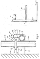
- FIGS. 1 to 4 show a further embodiment of a hanging seat 1a, which is only thereby from the seat 1 according to FIGS. 1 to 4 distinguishes that separately designed clamps as hanging parts 29 are provided which are in an elongated opening 30 straight ends 31 of the struts 13a are attached.
- the clamping brackets 29 have a rod-shaped plug-in part 33 with which they protrude through the opening 30 which extends in the longitudinal direction of the struts 13a of the carrier 9a.
- the plug-in parts 33 have an external thread 34 over almost their entire length, so that a nut 32 can be screwed onto the free end 35 which projects over the strut 13a towards the rear towards the wall 4.
- the other end 36 of the plug-in part 33 has no thread and is perpendicular to a holding part 37 of the clamping bracket 29.
- the holding part 37 is designed as an approximately rectangular plate and has on its inside 37 a transverse groove 38, which is partially circular in cross-section, into which the transverse web 3 when the hanging part 29 is installed of the handle 3 protrudes.
- the transverse groove 38 is designed such that the transverse web 3 ' lies flat against its bottom.
- the plug part end 36 is fastened approximately centrally in the upper half 39 of the holding part 37 in FIGS. 5 and 6.
- the holding part 37 runs perpendicular to the transverse web 3 of the handle 3. In order to reliably prevent the clamping bracket 29 from slipping on the handle 3, the nut 32 is pulled so firmly against the strut 13a that a firm bracing of the clamping bracket 29 on the handle 3 is ensured.
- the seat 1a is first brought into an oblique position with respect to the wall 4, as shown in FIG. 4.
- the lower end 17a of the supporting leg 11a is retracted so that the upper free end 31 of the strut 13a can be easily inserted into the handle opening from below.
- the seat is then pivoted in the direction of the wall 4 until it is properly supported on it with its support part 24a.
- the end of the leg 17a may be extended correspondingly to ensure proper support on the floor.
- the clamping part 29 with its plug-in part 33 is inserted through the slot opening 30, which lies essentially in the area above the handle 3.
- the clamping part 29 is then aligned so that the crossbar 3rd of the handle 3 lies in the transverse groove 38 of the holding part 37. In this position, the nut 32 is screwed onto the protruding plug end 33. The struts 13a are pulled firmly against the crossbar 3 'of the handle 3. Then the seat 1 can no longer move relative to the handle 3, so that a perfect hold is guaranteed.
- the elongated design of the openings 30 of the struts 13a enables the clamps 29 to be easily adapted to the height of the handle 3 fastened to the wall 4.
- the suspension parts 2, 2 ' ; 29 not to the rear against the seat 5 or 5a over the seat 1 or 1a, so that they do not interfere with the storage of the seat and take up little space.
- Fig. 7 shows schematically the forces acting on the seat 1, 1a. Since it is supported on the floor, the vertical force F1 ' which occurs in the legs when it is loaded is conducted directly into the floor. The handle 3 itself is no longer loaded in the vertical direction. Only horizontal forces F2, which are very low, act on him. These horizontal forces F2 are smaller the smaller the distance of the support parts 24, 24a from the ground. The handle 3 can thus be provided on a wall which itself does not have high strength.
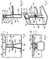
- the hanging seat 1b according to FIGS. 8 to 11 largely corresponds to the hanging seat 1 according to FIGS. 1 to 4.
- the hanging seat 1b differs from the hanging seat 1 essentially in that the hanging part 2b from above into the handle 3 fastened to the wall 4 or its crossbar 3 is hooked in.
- the carrier 9b, to which the seat part 5b and the backrest part 7b are fastened consists, like the carrier 9 according to FIGS. 1 to 4, of legs 11b, 12b which project downward over the seat part 5b and upwardly projecting tubular parts Have struts 13b and 14b.
- the backrest part 7b is fastened to the upper end of the struts 13b, 14b. For example, it can be attached to the strut ends or welded, glued or the like to them.
- the backrest part 7b is fastened to the struts 13b, 14b in such a way that its lower edge 41 is approximately at the level of the transverse web 3 the handle 3 is.
- the backrest part 7 of the embodiment according to FIGS. 1 to 4 lies at a distance below the crosspiece 3 of the handle 3.
- the hanging part 2b connects to the upper edge 42 of the backrest part 7b. It is designed like a bow and has an L-shaped cross section. With its shorter leg 43, the hanging part 2b adjoins the edge 42 of the backrest part 7b, while its longer leg 44 runs approximately parallel to the rear side 45 of the backrest part 7b.
- the seat and backrest parts 5b and 7b are otherwise of the same design as those of the seat 1.
- the carrier 9b largely corresponds to the carrier 9.
- the struts 13b and 14b have a smaller spacing from one another than the struts 13 and 14 of the carrier 9.
- the spacing of the struts 13b and 14b from one another corresponds to approximately one third of the width of the seat part 5b while it is in the embodiment according to FIGS. 1 to 4 is only slightly smaller than the seat width.
- the struts 13b, 14b pass approximately at the level of the seat part 5b into the legs 11b, 12b and are connected to one another at the level of the seat part 5b via the crosspiece 10b.
- the two tubular support parts 24b and 24b protrude rearward over the crosspiece 10b , with which the carrier 9 b is supported on the wall 4.
- the free ends 17b, 18b of the legs 11b, 12b are advantageously designed telescopically, as in the stand 9, in order to change the seat height.
- the legs 11b, 12b initially run in the area below the seat part 5b in alignment with the struts 13b, 14b.
- the carrier 9b is relatively narrow and light and yet has a secure stand on the ground.
- the seat 1 is first raised until its hanging part 2b with its lower edge 46 above the crosspiece 3 and lies above the handle opening 25. Thereafter, the seat 1b can be lowered until it rests with its supporting legs 11b, 12b on the floor, the hanging part 2b sliding with its leg 44 into the grip opening 25 of the grip 3 and the crosspiece 3 engages behind.
- the seat 1 then only has to be aligned with the floor and the wall 4 in such a way that the support 9b with its support parts 24b and 24b is securely supported on the wall 4.
- the seat 1b is then optimally aligned with the wall 4 and the floor, so that accidental tilting and slipping is avoided without any problems.
- the seat 1b has to be removed from the handle 3 for cleaning purposes or the like and removed from the wall 4, it only has to be raised upwards until the hanging part 2b is released from the hanging opening 25. Then the seat can be pulled forward over the handle 3 and removed from its assembled position. With the hanging part 2b, the seat 1b can be attached in a very simple manner only by slightly lifting it to the wall 4 and to the holder 3.
Landscapes
- Health & Medical Sciences (AREA)
- Public Health (AREA)
- Epidemiology (AREA)
- General Health & Medical Sciences (AREA)
- Passenger Equipment (AREA)
- Special Chairs (AREA)
- Supports Or Holders For Household Use (AREA)
Abstract
Description
- Fig. 1
- einen erfindungsgemäßen Einhängesitz in perspektivischer Darstellung,
- Fig. 2
- den Sitz nach Fig. 1 in Seitenansicht,
- Fig. 3
- die Einzelheit III in Fig. 2 in vergrößerter Darstellung,
- Fig. 4
- den Sitz nach Fig. 1 während der Montage,
- Fig. 5
- eine zweite Ausführungsform eines erfindungsgemäßen Einhängesitzes in einer Darstellung entsprechend Fig. 2,
- Fig. 6
- die Einzelheit VI in Fig. 5 in vergrößerter Darstellung und teilweise im Axialschnitt,
- Fig. 7
- die Belastungsverhältnisse beim erfindungsgemäßen Einhängesitz,
- Fig. 8
- eine weitere Ausführungsform eines erfindungsgemäßen Einhängesitzes in Stirnansicht,
- Fig. 9
- den Einhängesitz nach Fig. 8 in Draufsicht gemäß Pfeil IX in Fig. 8,
- Fig. 10
- den Einhängesitz nach Fig. 8 in Seitenansicht,
- Fig. 11
- den Einhängesitz gemäß Fig. 8 in perspektivischer Darstellung.

Claims (20)
- Einhängesitz zum Einhängen in einen Wandhalter, insbesondere einen Handlauf, einen Haltegriff oder dergleichen, mit einem Träger für eine Sitz- und/oder Rückenfläche und mit einem Einhängeteil zum Einhängen in den Handlauf oder dergleichen, dadurch gekennzeichnet, daß der Träger (9; 9a, 9b) mindestens eine Bodenstütze (11, 12; 11a, 11b, 12b) aufweist.
- Sitz nach Anspruch 1,
dadurch gekennzeichnet, daß die vorzugsweise durch zwei Standbeine gebildete Bodenstütze (11, 12; 11a; 11b, 12b) höhenverstellbar ausgebildet ist. - Sitz nach Anspruch 1 oder 2,
dadurch gekennzeichnet, daß die freien Enden (17, 18; 17a; 17b, 18b) der Standbeine (11, 12; 11a; 11b, 12b) teleskopartig ausgebildet sind. - Sitz nach einem der Ansprüche 1 bis 3,
dadurch gekennzeichnet, daß das Einhängeteil (2, 2) durch mindestens ein abgewinkeltes Ende, vorteilhaft durch teilkreisförmig abgebogene freie Enden von Streben (13, 14) des Trägers (9) gebildet ist.
- Sitz nach einem der Ansprüche 1 bis 3,
dadurch gekennzeichnet, daß das vorteilhaft mit einem Steckteil (33) durch eine sich in Längsrichtung des Trägers (9a) erstreckende Öffnung (30) gesteckte Einhängeteil (29) durch ein bügelartiges Teil gebildet ist, das am Träger (9a) vorzugsweise verstellbar befestigt ist. - Sitz nach Anspruch 5,
dadurch gekennzeichnet, daß das Einhängeteil (29) mit einem auf ein Gewinde (34) des Steckteiles (33) geschraubtes Sicherungsteil (32), vorzugsweise eine Mutter, gegenüber dem Wandhalter (3) verspannt ist. - Sitz nach Anspruch 5 oder 6,
dadurch gekennzeichnet, daß das Einhängeteil (29) ein zum Steckteil (33) im wesentlichen senkrecht verlaufendes Halteteil (37) aufweist, das eine Vertiefung (38) aufweist, in die ein Quersteg (3 - Sitz nach einem der Ansprüche 1 bis 7,
dadurch gekennzeichnet, daß das vorteilhaft L-förmigen Querschnitt aufweisende Einhängeteil (2b) am Lehnenteil (7b) vorgesehen ist, das vorzugsweise am oberen Ende der Streben (13b, 14b) angeordnet, vorzugsweise auf diesen steckend befestigt ist. - Sitz nach Anspruch 8,
dadurch gekennzeichnet, daß das Einhängeteil (2b) mit seinem kürzeren L-Schenkel (43) an das Lehnenteil (7b), vorzugsweise dessen Rückseite (45), anschließt, und daß vorzugsweise der längere L-Schenkel (44) des Einhängeteiles (2b) etwa parallel zum Lehnenteil (7b), vorzugsweise dessen Rückseite (45), verläuft. - Sitz nach Anspruch 8 oder 9,
dadurch gekennzeichnet, daß das Einhängeteil (2b) einteilig, vorzugsweise einstückig, mit dem Lehnenteil (7b) ausgebildet ist. - Sitz nach einem der Ansprüche 8 bis 10,
dadurch gekennzeichnet, daß das vorteilhaft symmetrisch zur Längsmittelebene des Lehnenteiles (7b) ausgebildete Einhängeteil (2b) kleinere Breite hat als das Lehnenteil (7b), vorzugsweise nur etwa halb so breit wie das Lehnenteil (7b) ist. - Sitz nach einem der Ansprüche 8 bis 11,
dadurch gekennzeichnet, daß der längere L-Schenkel (44) des Einhängeteiles (2b) etwa gleich hoch ist wie das Lehnenteil (7b), dessen unterer Rand (41) vorteilhaft etwa in Höhe eines Quersteges (3 - Sitz nach einem der Ansprüche 8 bis 12,
dadurch gekennzeichnet, daß das Einhängeteil (2b) bei montiertem Sitz (1b) mit dem freien Rand (46) des längeren L-Schenkels (44) in eine Öffnung (25) des Wandhalters (3) von oben ragt. - Sitz nach einem der Ansprüche 1 bis 13,
dadurch gekennzeichnet, daß der Abstand der Standbeine (11, 12; 11b, 12b) und/oder der Streben (13, 14; 13b, 14b) des Trägers (9; 9b) voneinander kleiner ist als die Breite des Sitzteiles (5; 5b) und/oder des Lehnenteiles (7; 7b). - Sitz nach einem der Ansprüche 1 bis 14,
dadurch gekennzeichnet, daß die Standbeine (11b, 12b) in einem mittleren Bereich nach unten divergierend verlaufen und vorzugsweise in ihrer unteren Hälfte größeren, vorzugsweise etwa doppelt so großen Abstand voneinander haben als in ihrem oberen, an den Sitzteil (5b) anschließenden Bereich. - Sitz nach einem der Ansprüche 1 bis 15,
dadurch gekennzeichnet, daß die Bodenstütze (11, 12; 11a; 11b, 12b) und die das Einhängeteil (2, 2 - Sitz nach einem der Ansprüche 1 bis 16,
dadurch gekennzeichnet, daß die vorteilhaft unter einem stumpfen Winkel an die Standbeine (11, 12; 11a; 11b, 12b) anschließenden Streben (13, 14; 13a; 13b, 14b) und die Standbeine (11, 12; 11a; 11b, 12b) durch Rohrabschnitte gebildet sind. - Sitz nach einem der Ansprüche 1 bis 17,
dadurch gekennzeichnet, daß die Sitzfläche (5; 5a) mit einem Rahmenteil (6) klappbar am vorteilhaft H- Form aufweisenden Träger (9; 9a; 9b), vorzugsweise einem Querstück (10; 10b) des Trägers, befestigt ist. - Sitz nach Anspruch 18,
dadurch gekennzeichnet, daß das Querstück (10; 10b) des Trägers (9; 9a; 9b) etwa in Höhe einer Übergangsstelle (15) der Standbeine (11, 12; 11a; 11b, 12b) in die das Lehnenteil (7; 7b) tragenden Streben (13, 14; 13a; 13b, 14b) liegt. - Sitz nach einem der Ansprüche 1 bis 19,
dadurch gekennzeichnet, daß die Standbeine (11, 12; 11a; 11b, 12b) zur Abstützung des Sitzes (1; 1a; 1b) an einer Wand (4) längenverstellbare, vorzugsweise teleskopartig ausgebildete Abstandhalter (24; 24a; 24b, 24b
Applications Claiming Priority (4)
| Application Number | Priority Date | Filing Date | Title |
|---|---|---|---|
| DE29807383U | 1998-04-23 | ||
| DE29807383U DE29807383U1 (de) | 1998-04-23 | 1998-04-23 | Einhängesitz zum Einhängen in einen Wandhalter |
| DE29813283U DE29813283U1 (de) | 1998-04-23 | 1998-07-25 | Einhängesitz zum Einhängen in einen Wandhalter |
| DE29813283U | 1998-07-25 |
Publications (3)
| Publication Number | Publication Date |
|---|---|
| EP0951849A2 true EP0951849A2 (de) | 1999-10-27 |
| EP0951849A3 EP0951849A3 (de) | 2001-03-21 |
| EP0951849B1 EP0951849B1 (de) | 2004-06-23 |
Family
ID=26061448
Family Applications (1)
| Application Number | Title | Priority Date | Filing Date |
|---|---|---|---|
| EP99106977A Expired - Lifetime EP0951849B1 (de) | 1998-04-23 | 1999-04-09 | Einhängesitz zum Einhängen in einen Wandhalter |
Country Status (2)
| Country | Link |
|---|---|
| EP (1) | EP0951849B1 (de) |
| AT (1) | ATE269652T1 (de) |
Cited By (5)
| Publication number | Priority date | Publication date | Assignee | Title |
|---|---|---|---|---|
| EP2153766A3 (de) * | 2008-08-15 | 2012-05-02 | Masco Bath Corporation | Wannensystem |
| EP2462840A1 (de) * | 2010-12-07 | 2012-06-13 | Hewi Heinrich Wilke Gmbh | Einhängesitz |
| USD784035S1 (en) | 2015-02-20 | 2017-04-18 | Seachrome Corporation | Profile seat |
| USD814818S1 (en) | 2015-02-20 | 2018-04-10 | Seachrome Corporation | Profile seat |
| USD814817S1 (en) | 2015-02-20 | 2018-04-10 | Seachrome Corporation | Profile seat |
Family Cites Families (5)
| Publication number | Priority date | Publication date | Assignee | Title |
|---|---|---|---|---|
| DE3413245A1 (de) * | 1984-04-07 | 1985-10-17 | Gerhard Prof. Dipl.-Ing. 2401 Zarpen Köhler | Wand-arbeitssitz |
| FR2648039A1 (fr) * | 1989-06-08 | 1990-12-14 | Ciedil | Siege de soins hygieniques |
| DE9409686U1 (de) * | 1994-06-16 | 1994-09-01 | Hillerkus, Karl Wilhelm, 32312 Lübbecke | Drehbarer Stuhl zum Einsteigen in eine Badewanne im Sitzen |
| US5467486A (en) * | 1994-10-31 | 1995-11-21 | Torbett B. Guenther | Foldable shower/tub seat |
| JP2000126063A (ja) * | 1998-10-23 | 2000-05-09 | Seiko Iryoki Seisakusho:Kk | 入浴用椅子 |
-
1999
- 1999-04-09 AT AT99106977T patent/ATE269652T1/de not_active IP Right Cessation
- 1999-04-09 EP EP99106977A patent/EP0951849B1/de not_active Expired - Lifetime
Cited By (5)
| Publication number | Priority date | Publication date | Assignee | Title |
|---|---|---|---|---|
| EP2153766A3 (de) * | 2008-08-15 | 2012-05-02 | Masco Bath Corporation | Wannensystem |
| EP2462840A1 (de) * | 2010-12-07 | 2012-06-13 | Hewi Heinrich Wilke Gmbh | Einhängesitz |
| USD784035S1 (en) | 2015-02-20 | 2017-04-18 | Seachrome Corporation | Profile seat |
| USD814818S1 (en) | 2015-02-20 | 2018-04-10 | Seachrome Corporation | Profile seat |
| USD814817S1 (en) | 2015-02-20 | 2018-04-10 | Seachrome Corporation | Profile seat |
Also Published As
| Publication number | Publication date |
|---|---|
| EP0951849A3 (de) | 2001-03-21 |
| ATE269652T1 (de) | 2004-07-15 |
| EP0951849B1 (de) | 2004-06-23 |
Similar Documents
| Publication | Publication Date | Title |
|---|---|---|
| DE69413551T2 (de) | Klapptisch | |
| DE3327783A1 (de) | Rollstuhl | |
| EP0951849B1 (de) | Einhängesitz zum Einhängen in einen Wandhalter | |
| DE29801465U1 (de) | Bausatz zur Ausrüstung bzw. Nachrüstung einer Festzelt-Sitzbank | |
| DE102013223128B4 (de) | Kinderhochstuhl | |
| DE29813283U1 (de) | Einhängesitz zum Einhängen in einen Wandhalter | |
| DE29620320U1 (de) | Wohnmobil, Motorhome o.dgl. | |
| DE10136216A1 (de) | Toilettensitz für Behinderte | |
| EP4285787B1 (de) | Anordnung, insbesondere zur nutzung als hängetisch | |
| EP0806164B1 (de) | Montageeinrichtung und Verfahren zur Montage von Möbeln und Waschplatzelementen an einer Wand | |
| DE29720586U1 (de) | Bausatz zur Ausrüstung bzw. Nachrüstung einer Festzelt-Sitzbank | |
| DE202004002690U1 (de) | Einhängesitz | |
| EP0405228B1 (de) | Halterung für schnell montierbare Sitzbänke oder Sitzträger, insbesondere von Tribünen | |
| DE202013010212U1 (de) | Kinderhochstuhl | |
| DE202017002759U1 (de) | Mobiler Hochsitz | |
| DE8705939U1 (de) | Bade-Wickel-Kombination | |
| DE202024104856U1 (de) | Fahrzeugsitz | |
| DE102024124567A1 (de) | Fahrzeugsitz | |
| DE202024106316U1 (de) | Als Strandkorb nutzbares Möbel | |
| DE29803167U1 (de) | Sitzbank | |
| DE1177283B (de) | Krankentransportfahrzeug mit Fuehrungsschienen fuer die Krankentragen | |
| AT409076B (de) | Möbel | |
| DE9412483U1 (de) | Sitzanordnung mit wenigstens zwei Sitzteilen | |
| DE9003425U1 (de) | Balkonhängetisch | |
| DE29510255U1 (de) | Konvertibele Sitz-Einrichtung für Fahrzeuge oder in solchen |
Legal Events
| Date | Code | Title | Description |
|---|---|---|---|
| PUAI | Public reference made under article 153(3) epc to a published international application that has entered the european phase |
Free format text: ORIGINAL CODE: 0009012 |
|
| AK | Designated contracting states |
Kind code of ref document: A2 Designated state(s): AT DE GB IT NL |
|
| AX | Request for extension of the european patent |
Free format text: AL;LT;LV;MK;RO;SI |
|
| PUAL | Search report despatched |
Free format text: ORIGINAL CODE: 0009013 |
|
| AK | Designated contracting states |
Kind code of ref document: A3 Designated state(s): AT BE CH CY DE DK ES FI FR GB GR IE IT LI LU MC NL PT SE |
|
| AX | Request for extension of the european patent |
Free format text: AL;LT;LV;MK;RO;SI |
|
| 17P | Request for examination filed |
Effective date: 20010704 |
|
| AKX | Designation fees paid |
Free format text: AT DE GB IT NL |
|
| 17Q | First examination report despatched |
Effective date: 20030410 |
|
| GRAP | Despatch of communication of intention to grant a patent |
Free format text: ORIGINAL CODE: EPIDOSNIGR1 |
|
| GRAS | Grant fee paid |
Free format text: ORIGINAL CODE: EPIDOSNIGR3 |
|
| GRAA | (expected) grant |
Free format text: ORIGINAL CODE: 0009210 |
|
| AK | Designated contracting states |
Kind code of ref document: B1 Designated state(s): AT DE GB IT NL |
|
| REG | Reference to a national code |
Ref country code: GB Ref legal event code: FG4D Free format text: NOT ENGLISH |
|
| REF | Corresponds to: |
Ref document number: 59909781 Country of ref document: DE Date of ref document: 20040729 Kind code of ref document: P |
|
| GBT | Gb: translation of ep patent filed (gb section 77(6)(a)/1977) |
Effective date: 20040726 |
|
| PLBE | No opposition filed within time limit |
Free format text: ORIGINAL CODE: 0009261 |
|
| STAA | Information on the status of an ep patent application or granted ep patent |
Free format text: STATUS: NO OPPOSITION FILED WITHIN TIME LIMIT |
|
| 26N | No opposition filed |
Effective date: 20050324 |
|
| PGFP | Annual fee paid to national office [announced via postgrant information from national office to epo] |
Ref country code: GB Payment date: 20100325 Year of fee payment: 12 |
|
| PGFP | Annual fee paid to national office [announced via postgrant information from national office to epo] |
Ref country code: NL Payment date: 20100512 Year of fee payment: 12 Ref country code: AT Payment date: 20100430 Year of fee payment: 12 |
|
| PG25 | Lapsed in a contracting state [announced via postgrant information from national office to epo] |
Ref country code: IT Free format text: LAPSE BECAUSE OF NON-PAYMENT OF DUE FEES Effective date: 20100409 |
|
| PGRI | Patent reinstated in contracting state [announced from national office to epo] |
Ref country code: IT Effective date: 20110616 |
|
| REG | Reference to a national code |
Ref country code: NL Ref legal event code: V1 Effective date: 20111101 |
|
| GBPC | Gb: european patent ceased through non-payment of renewal fee |
Effective date: 20110409 |
|
| REG | Reference to a national code |
Ref country code: AT Ref legal event code: MM01 Ref document number: 269652 Country of ref document: AT Kind code of ref document: T Effective date: 20110409 |
|
| PG25 | Lapsed in a contracting state [announced via postgrant information from national office to epo] |
Ref country code: NL Free format text: LAPSE BECAUSE OF NON-PAYMENT OF DUE FEES Effective date: 20111101 |
|
| PG25 | Lapsed in a contracting state [announced via postgrant information from national office to epo] |
Ref country code: AT Free format text: LAPSE BECAUSE OF NON-PAYMENT OF DUE FEES Effective date: 20110409 Ref country code: GB Free format text: LAPSE BECAUSE OF NON-PAYMENT OF DUE FEES Effective date: 20110409 |
|
| PGFP | Annual fee paid to national office [announced via postgrant information from national office to epo] |
Ref country code: IT Payment date: 20120329 Year of fee payment: 14 |
|
| PGFP | Annual fee paid to national office [announced via postgrant information from national office to epo] |
Ref country code: DE Payment date: 20130625 Year of fee payment: 15 |
|
| REG | Reference to a national code |
Ref country code: DE Ref legal event code: R119 Ref document number: 59909781 Country of ref document: DE |
|
| REG | Reference to a national code |
Ref country code: DE Ref legal event code: R119 Ref document number: 59909781 Country of ref document: DE Effective date: 20141101 |
|
| PG25 | Lapsed in a contracting state [announced via postgrant information from national office to epo] |
Ref country code: DE Free format text: LAPSE BECAUSE OF NON-PAYMENT OF DUE FEES Effective date: 20141101 |
|
| PG25 | Lapsed in a contracting state [announced via postgrant information from national office to epo] |
Ref country code: IT Free format text: LAPSE BECAUSE OF NON-PAYMENT OF DUE FEES Effective date: 20140409 |