EP0951926B1 - Fixation de ski de randonnée, de ski de Telemark ou de ski de fond - Google Patents
Fixation de ski de randonnée, de ski de Telemark ou de ski de fond Download PDFInfo
- Publication number
- EP0951926B1 EP0951926B1 EP99102015A EP99102015A EP0951926B1 EP 0951926 B1 EP0951926 B1 EP 0951926B1 EP 99102015 A EP99102015 A EP 99102015A EP 99102015 A EP99102015 A EP 99102015A EP 0951926 B1 EP0951926 B1 EP 0951926B1
- Authority
- EP
- European Patent Office
- Prior art keywords
- binding
- shoe
- ski
- clamping
- lever
- Prior art date
- Legal status (The legal status is an assumption and is not a legal conclusion. Google has not performed a legal analysis and makes no representation as to the accuracy of the status listed.)
- Expired - Lifetime
Links
- 230000027455 binding Effects 0.000 title claims description 80
- 238000009739 binding Methods 0.000 title claims description 80
- 230000007246 mechanism Effects 0.000 claims description 28
- 210000001872 metatarsal bone Anatomy 0.000 claims description 10
- XEEYBQQBJWHFJM-UHFFFAOYSA-N Iron Chemical compound [Fe] XEEYBQQBJWHFJM-UHFFFAOYSA-N 0.000 description 26
- 229910052742 iron Inorganic materials 0.000 description 13
- 238000010276 construction Methods 0.000 description 9
- 230000006835 compression Effects 0.000 description 6
- 238000007906 compression Methods 0.000 description 6
- 230000005540 biological transmission Effects 0.000 description 3
- 238000006073 displacement reaction Methods 0.000 description 3
- 238000005452 bending Methods 0.000 description 2
- 230000000881 depressing effect Effects 0.000 description 2
- 230000036316 preload Effects 0.000 description 2
- 229910001220 stainless steel Inorganic materials 0.000 description 2
- 239000010935 stainless steel Substances 0.000 description 2
- 230000007704 transition Effects 0.000 description 2
- 229910000831 Steel Inorganic materials 0.000 description 1
- 230000009471 action Effects 0.000 description 1
- 238000004873 anchoring Methods 0.000 description 1
- 230000008901 benefit Effects 0.000 description 1
- 239000011093 chipboard Substances 0.000 description 1
- 230000000295 complement effect Effects 0.000 description 1
- 230000008878 coupling Effects 0.000 description 1
- 238000010168 coupling process Methods 0.000 description 1
- 238000005859 coupling reaction Methods 0.000 description 1
- 230000007423 decrease Effects 0.000 description 1
- 230000003247 decreasing effect Effects 0.000 description 1
- 230000001419 dependent effect Effects 0.000 description 1
- 230000000994 depressogenic effect Effects 0.000 description 1
- 230000000694 effects Effects 0.000 description 1
- 238000005516 engineering process Methods 0.000 description 1
- 230000002349 favourable effect Effects 0.000 description 1
- 230000006872 improvement Effects 0.000 description 1
- 230000003993 interaction Effects 0.000 description 1
- 239000000463 material Substances 0.000 description 1
- 230000004048 modification Effects 0.000 description 1
- 238000012986 modification Methods 0.000 description 1
- 239000010959 steel Substances 0.000 description 1
Images


Classifications
-
- A—HUMAN NECESSITIES
- A63—SPORTS; GAMES; AMUSEMENTS
- A63C—SKATES; SKIS; ROLLER SKATES; DESIGN OR LAYOUT OF COURTS, RINKS OR THE LIKE
- A63C9/00—Ski bindings
-
- A—HUMAN NECESSITIES
- A63—SPORTS; GAMES; AMUSEMENTS
- A63C—SKATES; SKIS; ROLLER SKATES; DESIGN OR LAYOUT OF COURTS, RINKS OR THE LIKE
- A63C9/00—Ski bindings
- A63C9/20—Non-self-releasing bindings with special sole edge holders instead of toe-straps
-
- A—HUMAN NECESSITIES
- A63—SPORTS; GAMES; AMUSEMENTS
- A63C—SKATES; SKIS; ROLLER SKATES; DESIGN OR LAYOUT OF COURTS, RINKS OR THE LIKE
- A63C2201/00—Use of skates, skis, roller-skates, snowboards and courts
- A63C2201/06—Telemark
Definitions
- the invention relates to a touring, telemark or cross-country ski binding with a support device for supporting the front portion of an associated shoe, in particular a front sole section of the same on a ski or the same sports equipment to the front, up and to the side as well with a holding device to hold the shoe in the support device to keep such that the heel of the shoe can be raised freely is.
- Such ski bindings for touring, telemark or cross-country skiing are generally known. It becomes exemplary in this regard referred to the applicant's WO 96/23558.
- the sole is supported in the Area of the front sole end, so that with increasing Lifting the heel of the shoe in a correspondingly increasing manner Contact between shoe and ski or similar sports equipment get lost. Leadership stability and efficiency suffer from this the power transmission.
- Another ski binding is known from the document according to Article 54 (3) EPC WO 99/47219 a stop device and an elastic device Has receiving device.
- the device forming the stop serves to accommodate the front end of the shoe while the elastic cradle with the sole of a ski boot is engaged.
- the elastic cradle is on the binding behind the the stop anchoring device.
- the present invention is based on the object To make the binding even more ergonomic, especially the Operation of the binding ergonomically favorable for the user should be done.
- step-in construction according to the independent claim 1 and the dependent claims 2 to 5 is in the release position the binding the clamping means of the holding device thanks to an elastically preloaded toggle mechanism in an upward swiveled position, when entering in the binding and kicking of the shoe the toggle mechanism reaches a lower over-center position, in who moved the clamping device into the shoe closed position and is held.
- the Toggle mechanism through a rear, parallel to the Ski longitudinal direction extending, hinged to the ski or the binding Lever and a front, parallel to the longitudinal direction of the ski extending, on the longitudinally displaceable clamping means on the one hand and at the front end of the rear lever on the other hand articulated lever formed, the clamping means the holding device on the front lever of the toggle mechanism supports, preferably at the top of the front lever. They are in the release position of the binding both levers of the toggle mechanism upward in a V-shape angled so that the articulation between the two Lever is above the dead center line. In the lower one The articulation is located above the dead center position between the two levers below the dead center line.
- the toggle mechanism is preloaded elastically by a helical compression spring, which is attached to the common Articulated connection between the front and rear lever on the one hand and on a fixed part in front of it the binding or the binding housing on the other hand.
- a helical compression spring is attached to the common Articulated connection between the front and rear lever on the one hand and on a fixed part in front of it the binding or the binding housing on the other hand.
- the helical compression spring is in the lower dead center position compressed so that the desired elastic prestress is given, which is characterized by a simple, on the joint joint between Release the opening mechanism using the two levers leaves while moving the joint joint joint in the upper dead center position.
- the opening mechanism is characterized by an opening means, which with a lever or the like arranged in front of or behind the shoe Actuator is coupled, such that at Action on the actuator of the toggle mechanism can be moved out of a lower dead center position.
- the Opening means can e.g. a longitudinally displaceable one Include wedge, one wedge surface against the front or rear lever connecting joint axis can be set by raising the same over the dead center line time.
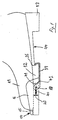
- the double arrow 43 in FIG. 1 also indicates that Possibility of height adjustment of the pivot axis 18, e.g. through two or more elongated holes 41 arranged one above the other.
- the clamping plate 39 is with a not shown Coupling mechanism coupled, e.g. with one in front of the toe iron 14 arranged clamping lever, preferably via a rigid Power transmission element, e.g. one below the toe iron longitudinally displaceable linkage, which with the Clamping plate 39 on the one hand and the mentioned clamping lever on the other hand is connected.
- a rigid Power transmission element e.g. one below the toe iron longitudinally displaceable linkage
- the clamping plate 39 is in its Shown closed position.
- the rear end of the clamping plate 39 is bent forward in a U-shape. It engages in one correspondingly or complementarily shaped recess or Undercut 26 at the rear end of the front sole 12, i.e. immediately in front of the shoe arch 44, as shown in FIGS Figures 1 and 2 is shown.
- the clamping plate 39 extends if the shoe is depressed below the tread of the Front sole 12. So that the clamping plate 39 does not align with the rear End of the toe iron 14 collides, the front half of the Clamping plate 39 excluded accordingly. So that at Lifting the heel 13 of the clamping plate 39 accordingly Figure 2 swivel upwards without collision.
- the pivot axis 18 of the clamping plate 39 is located at the shown binding about halfway up the Front sole 12. As briefly explained above, it can also do something be placed higher or lower, preferably by arrangement corresponding elongated holes 41.
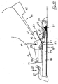
- the binding according to Figures 3 and 4 differs of that of Figures 1 and 2 essentially only in that the relatively rigid clamping plate 39 by a Tension cable 25 is replaced, which on the outside of the arranged two side jaws 16 of the toe iron 14 Deflection elements 65 held longitudinally displaceable (double arrow 45) and can be deflected upwards when the shoe heel 13 is lifted, as shown in Figure 4. Specifically are the Outside of the two side jaws 16 of the toe iron 14 two Deflection elements 65 arranged, in different Height and different longitudinal position, so that the longitudinal and / or The height of the cable deflection can be individually adjusted is.
- the tension cable 25 is with one for cable ties usual operating mechanism in front of the toe iron 14 connected. On one side, the tension cable 25 can still Tension spring element include to in under elastic bias To be kept in the closed position. On the sole side, this applies Tension cable into one at the rear end of the front sole 12 trained undercut 26 a.
- FIGS. 5 to 7 show a new step-in binding shown in combination with a holding device similar that of Figures 1 and 2.
- the holding device is however in contrast to the binding according to FIG. 1 and 2 formed by a flexible elastic tension band 24, which is mounted for longitudinal displacement in a binding housing 46, with a support device at the top of the binding housing 14 is mounted in the form of a toe iron.
- the Strap 24 is specific between the base plate of the toe iron 14 and the top of the binding housing 46 is longitudinally displaceable stored.
- the rear end of the strap 24 is similar to the rear end of the clamping plate 39 according to the Figures 1 and 2 bent forward U-shaped. The interaction between front sole 12 and strap 24 takes place in the described with reference to Figures 1 and 2.
- the toggle mechanism 47 includes a rear, itself extending parallel to the longitudinal direction of the ski and on the binding housing 46 hinged lever 50 and a front, yourself also extending parallel to the longitudinal direction of the ski, on longitudinally mounted tension band 24 on the one hand and on articulated front end of the rear lever 50 on the other hand Lever 51, the strap 24 on the top of the supports front lever 51 of the toggle mechanism. Concrete the rear end of the strap 24 is supported on one protruding projection at the rear end of the front lever 51 from.
- Swivel axis 53 That associated with the front end of the front lever 51 Swivel axis 53 is within an elongated hole passage 52 in Binding housing 46 mounted longitudinally. This Pivot axis 53 is also with a flat element 54 connected to the front end of the strap 24, here specifically a rivet connection 55 is provided.
- the toggle mechanism 47 is also an opening means 56 assigned, which with a here in front of the shoe 11 or Toe iron 14 arranged actuating lever 57 is coupled, such that when acting on the operating lever in the direction arrow 58 in FIG. 6 shows the toggle mechanism 47 its lower dead center position to the upper Excess dead center position according to Figure 5 is movable.
- the Opening means 56 comprises a longitudinally displaceable Wedge 59, one, namely front wedge surface 60 against the connecting the front and rear levers Hinge axis 61 is adjustable while raising the same over the Dead center line created by the connection between the front and rear linkage of front and rear lever is defined.
- the clamping means by means of a longitudinally displaceable clamping plate 39 formed corresponding to that according to Figures 1 and 2, the clamping plate 39 specifically on a longitudinally displaceable mounted bearing bracket 62 is pivotally mounted.
- This Bearing bracket is with the front pivot axis 53 of the front Lever 51 connected, again by a flat element 54th
- the opening wedge 59 is connected to the operating lever 57 by a rigid linkage 63 connected, which within the binding housing 46 is mounted for longitudinal displacement.
- the operating lever could also be behind the heel be arranged. In this case the opening mechanism would be equally trained, only effective in the backward direction.
- At the top of the operating lever 57 is another Recess 64 formed for a ski pole tip, so that with the ski pole by pressing in the direction of arrow 58 the binding can be opened easily without the skier bending down got to.
- the front sole 12 only at the front sole end through this overlapping Knaggen 15 held.
- the lugs 15 are on the inside Side jaws 16 of the toe iron 14 are formed.
- the binding according to FIG. 11 is characterized by that the lugs 15 of a toe iron so far back are offset that the front sole 12 on the ski 10 to metatarsal zone is held so that when lifting the Heel 13 a bend of the front sole 12 only from the metatarsal zone 17 is possible.
- the bonds according to FIGS. 12 and 13 are also formed.
- all holding devices have in common that they are in Area of the metatarsal zone 17 are connected, namely in order to be approximately parallel to the longitudinal direction of the shoe Sole tread or horizontally extending axis 18 biegoder held pivotable, in particular pivotable are stored. Furthermore, all holding devices common that they are at the rear end of the front sole, especially in the transition area to the shoe arch on this can be connected.
- the holding device comprises one in the metatarsal area 17 around a horizontal one Transverse axis 18 sole plate 34 pivotally mounted with a longitudinally movable (double arrow 36) movable sole clamping means 35, which in the region of the articulation of the soleplate 34, i.e. in the area of the horizontal transverse axis 18 deflectable and with one in the front area of the support device 14 about a horizontal transverse axis 30 in the direction of Double arrow 31 pivotally mounted clamping lever 29 connected is.
- the tensioning means is 35 a flat band made of stainless steel, which within the Sole plate 34 is longitudinally displaceable in the direction of the double arrow 36 is stored.
- the rear free end of the Tension band 35 is bent like a hook upwards and forwards in a complementary transverse groove on the underside of the front sole 12 can intervene, as shown in Figure 11 is.
- the strap 35 is relatively rigid, it ends within the sole plate 34 before the articulation thereof the axis 18.
- the front end of the strap 35 preferably with a flexible cable, in particular Steel wire connected in the region of the hinge axis 18 deflected and forward to the inside of the binding housing Clamping lever 29 is guided.
- the strap 35 can by a spring not shown here in the shoe release position be biased so that the movement of the strap 35 in the Shoe holding position according to Figure 14 against this elastic pre-tension takes place, and by appropriate Depressing the tensioning lever 29 downwards into a front Position according to Figure 11. In this position the clamping lever 29 is then preferably in an over-center position. If the tensioning lever 29 is outside this dead center position brought, causes the aforementioned elastic bias on the Strap 35 a movement of the same in the shoe release position.
- the elastic preload mentioned also affects Lifting the heel 13 off, albeit in a relatively small amount Dimensions. This creates a corresponding provision between the shoe and causes skiing or similar sports equipment.
- the binding according to FIG. 12 differs from that of Figure 11 in that the holding device flexible elastic strap 24 made of stainless steel or the like permanently flexible material and at the same time as sole tensioning means serves. 13 in the embodiment the holding device a tension cable 25.
- This tension cable 25 engages in one on the underside of the front sole 12, namely formed in the rear area of the same transverse groove. Concrete this groove is an undercut 26th
- the strap 24 has the advantage that this is the curvature the front sole 12 in the area between the metatarsal zone 17 and Arches also defined.
- the front sole 12 is supported in this area on the strap 24 literally.
- the Tension cable construction 25 can operate in a similar manner be when the tension cable is completely at the bottom of the Front sole 12 bears, that is, not laterally on the front sole 12 is guided past, as is the case in FIG. 13.
- the Corresponding clamping block is marked with the reference number 27.
- This clamping block is inside the binding housing, here within the front sole section assigned support plate 21 in the direction of the double arrow 22 stored back and forth, and for this purpose via a rigid connecting element 28 connected to the locking lever 29, its function in more detail with reference to FIG 11 is described.
- the clamping lever 29 the clamping block 27 and thus the associated clamping plate 24 Can be moved back and forth in the longitudinal direction of the shoe, i.e. the latter out a shoe release position into a shoe hold position corresponding to Figure 12 and vice versa.
- the back and forth Movement of the clamping plate 24 is also in Figure 12 with the Double arrow 36 displayed.
- the clamping plate 24 has a width on, which is less than the width of the support plate 21 and thus also less than the width of the front sole 12.
- the front end of the To link the tensioning strap 24 to the tensioning block 27, i.e. in the clamping block 27 is also possible to use the front end of the To link the tensioning strap 24 to the tensioning block 27, i.e. in the clamping block 27 to be pivotable about a horizontal transverse axis corresponding to the transverse axis 18 in Figure 11.
- the entire holding device, i.e. Tension strap 24, associated tension block 27 and Connecting element 28 reciprocates in the longitudinal direction of the shoe, to release the shoe 11 or on the support device 14 hold.
- the clamping means 24, 25 or the associated Connection elements 27, 32 in the direction of the shoe release position preload elastic.
- the fasteners 28 not be rigid; then it can flexible tensioning cables or wires can also be used.
- bindings 12 and 13 of the locking lever 29 in the shoe holding position in an over-dead center position are also conceivable.
- Both the tensioning cable 25 and the tensioning plate 24 effect when lifting the heel 13 a provision between Shoe and ski, which with increasing lifting of the heel 13 increases accordingly.
- the sole plate 34 slightly lower than the sole support surface 38 in the area of the front sole section to assign associated support device 14. This is one Bulging of the front sole 12 in the transition area between the Sole support surface 38 and the sole plate 34 down possible if the heel 13 is raised up. at This is the binding according to FIGS. 12 and 13 less problematic since neither the tension cable 25 nor the Strap 24 a bulge of the front sole down when Obstruct lifting of the heel 13. This is especially true for the binding according to Figure 13, in which the tension cable is guided past the front sole 12.
- pivot axis 18 are at the level of the front sole 12 is, the pivot axis 18 is arranged laterally Trunnions defined, their axes at the level of each other aligned.
- the pivot pins are then in the side Cheeks of the binding housing arranged between which the Shoe, in particular the front sole 12 of the same is placed.
- the support device a locking device for one on the bottom the sole in the metatarsal area of the same Undercut, transverse axis or the like sole holding element may include.
- the cross axis mentioned is preferably within one at the bottom of the sole trained recess arranged and with the sole integrated.
- the locking device comprises a locking hook, which engages behind the transverse axis and thus the front one Sole section firmly attached to the ski or between the ski and boot arranged binding plate holds.
- the mentioned hook is connected to a locking lever on the support device 14 is pivotally mounted, preferably around one Horizontal axis extending transversely to the longitudinal direction of the ski. at this binding can be used on cross-sole support elements 15, as indicated in FIGS. 11 to 13, to be dispensed with.
- the support elements 15 to support the front sole section up into the Figures 11 to 13 also only indicated schematically.
- the Representation should also be a support device of the aforementioned Kind of include.
- the toggle mechanism 47 by a Helical compression spring is elastically biased. This supports themselves in the illustrated embodiments with their rear End at the articulation between the front and rear Lever on the one hand and with its front end on the binding housing 46 on the other hand.
- the helical compression spring 65 mentioned axially compressed compared to the top dead center position according to Figures 5 and 8.
- the elastic bias the helical compression spring 65 ensures bistable Location of the lever 50, 51 or the toggle mechanism 47 in the lower and upper dead center position.
- the dead center line is defined by the connecting line between the rear linkage of the rear lever 50 and the front Linkage of the front lever 51.
- the helical compression spring 65 described a helical tension spring between the rear linkage of the rear lever 50 on the one hand and the front linkage of the front lever 51 on the other hand. This also makes the required Bi-stability of the toggle mechanism 47 reached.
Landscapes
- Footwear And Its Accessory, Manufacturing Method And Apparatuses (AREA)
Claims (5)
- Fixation de ski de randonnée, de ski de Telemark ou de ski de fond comportant un dispositif de soutien (14) pour soutenir sur un ski (10), vers l'avant, vers le haut et vers le côté, la partie avant d'une chaussure associée, ainsi qu'un dispositif de retenue (24) pour maintenir la chaussure (11) dans le dispositif de soutien (14), de façon que le talon (13) de la chaussure puisse être soulevé librement, le dispositif de retenue comprenant un moyen de serrage, sous la forme d'un câble de serrage, d'une bande de serrage (24) ou d'une plaque de serrage (39), raccordé, dans la région de la zone métatarsienne (17), au ski ou à la fixation ou à son boítier (46), et agissant sur la semelle avant (12) de la chaussure (11) derrière la zone métatarsienne (17),
caractérisée en ce que
dans la position de déverrouillage de la fixation, le moyen de serrage du dispositif de retenue (24, 39) est maintenu, par un mécanisme à leviers coudés (47) précontraint élastiquement, dans une position pivotée vers le haut ou recourbée vers le haut, et lorsque l'on enfile la fixation, le mécanisme à leviers coudés (47) parvient, en pressant vers le bas la chaussure (11), dans une position de point mort dépassé dans laquelle le moyen de serrage est déplacé et maintenu en position fermée. - Fixation selon la revendication 1,
caractérisée en ce que
le mécanisme à leviers (47) est formé par un levier (50) arrière, s'étendant parallèlement à la direction longitudinale du ski, articulé au ski ou à la fixation ou à son boítier (46), et par un levier (51) avant, s'étendant également parallèlement à la direction longitudinale du ski, articulé d'une part au moyen de serrage monté de manière à coulisser longitudinalement, du dispositif de retenue (24, 39), et d'autre part à l'extrémité avant du levier arrière (50), le moyen de serrage (24) prenant appui contre le levier avant (51) du mécanisme à leviers coudés. - Fixation selon la revendication 1 ou 2,
caractérisée en ce que
au mécanisme à leviers coudés (47) est associé un moyen d'ouverture (56) qui est couplé à un élément d'actionnement (levier 57) disposé devant ou derrière la chaussure de manière que lorsque l'on agit sur l'élément d'actionnement, le mécanisme à leviers coudés (47) est déplacable à l'extérieur de sa position basse de point mort dépassé. - Fixation selon la revendication 3,
caractérisée en ce que
le moyen d'ouverture (56) comprend un coin (59) monté de manière à coulisser longitudinalement dont une surface de coin (60) contre laquelle peut être placé l'axe d'articulation (61) reliant entre eux le levier avant et le levier arrière, en soulevant celui-ci de la position basse de point mort dépassé, dans la position haute de point mort dépassé, en passant par la ligne de point mort dépassé. - Fixation selon l'une des revendications 1 à 4,
caractérisée en ce que
le moyen de serrage est une bande de serrage (24) présentant l'élasticité d'un ressort ou une plaque de serrage (39) articulée à un étrier d'appui (62) monté de manière à coulisser longitudinalement.
Applications Claiming Priority (2)
| Application Number | Priority Date | Filing Date | Title |
|---|---|---|---|
| DE19818517 | 1998-04-24 | ||
| DE19818517A DE19818517C2 (de) | 1997-09-12 | 1998-04-24 | Touren-, Telemark- oder Langlauf-Skibindung |
Publications (2)
| Publication Number | Publication Date |
|---|---|
| EP0951926A1 EP0951926A1 (fr) | 1999-10-27 |
| EP0951926B1 true EP0951926B1 (fr) | 2004-12-01 |
Family
ID=7865767
Family Applications (1)
| Application Number | Title | Priority Date | Filing Date |
|---|---|---|---|
| EP99102015A Expired - Lifetime EP0951926B1 (fr) | 1998-04-24 | 1999-02-01 | Fixation de ski de randonnée, de ski de Telemark ou de ski de fond |
Country Status (1)
| Country | Link |
|---|---|
| EP (1) | EP0951926B1 (fr) |
Families Citing this family (6)
| Publication number | Priority date | Publication date | Assignee | Title |
|---|---|---|---|---|
| WO2001066204A1 (fr) * | 2000-03-07 | 2001-09-13 | Rottefella As | Fixation de ski |
| EP1509288B1 (fr) * | 2002-06-04 | 2006-06-21 | Rottefella AS | Fixation de ski, notamment fixation de ski de randonnee, de telemark ou de fond |
| SI21412A (sl) * | 2003-01-31 | 2004-08-31 | Alpina, Tovarna Obutve, D.D., Žiri | Zapiralni mehanizem za tek na smučeh |
| DE102004024881A1 (de) | 2004-05-19 | 2005-07-14 | Rottefella As | Langlauf- oder Telemarkbindung |
| US9776065B2 (en) | 2005-01-10 | 2017-10-03 | Rottefella As | Ski, or similar device for sliding on snow, having a mounting aid for a binding |
| EP2111900B1 (fr) | 2008-04-25 | 2011-12-14 | Rottefella AS | Cartouche de ressort pour fixation de ski |
Citations (2)
| Publication number | Priority date | Publication date | Assignee | Title |
|---|---|---|---|---|
| WO1996023558A1 (fr) * | 1995-02-02 | 1996-08-08 | Rottefella A/S | Combinaison d'une fixation de ski et d'une chaussure adaptee a ladite fixation |
| WO1999047219A1 (fr) * | 1998-03-19 | 1999-09-23 | Salomon S.A. | Dispositif de liaison d'une chaussure a un article de sport |
Family Cites Families (3)
| Publication number | Priority date | Publication date | Assignee | Title |
|---|---|---|---|---|
| FR2595951B1 (fr) * | 1986-03-19 | 1989-08-11 | Salomon Sa | Ensemble constitue par une chaussure de ski de fond ou de randonnee et un dispositif de retenue de l'avant de cette chaussure sur un ski |
| DE19503397A1 (de) | 1995-02-02 | 1996-08-08 | Rottefella As | Kombination einer Skibindung und eines daran angepaßten Schuhs |
| DE19517791A1 (de) | 1995-05-15 | 1996-11-21 | Rottefella As | Kombination einer Skibindung und eines daran angepaßten Schuhs |
-
1999
- 1999-02-01 EP EP99102015A patent/EP0951926B1/fr not_active Expired - Lifetime
Patent Citations (2)
| Publication number | Priority date | Publication date | Assignee | Title |
|---|---|---|---|---|
| WO1996023558A1 (fr) * | 1995-02-02 | 1996-08-08 | Rottefella A/S | Combinaison d'une fixation de ski et d'une chaussure adaptee a ladite fixation |
| WO1999047219A1 (fr) * | 1998-03-19 | 1999-09-23 | Salomon S.A. | Dispositif de liaison d'une chaussure a un article de sport |
Also Published As
| Publication number | Publication date |
|---|---|
| EP0951926A1 (fr) | 1999-10-27 |
Similar Documents
| Publication | Publication Date | Title |
|---|---|---|
| EP1292369B1 (fr) | Ensemble constitue d'une fixation de ski et d'une chaussure de ski | |
| EP0806977B1 (fr) | Combinaison d'une fixation de ski et d"une chaussure adaptee a ladite fixation | |
| DE19653162C1 (de) | Snowboardbindung | |
| EP0265459A1 (fr) | Fixation de ski de fond. | |
| WO1997047367A1 (fr) | Fixation pour ski de fond ou ski de randonnee | |
| EP0934762A1 (fr) | Fixation pour planche de glisse, notamment snowboard | |
| DE69504518T2 (de) | Bindung für einen schuh auf einem snowboard | |
| EP1385585A1 (fr) | Fixation de ski | |
| EP1100601A1 (fr) | Fixation, en particulier pour ski de randonnee | |
| DE69925214T2 (de) | Vorrichtung zum verbinden eines schuhs mit einem sportartikel | |
| EP0951926B1 (fr) | Fixation de ski de randonnée, de ski de Telemark ou de ski de fond | |
| DE2707626A1 (de) | Langlaufbindung | |
| EP0829281B1 (fr) | Dispositif de retenue d'une chaussure pour une fixation de ski détachable | |
| EP1586354A1 (fr) | Fixation de ski de Telemark ou de ski de fond ,ainsi que ses chaussures adaptés | |
| EP0830185B1 (fr) | Dispositif pour fixation de ski de fond, en particulier pour la pratique du patinage | |
| DE10319675A1 (de) | Skibindung, insbesondere Touren-, Telemark- oder Langlaufbindung | |
| DE4424737C1 (de) | Snowboardbindung | |
| EP0908204A2 (fr) | Fixation de ski de randonnée, de ski de Telemark ou de ski de fond | |
| EP1144056A1 (fr) | Fixation de ski de telemark | |
| DE19818517C2 (de) | Touren-, Telemark- oder Langlauf-Skibindung | |
| EP1790396B1 (fr) | Fixation de ski, en particulier fixation de telemark | |
| EP1174165B1 (fr) | Construction de fixation | |
| DE3606645A1 (de) | Langlauf- oder tourenskibindung | |
| EP1468710B1 (fr) | Fixation de ski, en particulier pour ski de randonnee, telemark ou ski de fond | |
| DE10329629B4 (de) | Skibindung |
Legal Events
| Date | Code | Title | Description |
|---|---|---|---|
| PUAI | Public reference made under article 153(3) epc to a published international application that has entered the european phase |
Free format text: ORIGINAL CODE: 0009012 |
|
| AK | Designated contracting states |
Kind code of ref document: A1 Designated state(s): DE FR |
|
| AX | Request for extension of the european patent |
Free format text: AL;LT;LV;MK;RO;SI |
|
| 17P | Request for examination filed |
Effective date: 19991221 |
|
| AKX | Designation fees paid |
Free format text: DE FR |
|
| 17Q | First examination report despatched |
Effective date: 20030114 |
|
| GRAP | Despatch of communication of intention to grant a patent |
Free format text: ORIGINAL CODE: EPIDOSNIGR1 |
|
| GRAS | Grant fee paid |
Free format text: ORIGINAL CODE: EPIDOSNIGR3 |
|
| GRAA | (expected) grant |
Free format text: ORIGINAL CODE: 0009210 |
|
| AK | Designated contracting states |
Kind code of ref document: B1 Designated state(s): DE FR |
|
| REF | Corresponds to: |
Ref document number: 59911160 Country of ref document: DE Date of ref document: 20050105 Kind code of ref document: P |
|
| PLBE | No opposition filed within time limit |
Free format text: ORIGINAL CODE: 0009261 |
|
| STAA | Information on the status of an ep patent application or granted ep patent |
Free format text: STATUS: NO OPPOSITION FILED WITHIN TIME LIMIT |
|
| 26N | No opposition filed |
Effective date: 20050902 |
|
| ET | Fr: translation filed | ||
| REG | Reference to a national code |
Ref country code: FR Ref legal event code: PLFP Year of fee payment: 18 |
|
| REG | Reference to a national code |
Ref country code: FR Ref legal event code: PLFP Year of fee payment: 19 |
|
| PGFP | Annual fee paid to national office [announced via postgrant information from national office to epo] |
Ref country code: FR Payment date: 20170112 Year of fee payment: 19 Ref country code: DE Payment date: 20170125 Year of fee payment: 19 |
|
| REG | Reference to a national code |
Ref country code: DE Ref legal event code: R119 Ref document number: 59911160 Country of ref document: DE |
|
| REG | Reference to a national code |
Ref country code: FR Ref legal event code: ST Effective date: 20181031 |
|
| PG25 | Lapsed in a contracting state [announced via postgrant information from national office to epo] |
Ref country code: DE Free format text: LAPSE BECAUSE OF NON-PAYMENT OF DUE FEES Effective date: 20180901 |
|
| PG25 | Lapsed in a contracting state [announced via postgrant information from national office to epo] |
Ref country code: FR Free format text: LAPSE BECAUSE OF NON-PAYMENT OF DUE FEES Effective date: 20180228 |