EP0952016A2 - Automotive ventilation housing with self supporting film valve having a convex, semi-cylindrical shape - Google Patents
Automotive ventilation housing with self supporting film valve having a convex, semi-cylindrical shape Download PDFInfo
- Publication number
- EP0952016A2 EP0952016A2 EP99200808A EP99200808A EP0952016A2 EP 0952016 A2 EP0952016 A2 EP 0952016A2 EP 99200808 A EP99200808 A EP 99200808A EP 99200808 A EP99200808 A EP 99200808A EP 0952016 A2 EP0952016 A2 EP 0952016A2
- Authority
- EP
- European Patent Office
- Prior art keywords
- opening
- film sheet
- rollers
- edges
- interior perimeter
- Prior art date
- Legal status (The legal status is an assumption and is not a legal conclusion. Google has not performed a legal analysis and makes no representation as to the accuracy of the status listed.)
- Withdrawn
Links
Images

Classifications
-
- B—PERFORMING OPERATIONS; TRANSPORTING
- B60—VEHICLES IN GENERAL
- B60H—ARRANGEMENTS OF HEATING, COOLING, VENTILATING OR OTHER AIR-TREATING DEVICES SPECIALLY ADAPTED FOR PASSENGER OR GOODS SPACES OF VEHICLES
- B60H1/00—Heating, cooling or ventilating devices
- B60H1/00642—Control systems or circuits; Control members or indication devices for heating, cooling or ventilating devices
- B60H1/00664—Construction or arrangement of damper doors
-
- B—PERFORMING OPERATIONS; TRANSPORTING
- B60—VEHICLES IN GENERAL
- B60H—ARRANGEMENTS OF HEATING, COOLING, VENTILATING OR OTHER AIR-TREATING DEVICES SPECIALLY ADAPTED FOR PASSENGER OR GOODS SPACES OF VEHICLES
- B60H1/00—Heating, cooling or ventilating devices
- B60H1/00642—Control systems or circuits; Control members or indication devices for heating, cooling or ventilating devices
- B60H1/00664—Construction or arrangement of damper doors
- B60H1/00692—Damper doors moved by translation, e.g. curtain doors
-
- B—PERFORMING OPERATIONS; TRANSPORTING
- B60—VEHICLES IN GENERAL
- B60H—ARRANGEMENTS OF HEATING, COOLING, VENTILATING OR OTHER AIR-TREATING DEVICES SPECIALLY ADAPTED FOR PASSENGER OR GOODS SPACES OF VEHICLES
- B60H1/00—Heating, cooling or ventilating devices
- B60H1/00642—Control systems or circuits; Control members or indication devices for heating, cooling or ventilating devices
- B60H1/00664—Construction or arrangement of damper doors
- B60H2001/00728—Film doors
-
- Y—GENERAL TAGGING OF NEW TECHNOLOGICAL DEVELOPMENTS; GENERAL TAGGING OF CROSS-SECTIONAL TECHNOLOGIES SPANNING OVER SEVERAL SECTIONS OF THE IPC; TECHNICAL SUBJECTS COVERED BY FORMER USPC CROSS-REFERENCE ART COLLECTIONS [XRACs] AND DIGESTS
- Y10—TECHNICAL SUBJECTS COVERED BY FORMER USPC
- Y10T—TECHNICAL SUBJECTS COVERED BY FORMER US CLASSIFICATION
- Y10T137/00—Fluid handling
- Y10T137/6851—With casing, support, protector or static constructional installations
- Y10T137/6855—Vehicle
- Y10T137/6881—Automotive
Definitions
- This invention relates to automotive ventilation system valves in general, and specifically to a rotary film valve which maintains a convex, semi cylindrical shape in a self supporting manner, and which can moved along the interior surface of the perimeter of the housing opening without substantial relative rubbing.
- HVAC systems heating, ventilation and air conditioning systems
- the housing includes the two heat exchangers, the cold evaporator core and hot heater core, as well as the various valves and doors that route intake air through or around the two to create outlet air of a desired temperature.
- Outlet openings in the housing and instrument panel direct the air up at the windshield, forwardly at the occupant, or downwardly at an occupants' feet. These openings are covered or uncovered by a suitable valve, as selected by the vehicle occupant.
- the outlet openings in descending order of height, are called defrost, air conditioning, and heat, although air of any temperature may be directed through any of them.
- Another known outlet valve is a rotary valve.
- the various outlet openings have perimeter edges disposed in semi cylindrical arcs and a semi cylindrical solid door swings up and down inside the housing to cover and uncover the openings. Seal rubbing is also a problem with a rotary valve.
- Another drawback with a solid rotary valve is that it must be designed with overtravel, that is, it must swing completely past the opening perimeter in order to completely uncover it, which detracts from compactness.
- the frame is located behind a pair of side by side outlet openings, and the center of the belt loop is pinned to the frame, half way between the openings.
- Two rollers are spring biased apart inside the loop so as to keep it taught. The rollers roll back and forth to shift each half of the loop back and forth cover or uncover one or the other of the side by side openings.
- This design while it largely eliminates rubbing, would not be adaptable to the automotive HVAC environment.
- the supporting frame that gives the belt run its shape must be concave or, at best, flat, and could not be convexly curved.
- the potential motion of the film belt back and forth is limited by the fact that it has to be pinned in the center to the frame.
- the rigid supporting frame needed in either design is, of course, an additional part that increases expense and takes up space within the housing.
- the invention provides a self supporting film valve that swings in a rotary motion, which needs no separate supporting frame to maintain it in a convexly curved shape, and which seals flush and tight to outlet opening without relative rubbing.
- a pair of film take up rollers is supported on a pair of resilient supporting frame legs, which radiate in a V shape from the axis of the same cylindrical envelope on which the outlet openings are oriented.
- the take up rollers are biased in opposite directions about their axes so as to continually wind the film up when the legs move together, or to wind the film out when the legs move apart.
- Interleaved arcuate support fingers on each supporting arm rest just behind the film sheet, disposed on a semi cylindrical arc concentric to the outlet opening. The opposing tensions in the take up rollers keep the film sheet taught against the fingers, thereby self supporting the film sheet into an arcuate shape that can be pressed flush against the edges of the opening to cover it tightly.
- an automotive HVAC housing indicated generally at 10, which has a curved air outlet opening with a perimeter defined by opposed upper and lower flat or straight edges 12 and 14, and opposed semi cylindrical curved edges 16, arrayed about a central axis X.
- the outlet opening is arbitrarily divided by a center rib into an upper, so called defrost opening D, and a lower, air conditioning opening A, but these lie on a common semi cylindrical envelope, and may be considered as one opening.
- a lower heater opening H rests well below the others, but is not directly covered or uncovered by the film valve of the invention.
- the interior surface of the perimeter of the outlet opening is comprised of a surrounding foam strip 18.
- Housing 10 includes several conventional components, including a heater core 20 and upper (22) and lower (24) by pass doors, which direct inlet air through or around heater core 20 to determine its temperature.
- a conventional flapper door 25 opens and closes the heater outlet opening H.
- These doors do not directly form part of the rotary film valve of the invention, but cooperate with it, as they would with a conventional, solid rotary valve, to direct air of the desired temperature through the selected outlet opening D, A or H.
- the various components of the rotary film valve of the invention are described next.
- a thin, rectangular film sheet of mylar or other material sufficiently flexible to be repeatedly wound up and out is indicated at 26.
- Film sheet 26 is long enough and wide enough such that, when oriented in a semi cylindrical envelope about X, it can cover the entire opening.
- the structure that actually keeps sheet 26 in such a shape is described below.
- Each straight width edge of sheet 26 is connected to an identical cylindrical take up roller, including an upper roller 28 and lower roller 30, each of which corresponds to a respective outlet opening straight edge 12 and 14.
- Each roller 28 and 30 contains an internal spring, similar to a window shade roller, which act in opposition to continually wind the sheet 26 up if the rollers 28 and 30 swing toward one another, or to wind it out if they swing apart.
- FIG. 2 also illustrates one element of the valve actuation means, a rotary pusher block 32, also aligned on axis X.
- Pusher block 32 has a pair of identical, parallel rails 34 and 36, oriented in a V shape having approximately the same arcuate width or subtended angle as the outlet opening edges 12 and 14.
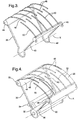
- a film sheet supporting frame is comprised of an upper, two sided support leg 38 and a lower, two sided support leg 40.
- the legs 38 and 40 are joined together by a pair of integral, C shaped rings 42, lying on the same central axis X.
- the legs 38 and 40 are disposed in a V shape just slightly wider than the separation of the pusher block rails 34 and 36.
- the two sides are joined by an integral cross member 44 and 46 respectively.
- Cantilerved from each cross member 44 and 46 are staggered, interleaved and equal length arcuate support fingers 48 and 50, which are also concentric to axis X.
- the two sets of fingers 48 and 50 overlap slightly at the ends. If the legs 38 and 40 are pushed toward one another, the base rings 42 compress, and the support fingers 48 and 50 overlap more, swinging freely past one another about the axis X.
- each roller 28 and 30 is journalled to a respective cross member 44 and 46, where it can turn freely about its own axis.
- the pusher block 32 is snapped within the base rings 42, and the rails 34 and 36 engage the outside of the support frame legs 38 and 40, holding them slightly inward from their free state separation, under a slight resilient compression in the base rings 42.
- the opposed biases of the spring loaded rollers 28 and 30 pull the film sheet 26 tightly over the support fingers 48 and 50, maintaining it in a convex semi cylinder concentric to the axis X.
- film valve 52 is installed within HVAC housing 10 with the co axis of the pusher block 32 and rings 42 disposed on the same axis X as the outlet opening arcuate edges 16. Consequently, the outer surface of the curved film sheet can be closely engaged flush against the outlet opening's perimeter foam strip 18, forming a snug compression seal and covering the entire opening.
- Fixed to the interior of housing 10 are a pair of opposed stops, upper stop 54 and lower stop 56 which, relative to the axis X, are disposed in the same general V shape as the pusher block side rails 34 and 36.
- the fixed stops 54 and 56 work in cooperation with the pusher block 32 which, in turn, is rotated back and forth about axis X by a rotary actuator motor 58, as is described in more detail below.
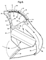
- the entire outlet opening is covered by the film sheet 26, edge to edge.
- Both temperature doors 22 and 24 are shown fully closed, and heater door 25 open, so that all of the inlet air is directed through heater core 20.
- the highly heated air is completely blocked from openings D and A by the film sheet 26, and directed entirely through the heater outlet opening H. This is typically referred to as the heat mode.
- the temperature doors 22 and 24 could, if desired, be open to an extent, to by pass some air around heater core 20 and consequently heat it less.
- the rotary valve 52 would not interfere with air flow past upper door 22 and down to opening H, since its wire frame construction is open.
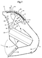
- valve 52 is shown rotated down and closed up sufficiently to uncover the upper defrost opening D, while the opening A below remains covered.
- the heater door 25 is closed, and both by pass doors 22 and 24 are closed, so that highly heated air through heater core 20 is directed all through D and to the windshield, the so called defrost mode.
- actuator motor 58 rotates the pusher block down, and the upper rail 34 pushes the upper frame leg 38 down, away from the upper fixed stop 54.
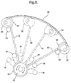
- the lower leg 40 is held in place by its contact with the lower fixed stop 56, so the lower pusher block 36 moves away and the upper leg 38 swings relatively toward it to compress the base rings 42, as shown in dotted line in Figure 5.
- the compressed base rings 42 would cause the upper frame leg 38 to swing back until it stopped against the upper fixed stop 54.
- the force in the compressed base rings 42 is strong enough to overcome the take up springs in the rollers 28 and 30, and the film sheet 26 would be wound off of the rollers 28 and 30 and back down onto the foam strip 18 in the same carpet like, non rubbing fashion.
- the opposed biases of the take up rollers 28 and 30 maintain film sheet taught against the fingers 48 and 50, and it is wound up and off of the foam strip 18 to uncover the opening A, without relative rubbing. It should be noted that the pusher block 32 could be rotated up or down through a lesser angle, uncovering either opening portion D or A correspondingly less, if desired. It should also be noted that neither roller 28 or 30 need overtravel past either straight edge 12 or 14 in order to fully uncover either opening portion A or D.
- rollers and legs could be stationary, with only the other roller and frame leg movable toward or away from it. This would be a less flexible system, but would still roll the film sheet down or up in the same non rubbing fashion. Only the movable leg would absolutely need a take up roller, in that case, although two spring biased take up rollers would better balance the tension in the sheet, even if one of the rollers was stationary.
- the actuator means could be designed to swing the support frame legs 38 and 40 directly in each direction, together and apart, as opposed to simply pushing them together, with the stored bias in the base rings 42 being used to swing them back apart.
- the embodiment shown is simple and cost effective, since the actuator 58 only needs to push each leg 38 and 40, not also pull it, and the fixed stops 54 and 56 are easily provided. Therefore, it will be understood that it is not intended to limit the invention to just the embodiment disclosed.
Landscapes
- Physics & Mathematics (AREA)
- Thermal Sciences (AREA)
- Engineering & Computer Science (AREA)
- Mechanical Engineering (AREA)
- Tents Or Canopies (AREA)
- Operating, Guiding And Securing Of Roll- Type Closing Members (AREA)
- Sealing Devices (AREA)
Abstract
Description
- This invention relates to automotive ventilation system valves in general, and specifically to a rotary film valve which maintains a convex, semi cylindrical shape in a self supporting manner, and which can moved along the interior surface of the perimeter of the housing opening without substantial relative rubbing.
- Automotive ventilation systems, often called HVAC systems (heating, ventilation and air conditioning systems) typically include a large, hollow housing located just behind the instrument panel of the vehicle interior. The housing includes the two heat exchangers, the cold evaporator core and hot heater core, as well as the various valves and doors that route intake air through or around the two to create outlet air of a desired temperature. Outlet openings in the housing and instrument panel direct the air up at the windshield, forwardly at the occupant, or downwardly at an occupants' feet. These openings are covered or uncovered by a suitable valve, as selected by the vehicle occupant. Typically, the outlet openings, in descending order of height, are called defrost, air conditioning, and heat, although air of any temperature may be directed through any of them.
- Different valves have been used to selectively cover and uncover the outlet openings, depending on the shape and orientation of the openings. In designs where the perimeters of the outlet openings are disposed in flat planes, it is relatively easy to use a so called film valve. In a film valve a belt or sheet of flexible film is stretched over rollers into one or more straight runs, which reside just behind the perimeter edges of the outlet opening or openings. As the film belt rolls around the rollers, back and forth, windows and solid portions in the belt alternately register with the outlet openings, covering and uncovering them. One drawback is the conflict between tightness of the seal and relative rubbing. If the surface of the belt is held flush against the interior surface of the perimeter edges of the outlet opening (usually against a foam seal that surrounds the opening), there is a frictional rubbing that retards the motion of the belt. If it is not held flush against the foam seal, there is not a complete blockage of air. Another known outlet valve is a rotary valve. With a rotary valve, the various outlet openings have perimeter edges disposed in semi cylindrical arcs and a semi cylindrical solid door swings up and down inside the housing to cover and uncover the openings. Seal rubbing is also a problem with a rotary valve. Another drawback with a solid rotary valve is that it must be designed with overtravel, that is, it must swing completely past the opening perimeter in order to completely uncover it, which detracts from compactness.
- Designs have been proposed in which a film belt is used to cover and uncover outlet openings which are curved, rather than flat. This requires additional structure since the natural orientation for a belt run is flat, the shape that it naturally takes on when stretched over a pair of rollers. As shown in USPN 5,105,730, the belt must be stretched over a rigid, concave curved supporting frame keep it in the necessary curved shape. This worsens the rubbing friction problem, since the film belt is now sandwiched between both the outlet opening's perimeter edge seal and the added supporting frame. An even earlier design, proposed for a domestic room air conditioner, appears to eliminate or reduce the rubbing by running a continuous, solid loop of film back and forth along a curved, rigid, but concave supporting frame. The frame is located behind a pair of side by side outlet openings, and the center of the belt loop is pinned to the frame, half way between the openings. Two rollers are spring biased apart inside the loop so as to keep it taught. The rollers roll back and forth to shift each half of the loop back and forth cover or uncover one or the other of the side by side openings. This design, while it largely eliminates rubbing, would not be adaptable to the automotive HVAC environment. The supporting frame that gives the belt run its shape must be concave or, at best, flat, and could not be convexly curved. In addition, the potential motion of the film belt back and forth is limited by the fact that it has to be pinned in the center to the frame. The rigid supporting frame needed in either design is, of course, an additional part that increases expense and takes up space within the housing.
- The invention provides a self supporting film valve that swings in a rotary motion, which needs no separate supporting frame to maintain it in a convexly curved shape, and which seals flush and tight to outlet opening without relative rubbing.
- In the preferred embodiment disclosed, a pair of film take up rollers is supported on a pair of resilient supporting frame legs, which radiate in a V shape from the axis of the same cylindrical envelope on which the outlet openings are oriented. The take up rollers are biased in opposite directions about their axes so as to continually wind the film up when the legs move together, or to wind the film out when the legs move apart. Interleaved arcuate support fingers on each supporting arm rest just behind the film sheet, disposed on a semi cylindrical arc concentric to the outlet opening. The opposing tensions in the take up rollers keep the film sheet taught against the fingers, thereby self supporting the film sheet into an arcuate shape that can be pressed flush against the edges of the opening to cover it tightly. When the film sheet is fully expanded, its arcuate width is sufficient to cover the whole opening, edge to edge. When the film sheet is contracted to any extent, the outlet opening is uncovered to the same extent. A pair of cooperating fixed stops and movable actuators allow either leg to be moved toward or away from the other leg, thereby contracting the film sheet as either roller is moved toward or away from an opposed straight edge of the outlet opening. Concurrently, the film sheet is wound up and away from the perimeter the outlet opening, or wound out and along the perimeter. Unlike conventional film valves and rigid rotary valves, as the outlet opening is covered and uncovered, there is no relative seal rubbing. Unlike solid, curved rotary valves, the rollers need not travel significantly past the edges of the opening in order to uncover it.
-
- Figure 1 is a perspective view of an automotive HVAC housing with a semi cylindrical outlet opening within which a rotary film valve according to the invention is incorporated;
- Figure 2 is a perspective view of the film sheet, take up rollers, and part of the actuation means;
- Figure 3 is a perspective view of the supporting frame alone;
- Figure 4 is a perspective view of the entire rotary film valve and part of the actuation means, removed from the housing;
- Figure 5 is a side view of the film valve, showing the fully extended, unwound condition in solid line, and showing two possible contracted positions is dotted line;
- Figure 6 is a view of the film valve installed within the housing and, as in Figure 5, completely wound out and expanded to its greatest arcuate width, so as to cover the entire outlet opening;
- Figure 7 is a view like Figure 6, but showing the film valve rotated down and partially wound up, so as to uncover an upper portion of the outlet opening; and
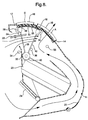
- Figure 8 is a view like Figure 6, but showing the film valve rotated up and partially wound up, so as to uncover the lower portion of the outlet opening.
-
- Referring first to Figures 1 and 6, the environment in which the rotary film valve of the invention is incorporated is an automotive HVAC housing, indicated generally at 10, which has a curved air outlet opening with a perimeter defined by opposed upper and lower flat or
straight edges curved edges 16, arrayed about a central axis X. The outlet opening is arbitrarily divided by a center rib into an upper, so called defrost opening D, and a lower, air conditioning opening A, but these lie on a common semi cylindrical envelope, and may be considered as one opening. A lower heater opening H rests well below the others, but is not directly covered or uncovered by the film valve of the invention. The interior surface of the perimeter of the outlet opening is comprised of a surroundingfoam strip 18.Housing 10 includes several conventional components, including aheater core 20 and upper (22) and lower (24) by pass doors, which direct inlet air through or aroundheater core 20 to determine its temperature. In addition, aconventional flapper door 25 opens and closes the heater outlet opening H. These doors do not directly form part of the rotary film valve of the invention, but cooperate with it, as they would with a conventional, solid rotary valve, to direct air of the desired temperature through the selected outlet opening D, A or H. The various components of the rotary film valve of the invention are described next. - Referring next to Figure 2, a thin, rectangular film sheet of mylar or other material sufficiently flexible to be repeatedly wound up and out is indicated at 26.
Film sheet 26 is long enough and wide enough such that, when oriented in a semi cylindrical envelope about X, it can cover the entire opening. The structure that actually keepssheet 26 in such a shape is described below. Each straight width edge ofsheet 26 is connected to an identical cylindrical take up roller, including anupper roller 28 andlower roller 30, each of which corresponds to a respective outlet openingstraight edge roller sheet 26 up if therollers rotary pusher block 32, also aligned on axis X.Pusher block 32 has a pair of identical,parallel rails outlet opening edges - Referring next to Figure 3, a film sheet supporting frame is comprised of an upper, two
sided support leg 38 and a lower, twosided support leg 40. At the base, thelegs legs leg integral cross member cross member arcuate support fingers support frame legs fingers legs support fingers - Referring next to Figure 4, the components described above are assembled together to complete the rotary film valve of the invention, indicated generally at 52. Each
roller respective cross member pusher block 32 is snapped within the base rings 42, and therails support frame legs rollers film sheet 26 tightly over thesupport fingers - Referring next to Figures 1, 5 and 6, film valve 52 is installed within
HVAC housing 10 with the co axis of thepusher block 32 and rings 42 disposed on the same axis X as the outlet opening arcuate edges 16. Consequently, the outer surface of the curved film sheet can be closely engaged flush against the outlet opening'sperimeter foam strip 18, forming a snug compression seal and covering the entire opening. Fixed to the interior ofhousing 10 are a pair of opposed stops,upper stop 54 andlower stop 56 which, relative to the axis X, are disposed in the same general V shape as the pusher block side rails 34 and 36. When film valve 52 is fully wound out and expanded, as shown in solid line in Figure 5, thestops legs pusher block 32 which, in turn, is rotated back and forth about axis X by arotary actuator motor 58, as is described in more detail below. In the Figure 6 position, the entire outlet opening is covered by thefilm sheet 26, edge to edge. Bothtemperature doors heater door 25 open, so that all of the inlet air is directed throughheater core 20. The highly heated air is completely blocked from openings D and A by thefilm sheet 26, and directed entirely through the heater outlet opening H. This is typically referred to as the heat mode. Thetemperature doors heater core 20 and consequently heat it less. The rotary valve 52 would not interfere with air flow pastupper door 22 and down to opening H, since its wire frame construction is open. - Referring next to Figures 5 and 7, the valve 52 is shown rotated down and closed up sufficiently to uncover the upper defrost opening D, while the opening A below remains covered. The
heater door 25 is closed, and both bypass doors heater core 20 is directed all through D and to the windshield, the so called defrost mode. In moving from the Figure 6 to the Figure 7 position,actuator motor 58 rotates the pusher block down, and theupper rail 34 pushes theupper frame leg 38 down, away from the upper fixedstop 54. Thelower leg 40 is held in place by its contact with the lower fixedstop 56, so thelower pusher block 36 moves away and theupper leg 38 swings relatively toward it to compress the base rings 42, as shown in dotted line in Figure 5. This compresses the base rings 42 and gives thelegs 38 and 40 a stored energy tending to move them back apart. Concurrently, the upper take uproller 28 moves down and away from the outlet opening's upperstraight edge 12, toward theother roller 30, and the interleaved sets of support fingers scissor past one another, overlapping more while remaining concentric to the axis X. The opposed biases of the two relatively approaching take uprollers film sheet 26 to be wound up, and keep it taught against thesupport fingers film sheet 26, as it winds up, is rolled up and away from thefoam strip 18 without relative rubbing, like a carpet being rolled up from a floor. If the process were to be reversed, andactuator 58 reversed to move theupper rail 34 back, then the compressed base rings 42 would cause theupper frame leg 38 to swing back until it stopped against the upper fixedstop 54. The force in the compressed base rings 42 is strong enough to overcome the take up springs in therollers film sheet 26 would be wound off of therollers foam strip 18 in the same carpet like, non rubbing fashion. - Referring next to Figures 5 and 8, the converse of the Figure 7 position is shown. The by
pass doors heater door 25 is closed, so that forced air by passes theheater core 20 and is directed up toward the underside of valve 52.Actuator 58 has rotatedblock 32 up, andlower rail 36 moves up to pushlower frame leg 40 up and away from the lower fixedstop 56.Upper frame leg 38 remains against the upper fixedstop 54, so thatlower leg 40 swings relatively toward it, as shown in dotted line in Figure 5, and the base rings 42 are again compressed. The lower take uproller 30 moves away from the lower outlet openingstraight edge 14, toward theupper roller 28, and thearcuate support fingers rollers fingers foam strip 18 to uncover the opening A, without relative rubbing. It should be noted that thepusher block 32 could be rotated up or down through a lesser angle, uncovering either opening portion D or A correspondingly less, if desired. It should also be noted that neitherroller straight edge - Variations in the preferred embodiment could be made. One or the other of the rollers and legs could be stationary, with only the other roller and frame leg movable toward or away from it. This would be a less flexible system, but would still roll the film sheet down or up in the same non rubbing fashion. Only the movable leg would absolutely need a take up roller, in that case, although two spring biased take up rollers would better balance the tension in the sheet, even if one of the rollers was stationary. The actuator means could be designed to swing the
support frame legs actuator 58 only needs to push eachleg
Claims (3)
- In an automotive heating, air conditioning and ventilation housing with an air opening oriented in a convex semi cylinder with first and second, opposed flat edges joined by opposed arcuate edges, the improvement comprising a self supporting, rotary film valve within said housing for selectively covering or uncovering said opening with substantially no rubbing against the surface of the interior perimeter of said opening, comprising:a thin film sheet having first and second opposed edges corresponding to the opposed first and second flat edges of said opening, and with an outer surface facing the interior perimeter of said opening and large enough in area to block said opening, said film sheet being sufficiently flexible to be rolled repeatedly up and out;a support frame having a support leg which is swingable in an are generally along said opening's arcuate edges and toward and away from one of said flat edges;a cylindrical roller attached to one of and supported on said support leg so as to be rotatable about its own axes and to swing concurrently along said opening's arcuate edges and toward and away from one of said opening's first and second flat edges;means continually biasing said roller to rotate about its own axis so as to concurrently roll said film sheet up and onto said roller as said roller move away from said opening's one flat edge;interleaved arcuate support fingers on said support frame leg and support frame matching the curvature of said opening's arcuate edges and continually tensioned against the inner surface of said film sheet so as to maintain said film sheet closely engaged with the surface of the interior perimeter of said opening; and,an actuator to selectively swing said support frame's support leg relatively away from said housing opening's one flat edge and roll said film sheet up and onto said roller, or to swing said frame support leg relatively toward said one flat edge and thereby roll said film sheet out and off of said roller;
whereby, as said actuator swings said roller back and forth, said film sheet is rolled up on said roller and away from said opening's interior perimeter or rolled off of said roller and onto said opening's interior perimeter to uncover or cover said opening without substantial rubbing of said film sheet against the surface of said opening's interior perimeter. - In an automotive heating, air conditioning and ventilation housing with an air opening oriented in a convex semi cylinder with first and second, opposed flat edges joined by opposed arcuate edges, the improvement comprising a self supporting, rotary film valve within said housing for selectively covering or uncovering said opening with substantially no rubbing against the surface of the interior perimeter of said opening, comprising:a thin film sheet having first and second opposed edges corresponding to the opposed first and second flat edges of said opening, and with an outer surface facing the interior perimeter of said opening and large enough in area to block said opening, said film sheet being sufficiently flexible to be rolled repeatedly up and out;a support frame having first and second legs swingable in an are generally along said opening's arcuate edges and toward and away from said flat edges;first and second cylindrical rollers attached to said film sheet's first and second edges and supported on said support frame's first and second legs so as to be rotatable about their own axes and to swing concurrently along said opening's arcuate edges and toward and away from said opening's first and second flat edges;means continually biasing said rollers to rotate about their own axes so as to concurrently roll said film sheet up and onto said rollers as said rollers move away from said opening's first and second flat edges;interleaved arcuate support fingers on said support frame legs matching the curvature of said opening's arcuate edges and continually tensioned against the inner surface of said film sheet so as to maintain said film sheet closely engaged with the surface of the interior perimeter of said opening; and,an actuator to selectively swing said support frame's first and second support legs relatively together and thereby move said rollers away from their respective housing opening flat edges and roll said film sheet up and onto said rollers, or to swing said frame support legs relatively together to move said rollers back toward their respective flat edges and thereby roll said film sheet out and off of said rollers;
whereby, as said actuator swings said rollers back and forth, said film sheet is rolled up on said rollers and away from said opening's interior perimeter or rolled off of said rollers and onto said opening's interior perimeter to uncover or cover said opening without substantial rubbing of said film sheet against the surface of said opening's interior perimeter. - In an automotive heating, air conditioning and ventilation housing with an air opening oriented in a convex semi cylinder with first and second, opposed flat edges joined by opposed arcuate edges, the improvement comprising a self supporting, rotary film valve within said housing for selectively covering or uncovering said opening with substantially no rubbing against the surface of the interior perimeter of said opening, comprising:a thin film sheet having first and second opposed edges corresponding to the opposed first and second flat edges of said opening, and with an outer surface facing the interior perimeter of said opening and large enough in area to block said opening, said film sheet being sufficiently flexible to be rolled repeatedly up and out;a support frame having first and second legs swingable in an arc generally along said opening's arcuate edges and toward and away from said flat edges;first and second cylindrical rollers attached to said film sheet's first and second edges and supported on said support frame's first and second legs so as to be rotatable about their own axes and to swing concurrently along said opening's arcuate edges and toward and away from said opening's first and second flat edges;means continually biasing said rollers to rotate about their own axes so as to concurrently roll said film sheet up and onto said rollers as said rollers move away from said opening's first and second flat edges;means continually biasing said supporting frame legs so as to move said rollers toward said opening's flat edges and thereby roll said film sheet out and off said roller in opposition to said rollers' bias;interleaved arcuate support fingers on said support frame legs matching the curvature of said opening's arcuate edges and continually tensioned against the inner surface of said film sheet so as to maintain said film sheet closely engaged with the surface of the interior perimeter of said opening; and,cooperating actuators and stops to selectively swing said support frame's first and second support legs in opposition to their bias and thereby move said rollers away from their respective housing opening flat edges and thereby roll said film sheet up and onto said rollers, or to release said frame support legs to move said rollers back toward their respective flat edges and thereby roll said film sheet out and off of said rollers;
whereby, as said actuator swings said rollers back and forth, said film sheet is rolled up on said rollers and away from said opening's interior perimeter or rolled off of said rollers and onto said opening's interior perimeter to uncover or cover said opening without substantial rubbing of said film sheet against the surface of said opening's interior perimeter.
Applications Claiming Priority (2)
| Application Number | Priority Date | Filing Date | Title |
|---|---|---|---|
| US62692 | 1998-04-20 | ||
| US09/062,692 US5885152A (en) | 1998-04-20 | 1998-04-20 | Automotive ventilation housing with self supporting film valve having a convex semi-cylindrical shape |
Publications (2)
| Publication Number | Publication Date |
|---|---|
| EP0952016A2 true EP0952016A2 (en) | 1999-10-27 |
| EP0952016A3 EP0952016A3 (en) | 2002-03-13 |
Family
ID=22044186
Family Applications (1)
| Application Number | Title | Priority Date | Filing Date |
|---|---|---|---|
| EP99200808A Withdrawn EP0952016A3 (en) | 1998-04-20 | 1999-03-16 | Automotive ventilation housing with self supporting film valve having a convex, semi-cylindrical shape |
Country Status (2)
| Country | Link |
|---|---|
| US (1) | US5885152A (en) |
| EP (1) | EP0952016A3 (en) |
Cited By (1)
| Publication number | Priority date | Publication date | Assignee | Title |
|---|---|---|---|---|
| DE102004013686A1 (en) * | 2004-03-18 | 2005-10-13 | Behr Gmbh & Co. Kg | Flow control device for controlling the flow rate of a fluid medium through a flow channel |
Families Citing this family (21)
| Publication number | Priority date | Publication date | Assignee | Title |
|---|---|---|---|---|
| DE10320340A1 (en) * | 2003-05-07 | 2004-12-09 | J. Eberspächer GmbH & Co. KG | Heating system for a vehicle |
| US7927684B2 (en) * | 2000-01-19 | 2011-04-19 | Saint-Gobain Performance Plastics Corporation | Low coefficient of friction polymer film |
| US7238102B2 (en) * | 2003-02-18 | 2007-07-03 | Delphi Technologies, Inc. | Heating, ventilation, and air conditioning system having a film valve and film for controlling air flow |
| US6431299B1 (en) * | 2000-04-05 | 2002-08-13 | Clark Equipment Company | Cooling air ducting for excavator |
| US6979258B2 (en) * | 2003-01-13 | 2005-12-27 | Delphi Technologies, Inc. | Point contact valve seats for film applications |
| JP2004345363A (en) * | 2003-03-18 | 2004-12-09 | Calsonic Kansei Corp | Air duct for vehicle |
| US6932691B1 (en) * | 2004-05-28 | 2005-08-23 | Macauto Industrial Co., Ltd. | Film valve assembly for a heating, ventilation and air conditioning system |
| US7371161B2 (en) * | 2004-08-27 | 2008-05-13 | Delphi Technologies, Inc. | Sliding film valve driven at edge |
| US7527551B2 (en) | 2004-08-27 | 2009-05-05 | Delphi Technologies, Inc. | Sliding valve, especially for heating, ventilation and air conditioning system |
| JP2006168584A (en) * | 2004-12-16 | 2006-06-29 | Denso Corp | Air passage changing device and vehicular air-conditioner |
| US7503234B2 (en) * | 2005-05-26 | 2009-03-17 | Delphi Technologies, Inc. | One lever tilt and telescope mechanism |
| US7530889B2 (en) * | 2005-09-30 | 2009-05-12 | Valeo Climate Control Corp. | Common HVAC doors |
| JP2007118753A (en) * | 2005-10-27 | 2007-05-17 | Denso Corp | Air passage opening and closing device |
| US20080146138A1 (en) * | 2006-12-15 | 2008-06-19 | Valeo Climate Control Corp. | Automotive HVAC with integral dividing wall connectors |
| US20090302544A1 (en) * | 2008-06-05 | 2009-12-10 | Pugh Jr Charles A | Air Duct Sealing System |
| US9180751B2 (en) * | 2011-08-18 | 2015-11-10 | Halla Visteon Climate Control Corporation | Air conditioner for vehicle |
| US20140273784A1 (en) * | 2013-03-13 | 2014-09-18 | Ford Global Technologies, Llc | Air extractor to reduce closing effort |
| US10052934B2 (en) * | 2013-05-10 | 2018-08-21 | Denso International America, Inc. | Convex grid shape to reduce turbulence under rotary door |
| US20160016458A1 (en) * | 2014-07-18 | 2016-01-21 | Caterpillar Inc. | Cabin Air System |
| JP6384253B2 (en) * | 2014-10-08 | 2018-09-05 | 株式会社デンソー | Passage opening and closing device and air conditioner provided with the same |
| CN111002787B (en) * | 2018-10-08 | 2023-04-11 | 翰昂汽车零部件有限公司 | Member with through hole and vehicle air conditioner provided with same |
Citations (1)
| Publication number | Priority date | Publication date | Assignee | Title |
|---|---|---|---|---|
| US5105730A (en) | 1990-12-17 | 1992-04-21 | Ford Motor Company | Air distribution apparatus for an automotive vehicle |
Family Cites Families (4)
| Publication number | Priority date | Publication date | Assignee | Title |
|---|---|---|---|---|
| US4084616A (en) * | 1976-09-30 | 1978-04-18 | Kta Corporation | Fluid proportioning device |
| JP2560753B2 (en) * | 1987-11-25 | 1996-12-04 | 日本電装株式会社 | Vehicle air conditioner |
| JPH03281423A (en) * | 1990-03-30 | 1991-12-12 | Nippondenso Co Ltd | Air conditioner |
| US5009392A (en) * | 1990-05-11 | 1991-04-23 | General Motors Corporation | Rotary air valve |
-
1998
- 1998-04-20 US US09/062,692 patent/US5885152A/en not_active Expired - Fee Related
-
1999
- 1999-03-16 EP EP99200808A patent/EP0952016A3/en not_active Withdrawn
Patent Citations (2)
| Publication number | Priority date | Publication date | Assignee | Title |
|---|---|---|---|---|
| US5105730A (en) | 1990-12-17 | 1992-04-21 | Ford Motor Company | Air distribution apparatus for an automotive vehicle |
| US5105730B1 (en) | 1990-12-17 | 1995-02-14 | Ford Motor Co | Air distribution apparatus for an automotive device |
Cited By (1)
| Publication number | Priority date | Publication date | Assignee | Title |
|---|---|---|---|---|
| DE102004013686A1 (en) * | 2004-03-18 | 2005-10-13 | Behr Gmbh & Co. Kg | Flow control device for controlling the flow rate of a fluid medium through a flow channel |
Also Published As
| Publication number | Publication date |
|---|---|
| US5885152A (en) | 1999-03-23 |
| EP0952016A3 (en) | 2002-03-13 |
Similar Documents
| Publication | Publication Date | Title |
|---|---|---|
| US5885152A (en) | Automotive ventilation housing with self supporting film valve having a convex semi-cylindrical shape | |
| US5009392A (en) | Rotary air valve | |
| JP3505834B2 (en) | Air passage switching device | |
| US4614152A (en) | Air induction system for automotive air-conditioner | |
| JP3646365B2 (en) | Automotive air conditioner | |
| US3672291A (en) | Ventilator unit | |
| US6852024B2 (en) | Air passage switching device and vehicle air conditioner using the same | |
| KR101011283B1 (en) | Door set for closing doorway of wall | |
| JPH08282258A (en) | Air conditioner for automobile | |
| US7246788B2 (en) | Roller belt cassette for use in a control device | |
| US5934361A (en) | Automotive heating and air conditioning assembly with improved air flow and temperature control | |
| US5931733A (en) | Air flow control device, in particular for a heating and/or air conditioning installation for a motor vehicle | |
| US9022844B2 (en) | Air conditioning apparatus | |
| CN113165478B (en) | Air supply device for motor vehicle | |
| KR970065038A (en) | Air flow control devices for automotive heating and / or air conditioning systems | |
| JP2512935B2 (en) | Air outlet switching mechanism for vehicle air conditioner | |
| US12287115B1 (en) | Smart vent/duct cover for controlling and cooling temperatures individual rooms | |
| US7241215B2 (en) | Fabric valve for vehicle climate control system | |
| US20040134691A1 (en) | Point contact valve seats for film applications | |
| JPH09290618A (en) | Inside-outside air selector of vehicular air conditioner | |
| JP2526854B2 (en) | Switchgear | |
| JP2570178B2 (en) | Switchgear | |
| JP2526853B2 (en) | Switchgear | |
| JP3966105B2 (en) | Air passage switching device | |
| JP2004148951A (en) | Air conditioner for automobile |
Legal Events
| Date | Code | Title | Description |
|---|---|---|---|
| PUAI | Public reference made under article 153(3) epc to a published international application that has entered the european phase |
Free format text: ORIGINAL CODE: 0009012 |
|
| AK | Designated contracting states |
Kind code of ref document: A2 Designated state(s): AT BE CH CY DE DK ES FI FR GB GR IE IT LI LU MC NL PT SE Kind code of ref document: A2 Designated state(s): DE FR GB |
|
| AX | Request for extension of the european patent |
Free format text: AL;LT;LV;MK;RO;SI |
|
| PUAL | Search report despatched |
Free format text: ORIGINAL CODE: 0009013 |
|
| AK | Designated contracting states |
Kind code of ref document: A3 Designated state(s): AT BE CH CY DE DK ES FI FR GB GR IE IT LI LU MC NL PT SE |
|
| AX | Request for extension of the european patent |
Free format text: AL;LT;LV;MK;RO;SI |
|
| 17P | Request for examination filed |
Effective date: 20020913 |
|
| AKX | Designation fees paid |
Free format text: DE FR GB |
|
| 17Q | First examination report despatched |
Effective date: 20030116 |
|
| STAA | Information on the status of an ep patent application or granted ep patent |
Free format text: STATUS: THE APPLICATION IS DEEMED TO BE WITHDRAWN |
|
| 18D | Application deemed to be withdrawn |
Effective date: 20030527 |