EP0952096A1 - Dispositif pour deplacer une charge sur un trajet de transport - Google Patents
Dispositif pour deplacer une charge sur un trajet de transport Download PDFInfo
- Publication number
- EP0952096A1 EP0952096A1 EP99107356A EP99107356A EP0952096A1 EP 0952096 A1 EP0952096 A1 EP 0952096A1 EP 99107356 A EP99107356 A EP 99107356A EP 99107356 A EP99107356 A EP 99107356A EP 0952096 A1 EP0952096 A1 EP 0952096A1
- Authority
- EP
- European Patent Office
- Prior art keywords
- drive
- conveyor roller
- base body
- conveyed
- arrangement according
- Prior art date
- Legal status (The legal status is an assumption and is not a legal conclusion. Google has not performed a legal analysis and makes no representation as to the accuracy of the status listed.)
- Granted
Links
- 239000000463 material Substances 0.000 claims abstract description 48
- 230000005540 biological transmission Effects 0.000 claims description 15
- 230000033001 locomotion Effects 0.000 claims description 9
- 230000001105 regulatory effect Effects 0.000 claims description 3
- 230000001276 controlling effect Effects 0.000 claims 1
- 238000010586 diagram Methods 0.000 description 2
- 229920001971 elastomer Polymers 0.000 description 2
- 239000000806 elastomer Substances 0.000 description 2
- 230000003993 interaction Effects 0.000 description 2
- 238000005096 rolling process Methods 0.000 description 2
- 230000001133 acceleration Effects 0.000 description 1
- 230000006399 behavior Effects 0.000 description 1
- 230000001934 delay Effects 0.000 description 1
- 230000001419 dependent effect Effects 0.000 description 1
- 238000001514 detection method Methods 0.000 description 1
- 230000006266 hibernation Effects 0.000 description 1
- 238000012423 maintenance Methods 0.000 description 1
- 230000006855 networking Effects 0.000 description 1
- 230000009467 reduction Effects 0.000 description 1
- 230000035882 stress Effects 0.000 description 1
- 230000008646 thermal stress Effects 0.000 description 1
Images



Classifications
-
- B—PERFORMING OPERATIONS; TRANSPORTING
- B65—CONVEYING; PACKING; STORING; HANDLING THIN OR FILAMENTARY MATERIAL
- B65G—TRANSPORT OR STORAGE DEVICES, e.g. CONVEYORS FOR LOADING OR TIPPING, SHOP CONVEYOR SYSTEMS OR PNEUMATIC TUBE CONVEYORS
- B65G13/00—Roller-ways
- B65G13/02—Roller-ways having driven rollers
- B65G13/06—Roller driving means
- B65G13/065—Roller driving means with displacement of the roller
Definitions
- the invention relates to an arrangement for moving a conveyed material along a Conveying level, especially for cargo loading systems in cargo holds, preferably from Airplanes.
- roller drives are used to transport loads in aircraft holds known, e.g. are extensively described in DE-PS 41 36 972.
- a Conveyor roller which is connected to a drive, controlled in its rolling motion, by sensors the position of a transport good above that driving the conveyor roller Detect the conveyor module and thus switch the drive on or off as required.
- a roller drive unit described in DE 39 11 214 C3 works similarly Drive motor, the drive axis of which is eccentric with respect to the roller inside the roller, the pressure force by means of an intermediate wheel running inside the roller Brake device branches.
- the pressure force is dependent on the rotary drive of the conveyor roller, whereby the pressure force is not on one suitable value can be set for the respective material to be conveyed. The consequences are increased Wear and a relatively short operating time.
- the invention has for its object a new way to move a To find goods to be conveyed with which, with little wear on the conveyor roller, a safe, reliable transport of the conveyed goods under the most diverse operating conditions is guaranteed.
- the object in an arrangement for moving a conveyed good along a conveyor plane that is powered by non-powered, for carrying and guiding a Conveying goods serving rollers is formed with a drivable conveyor roller is arranged between the idler rollers and a control electronics for Control of a drive driving the conveyor roller, solved in that the conveyor roller with a first drive and assigned first control unit for generating a traction force necessary to move the material to be conveyed along the conveying plane in Connection is established to a second drive with an assigned second control unit Generation of a sufficient pressing force of the conveyor roller against the material to be conveyed is present, and the control electronics the two independently controllable Coordinated drives.
- the conveyor roller in the form of a Hollow cylinder on a cylindrical base body rotatable about its axis of symmetry is mounted, the first drive via a gear located within the base body is connected to the conveyor roller, the base body by a parallel to it Eccentric axis extending axis of symmetry is rotatably mounted and the second drive with the base body for pivoting the base body about its eccentric axis and Pressing the conveyor roller is coupled to the material to be conveyed on the conveyor level.
- the control electronics advantageously contain a sensor unit for recognizing the material to be conveyed and a self-test facility that the two independent drives depending on a movement state of the movement detected at least by means of the internal sensor unit Conveyed goods controls.
- the transmission driving the conveyor roller advantageously has one in the eccentric axis of the cylindrical base body mounted pinion, which with the first drive in Connection is and is within the cylindrical body, and a radial between this pinion and the conveyor roller axially parallel driven output gear is present, which projects radially outwards over the base body and into a ring gear trained area of the conveyor roller engages.
- the transmission driving the conveyor roller between the first drive and the conveyor roller is, at least in a partial area, preferably designed as a planetary gear.
- the gear driving the conveyor roller also the planetary gear and the first drive arranged within the base body are, the sun gear of the planetary gear on the axis of symmetry of Base body is arranged and the planet gears formed in a ring gear Comb the area of the conveyor roller.
- the gearbox to swing out the body between the second drive and the Base body is also advantageous at least in a partial area as a planetary gear educated.
- the drive torque of at least the second drive for setting predeterminable pressure forces of the conveyor roller against the material to be conveyed is adjustable.
- first and the second drive are adjustable Servomotors are formed. Brushless ones are particularly suitable for this DC motors as the first and second drives.
- the self-test device contained in each drive unit is expedient with the Sensor unit in connection, depending on the detected standing or moving state of the conveyed goods alternatively first the second drive before switching on of the first or first the first drive before switching on the second via the Control units can be controlled.
- the self-test facility is for the purpose of the perfect overall function of a Systems of drive units advantageous over connections for the transmission of data obtained (such as pressure force, traction force, sensor function and Speed of rotation of the conveyor roller) in connection with a central unit.
- means for anti-slip control are expedient in the self-test device provided, from the central unit by means of the data obtained different drive units, knowing the exact distances of the Drive units and knowledge of the speed of rotation of the conveyor roller and real transport speed of the material to be conveyed an emerging slip through targeted Increasing the pressing force can be compensated.
- the invention is based on the general idea of turning and pressing of the conveyor rollers to use independent drives. This is for the Coordination of the two drives, an interaction with the sensor unit and one Control electronics are provided, the drives being controlled and regulated as required become. For the orderly interaction of several drive units Provide data exchange and control coordination with a central unit.
- the central components are Drive units 1, which are defined between driveless rollers 2 in each case Distances to each other are arranged distributed over the entire transport route. The exact distances between the drive units 1 are preferably not in one Central unit shown stored, the individual drive units 1 each Have connections 5 to this central unit.
- the rollers 2 have the essential carrier function of the in a cargo loading system Goods to be conveyed and define a so-called transport or conveyor level 3. Opposite this conveyor level 3 are the drivable conveyor rollers 4 of the drive units 1 in Hibernation, i.e. in the de-energized state of the conveyor roller drive, lowered so that it do not protrude beyond conveyor level 3 and thus in the case of manual transport of the material to be conveyed along the conveying plane 3 are not a hindrance.
- a drive unit 1 consists of a conveyor roller 4, a first drive 42, a second drive 43, a first control unit 421, one second control unit 431, a self-test device 6, a sensor 7 and the Connections 5 for networking with the central unit.
- the drives 42 and 43 are designed as brushless DC motors.
- This brushless DC motors the rotors of which contain permanent magnets very easy to control and regulate, namely in terms of speed and the force to be transmitted. This is done with the control units 421 and 431 assigned to them the first drive 42 designed in this way, which is used to generate the traction force for the Conveyed material is provided, both different engine speeds and thus different transport speeds as well as by simply reversing the polarity of one Realize the setpoint in the opposite direction of rotation.
- the second drive 43 which is used to generate the pressing force (conveying roller 4 against conveyed goods) is provided, after the detection of a conveyed good by the sensor 7 switched on and thus lifts the conveyor roller 4 via a gearbox until it reaches desired pressure force and remains in this position.
- the use of the brushless DC motor especially because it is characterized by a low Power consumption distinguished after the desired pressure force has been reached and the DC motor in this position to ensure a constant Contact pressure persists.
- the low power consumption results in a low one Temperature increase of the second drive 43, which in turn leads to a low Thermal stress leads.
- the two drives 42 and 43 can be controlled independently of one another, it is Particularly advantageous if one detected by the sensor 7 above the drive unit 1 stationary material to be conveyed, first the second drive 43 is switched on and, after the necessary pressure force has been reached, the first Drive 42 is switched on, which then generates the necessary traction force. If that Conveyed goods have been recognized as already in motion and are to be transported onwards first the first drive 42 is switched on to generate the necessary traction force and then only the second drive 43 to achieve the maximum desired Pressing force. This minimizes wear on the conveyor roller 4.
- the proposed cargo loading system with the invention Drive units 1 to a so-called anti-slip control.
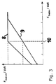
- the speed specified by the first drive 42 is significantly greater than that actual transport speed of the conveyed goods. Compensation is achieved by increasing the pressure force.
- the regulation expediently takes over the central unit, since the necessary information is brought together in it, such as distances between the drive units 1, set speed of the conveyor roller 4 and Magnitude of the pressing force that is generated by the second drive 43.
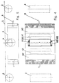
- FIGS. 4 and 5 again show a drive unit 1 as part of a conveyor shown with driveless rollers 2 and drivable conveyor roller 4.
- the driveless rollers 2 in dash-dotted lines Lines shown.
- the distance between successive conveyor rollers 4 is to select application-specifically such that a conveyed good is always from at least one drivable conveyor roller 4 is contacted. Worn by weight the material to be conveyed is essentially driven by the idler rollers 2.
- Prerequisite for an active funding status driven conveyor rollers 4 is that there is a material to be conveyed for the Conveyor roller 4 contactable surface is located above the conveyor roller 4. The reason, which is why the drivable conveyor roller 4 in the inactive state below the conveyor level 3 should lie, otherwise, the material to be conveyed to the level 3 outstanding conveyor roller 4 would hit if the material to be conveyed along the Conveyor level 3 is moved towards the drivable conveyor roller 4, or a rolling obstacle represents if the conveyor roller 4 in the inactive state at the level of the conveyor level 3 lies.
- the conveyor rollers 4 on the projecting from the rollers 2 spanned conveyor level 3, controlled transverse movements of the material to be conveyed relative to the alignment of the rollers 2, wherein in In this case, the conveyor rollers 4 in elements to be supported in spatially limited areas become.
- the conveyor rollers 4 are different aligned and have smaller distances from each other than the dimensions of the conveyed goods, at least three conveyor rollers 4 not lying along a straight line at the same time must attack under the material being conveyed.
- the structure of the drive units 1 is described below using a diagram according to FIG. 4 explained.
- the drivable conveyor roller 4 is rotatable on a cylindrical base body 41 stored.
- This base body 41 is eccentric about its axis of symmetry 411 Eccentric axis 412 rotatably mounted, the base body 41 with respect to the Eccentric axis 412 fixed to the housing in an eccentric counter bearing 432 vertical (from the Drawing plane out) is pivotally mounted.
- the conveyor roller 4 is on her Circumferential surface formed as an elastomer or coated with an elastomer material.
- the rotational movement of the drivable conveyor roller 4 is controlled by a first drive 42 causes that with its own control unit 421 (control and power electronics) connected is.
- the driving force is supplied by the first drive 42 via (not in FIG. 4 shown) gear transmission of the conveyor roller 4 fed.
- the drive 42 can in Connection with the control unit 421, the conveyor roller 4 in opposite Directions are driven.
- the start of the conveyor roller 4 can accelerate be regulated, which in particular allows a gentle start.
- the material to be conveyed can be reduced by reducing the speed of rotation of the material to be conveyed contacting conveyor roller 4 in particular also be braked in a defined manner. Also in The material to be conveyed can come to a standstill due to the pressure force exerted by the second drive 43 applied, remain intact, thereby securing the goods against moving is.
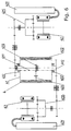
- Fig. 6 shows the drivable conveyor roller 4 in a hatched sectional view.
- the conveyor roller 4 is on the outer surface of a cylindrical base body 41 around it Axis of symmetry 411 rotatably mounted.
- This base body 41 is in turn one its axis of symmetry 411 rotatably eccentric eccentric axis 412, the Base body 41 with respect to the eccentric axis 412 fixed to the housing in one Eccentric counter bearing 432 is vertically pivoted.
- the rotational movement of the drivable conveyor roller 4 is controlled by a first drive 42 causes, which is connected to its own control unit 421 and outside the Base body 41 is located.
- the driving force is from the first drive 42 Gear transmission fed to the conveyor roller 4, the first part of the gear transmission being a planetary gear 425 is formed.
- the transmission between the planetary gear 425 and the conveyor roller 4 has a shaft mounted in the eccentric axis 412 on the base body 41 with a pinion 422.
- the pinion 422 acts on an output gear 423 via spur gear teeth, this in turn - reaching radially outward through the base body 41 - the conveyor roller 4 drives.
- the driven gear 423 meshes in an area designed as a ring gear 424 the conveyor roller 4.
- the rotation of the base body 41 about its eccentric axis 412 causes the second Drive 43, which in turn has its own control unit 431 (control and Power electronics) is connected.
- the transmission of the drive energy of the drive 43 is also carried out directly via a gear transmission, inter alia with a drive 43 subordinate planetary gear 433.
- FIG. 7 Another advantageous kinematic embodiment of the invention Drive unit 1 is shown in FIG. 7. This differs from the scheme in Fig. 6 only in the spatial arrangement of the first first drive 42. This is here as often in the prior art preferably housed within the conveyor roller 4.
- the A special feature in this example is that the drive shaft inside the Base body 41 was moved from the eccentric axis 412 into the axis of symmetry 411 and the pinion 422 (from FIG. 6) here as a sun gear which at the same time as the drive 42 inside the conveyor roller 4 arranged planetary gear 425 is executed.
- the planet gears of the Planetary gear 425 also engage, as in FIG.
- the conveying speed and the conveying conditions (such as weight and coefficient of friction) of the Conveyed goods are both jerky power transmissions and slip between the Conveyor roller 4 and the material to be conveyed avoided, causing wear on the material to be conveyed contacting elastomeric surface material of the conveyor roller 4 significantly reduced becomes.
- Such a reduction in wear is only after an extremely long time Operating times a replacement of the worn conveyor roller upper material or Drive unit necessary.
Landscapes
- Engineering & Computer Science (AREA)
- Mechanical Engineering (AREA)
- Rollers For Roller Conveyors For Transfer (AREA)
- Control Of Conveyors (AREA)
- Attitude Control For Articles On Conveyors (AREA)
- Feeding Of Articles To Conveyors (AREA)
- Branching, Merging, And Special Transfer Between Conveyors (AREA)
- Delivering By Means Of Belts And Rollers (AREA)
Applications Claiming Priority (4)
| Application Number | Priority Date | Filing Date | Title |
|---|---|---|---|
| DE1998117713 DE19817713A1 (de) | 1998-04-21 | 1998-04-21 | Förderrollen-Antrieb |
| DE19817713 | 1998-04-21 | ||
| DE19818522 | 1998-04-24 | ||
| DE1998118522 DE19818522A1 (de) | 1998-04-24 | 1998-04-24 | Frachtladesystem |
Publications (2)
| Publication Number | Publication Date |
|---|---|
| EP0952096A1 true EP0952096A1 (fr) | 1999-10-27 |
| EP0952096B1 EP0952096B1 (fr) | 2002-11-13 |
Family
ID=26045649
Family Applications (1)
| Application Number | Title | Priority Date | Filing Date |
|---|---|---|---|
| EP99107356A Expired - Lifetime EP0952096B1 (fr) | 1998-04-21 | 1999-04-21 | Dispositif pour deplacer une charge sur un trajet de transport |
Country Status (4)
| Country | Link |
|---|---|
| US (1) | US6279730B1 (fr) |
| EP (1) | EP0952096B1 (fr) |
| AT (1) | ATE227684T1 (fr) |
| DE (1) | DE59903371D1 (fr) |
Cited By (1)
| Publication number | Priority date | Publication date | Assignee | Title |
|---|---|---|---|---|
| US7014038B2 (en) | 2001-03-29 | 2006-03-21 | Ancra International, Llc | Cargo power drive unit |
Families Citing this family (7)
| Publication number | Priority date | Publication date | Assignee | Title |
|---|---|---|---|---|
| EP1620312B1 (fr) * | 2003-05-02 | 2007-09-19 | Ancra International, Llc | Bloc d'entrainement de charge orientable /escamotable |
| TWD107385S1 (zh) * | 2004-07-20 | 2005-11-01 | 東京威力科創股份有限公司 | 晶圓搬運機 |
| DE102005008443B4 (de) * | 2005-02-24 | 2009-06-18 | Airbus Deutschland Gmbh | Ladevorrichtung zum zumindest teilautomatischen Beladen und Entladen eines Frachtraums eines Verkehrsmittels |
| DE102005030058A1 (de) * | 2005-06-27 | 2007-01-04 | Wittenstein Ag | Vorrichtung zum Transportieren von Frachtgut |
| US8109702B2 (en) * | 2008-08-28 | 2012-02-07 | Goodrich Corporation | Attenuated cargo caster |
| DE102011000820B4 (de) * | 2011-02-18 | 2012-09-06 | Telair International Gmbh | Frachtladesystem und Verfahren zur Steuerung einer Vielzahl von Frachtfördereinrichtungen |
| US9925906B1 (en) * | 2016-09-23 | 2018-03-27 | Philip L. Hoy | Self-unloading pipe trailer |
Citations (8)
| Publication number | Priority date | Publication date | Assignee | Title |
|---|---|---|---|---|
| DE3911214A1 (de) | 1989-04-06 | 1990-10-11 | Electro Pneumatic Int | Rollenantriebseinheit |
| EP0481587A1 (fr) * | 1990-10-18 | 1992-04-22 | Teleflex Incorporated | Unité d'entraînement avec deux moteurs pour marchandises ordinaires |
| EP0512672A1 (fr) * | 1991-05-03 | 1992-11-11 | Teleflex Incorporated | Système de contrôle de chargement de fret pour avion |
| DE4136972A1 (de) | 1991-11-11 | 1993-05-13 | Airbus Gmbh | Vorrichtung zum positionieren von lasten in flugzeugfrachtraeumen |
| GB2291848A (en) * | 1994-08-04 | 1996-02-07 | Telair Int Cargo Sys Gmbh | Conveyor for loading and unloading cargo |
| US5547069A (en) * | 1991-01-30 | 1996-08-20 | Teleflex Incorporated | Modular cargo drive unit for a conveyor |
| DE19608236C1 (de) | 1996-03-04 | 1997-05-22 | Jarl Dipl Ing Sundseth | Rollenantriebseinheit |
| US5803234A (en) * | 1996-03-01 | 1998-09-08 | Ancra International Corporation | Roller drive system for vehicle conveyor |
Family Cites Families (7)
| Publication number | Priority date | Publication date | Assignee | Title |
|---|---|---|---|---|
| DE6910760U (de) | 1969-03-18 | 1970-09-10 | Noltemeyer Ludwig Fr | Vorrichtung zum vorbehandeln einer schlauchfolie |
| US3709450A (en) * | 1970-12-11 | 1973-01-09 | Boeing Co | Cargo loading system for aircraft |
| US3978975A (en) | 1975-06-30 | 1976-09-07 | The Boeing Company | Cargo power drive unit |
| US4589542A (en) | 1983-12-19 | 1986-05-20 | The Boeing Company | Cargo drive unit |
| US5183150A (en) * | 1991-12-13 | 1993-02-02 | Allied-Signal Inc. | Cargo drive unit with a hysteresis coupling |
| DE19807229C2 (de) | 1998-02-20 | 1999-12-23 | Telair Int Gmbh | Rollenantriebseinheit und Ladesystem mit Sensoren und einer Steuerlogik, insbesondere zum motorgetriebenen Anheben und Absenken der Antriebsrollen von Rollenantriebseinheiten |
| DE19807230B4 (de) * | 1998-02-20 | 2004-05-27 | Telair International Gmbh | Antriebsrolleneinheit |
-
1999
- 1999-04-20 US US09/294,478 patent/US6279730B1/en not_active Expired - Fee Related
- 1999-04-21 DE DE59903371T patent/DE59903371D1/de not_active Expired - Lifetime
- 1999-04-21 EP EP99107356A patent/EP0952096B1/fr not_active Expired - Lifetime
- 1999-04-21 AT AT99107356T patent/ATE227684T1/de not_active IP Right Cessation
Patent Citations (8)
| Publication number | Priority date | Publication date | Assignee | Title |
|---|---|---|---|---|
| DE3911214A1 (de) | 1989-04-06 | 1990-10-11 | Electro Pneumatic Int | Rollenantriebseinheit |
| EP0481587A1 (fr) * | 1990-10-18 | 1992-04-22 | Teleflex Incorporated | Unité d'entraînement avec deux moteurs pour marchandises ordinaires |
| US5547069A (en) * | 1991-01-30 | 1996-08-20 | Teleflex Incorporated | Modular cargo drive unit for a conveyor |
| EP0512672A1 (fr) * | 1991-05-03 | 1992-11-11 | Teleflex Incorporated | Système de contrôle de chargement de fret pour avion |
| DE4136972A1 (de) | 1991-11-11 | 1993-05-13 | Airbus Gmbh | Vorrichtung zum positionieren von lasten in flugzeugfrachtraeumen |
| GB2291848A (en) * | 1994-08-04 | 1996-02-07 | Telair Int Cargo Sys Gmbh | Conveyor for loading and unloading cargo |
| US5803234A (en) * | 1996-03-01 | 1998-09-08 | Ancra International Corporation | Roller drive system for vehicle conveyor |
| DE19608236C1 (de) | 1996-03-04 | 1997-05-22 | Jarl Dipl Ing Sundseth | Rollenantriebseinheit |
Cited By (1)
| Publication number | Priority date | Publication date | Assignee | Title |
|---|---|---|---|---|
| US7014038B2 (en) | 2001-03-29 | 2006-03-21 | Ancra International, Llc | Cargo power drive unit |
Also Published As
| Publication number | Publication date |
|---|---|
| ATE227684T1 (de) | 2002-11-15 |
| US6279730B1 (en) | 2001-08-28 |
| EP0952096B1 (fr) | 2002-11-13 |
| DE59903371D1 (de) | 2002-12-19 |
Similar Documents
| Publication | Publication Date | Title |
|---|---|---|
| EP2736822B1 (fr) | Dispositif transporteur doté d'un organe transporteur s'étendant à plat | |
| DE602004009053T2 (de) | Lenkbare /einziehbare frachtkraftantriebseinheit | |
| DE69301361T2 (de) | Antriebseinrichtung für eine mechanische Presse | |
| DE69031613T2 (de) | Gelenkstruktur für einen beintragenden Gehroboter | |
| DE4102424C3 (de) | Antriebsrolleneinheit | |
| DE68920795T2 (de) | Transportvorrichtung. | |
| DE3429098C2 (fr) | ||
| DE3784980T2 (de) | Kurzhubtransferpresse mit automatischer vorschubeinrichtung. | |
| EP3412604A1 (fr) | Système d'entraînement pour une bande transporteuse, procédé d'entraînement d'une bande transporteuse, bande transporteuse, dispositif de commande et produit-programme d'ordinateur | |
| EP2837545A2 (fr) | Unité de transport et système de transport doté de telles unités de transport | |
| EP0952096A1 (fr) | Dispositif pour deplacer une charge sur un trajet de transport | |
| DE102013016707A1 (de) | Transportvorrichtung und Bestückvorrichtung damit | |
| EP3119714A1 (fr) | Ascenseur | |
| DE3408351A1 (de) | Tochterdrehvorrichtung fuer mechanische greifer eines foerderkrans | |
| DE3346035A1 (de) | Werkstueckfoerdereinrichtung | |
| WO2015181309A1 (fr) | Système de bande transporteuse avec entraînement de bande transporteuse décentralisé et procédé de fonctionnement du système de bande transporteuse | |
| DE19900461C2 (de) | Transportvorrichtung | |
| CH706033A1 (de) | Fördereinrichtung mit einem flächig ausgedehnten Förderorgan. | |
| WO2024121051A1 (fr) | Unité de transport de support de charge avec agencement de rouleau compact | |
| DE19704702B4 (de) | Elimination von Lose-Effekten in Druckmaschinen | |
| DE10051758B4 (de) | Positioniervorrichtung und deren Arbeitsverfahren | |
| DE102021110085A1 (de) | Fahrantrieb | |
| DE8812338U1 (de) | Fördervorrichtung | |
| DE20022495U1 (de) | Positioniervorrichtung | |
| DE1047629B (de) | Differential-Regeleinrichtung |
Legal Events
| Date | Code | Title | Description |
|---|---|---|---|
| PUAI | Public reference made under article 153(3) epc to a published international application that has entered the european phase |
Free format text: ORIGINAL CODE: 0009012 |
|
| AK | Designated contracting states |
Kind code of ref document: A1 Designated state(s): AT DE ES FR GB IT |
|
| AX | Request for extension of the european patent |
Free format text: AL;LT;LV;MK;RO;SI |
|
| 17P | Request for examination filed |
Effective date: 19991224 |
|
| AKX | Designation fees paid |
Free format text: AT DE FR GB |
|
| RBV | Designated contracting states (corrected) |
Designated state(s): AT BE CH DE FR GB LI |
|
| RBV | Designated contracting states (corrected) |
Designated state(s): AT DE ES FR GB IT |
|
| 17Q | First examination report despatched |
Effective date: 20000801 |
|
| RBV | Designated contracting states (corrected) |
Designated state(s): DE ES FR GB IT |
|
| RBV | Designated contracting states (corrected) |
Designated state(s): AT DE ES FR GB IT |
|
| GRAG | Despatch of communication of intention to grant |
Free format text: ORIGINAL CODE: EPIDOS AGRA |
|
| RAP1 | Party data changed (applicant data changed or rights of an application transferred) |
Owner name: WITTENSTEIN MOTION CONTROL GMBH Owner name: JENOPTIK AKTIENGESELLSCHAFT |
|
| GRAG | Despatch of communication of intention to grant |
Free format text: ORIGINAL CODE: EPIDOS AGRA |
|
| GRAH | Despatch of communication of intention to grant a patent |
Free format text: ORIGINAL CODE: EPIDOS IGRA |
|
| GRAH | Despatch of communication of intention to grant a patent |
Free format text: ORIGINAL CODE: EPIDOS IGRA |
|
| GRAA | (expected) grant |
Free format text: ORIGINAL CODE: 0009210 |
|
| AK | Designated contracting states |
Kind code of ref document: B1 Designated state(s): AT DE ES FR GB IT |
|
| PG25 | Lapsed in a contracting state [announced via postgrant information from national office to epo] |
Ref country code: IT Free format text: LAPSE BECAUSE OF FAILURE TO SUBMIT A TRANSLATION OF THE DESCRIPTION OR TO PAY THE FEE WITHIN THE PRESCRIBED TIME-LIMIT;WARNING: LAPSES OF ITALIAN PATENTS WITH EFFECTIVE DATE BEFORE 2007 MAY HAVE OCCURRED AT ANY TIME BEFORE 2007. THE CORRECT EFFECTIVE DATE MAY BE DIFFERENT FROM THE ONE RECORDED. Effective date: 20021113 |
|
| REF | Corresponds to: |
Ref document number: 227684 Country of ref document: AT Date of ref document: 20021115 Kind code of ref document: T |
|
| REG | Reference to a national code |
Ref country code: GB Ref legal event code: FG4D Free format text: NOT ENGLISH |
|
| GBT | Gb: translation of ep patent filed (gb section 77(6)(a)/1977) |
Effective date: 20021113 |
|
| REF | Corresponds to: |
Ref document number: 59903371 Country of ref document: DE Date of ref document: 20021219 |
|
| ET | Fr: translation filed | ||
| PG25 | Lapsed in a contracting state [announced via postgrant information from national office to epo] |
Ref country code: AT Free format text: LAPSE BECAUSE OF NON-PAYMENT OF DUE FEES Effective date: 20030421 |
|
| PG25 | Lapsed in a contracting state [announced via postgrant information from national office to epo] |
Ref country code: ES Free format text: LAPSE BECAUSE OF FAILURE TO SUBMIT A TRANSLATION OF THE DESCRIPTION OR TO PAY THE FEE WITHIN THE PRESCRIBED TIME-LIMIT Effective date: 20030529 |
|
| PLBE | No opposition filed within time limit |
Free format text: ORIGINAL CODE: 0009261 |
|
| STAA | Information on the status of an ep patent application or granted ep patent |
Free format text: STATUS: NO OPPOSITION FILED WITHIN TIME LIMIT |
|
| 26N | No opposition filed |
Effective date: 20030814 |
|
| REG | Reference to a national code |
Ref country code: GB Ref legal event code: 732E |
|
| REG | Reference to a national code |
Ref country code: FR Ref legal event code: TP |
|
| PGFP | Annual fee paid to national office [announced via postgrant information from national office to epo] |
Ref country code: FR Payment date: 20100506 Year of fee payment: 12 |
|
| PGFP | Annual fee paid to national office [announced via postgrant information from national office to epo] |
Ref country code: GB Payment date: 20100420 Year of fee payment: 12 Ref country code: DE Payment date: 20100629 Year of fee payment: 12 |
|
| REG | Reference to a national code |
Ref country code: DE Ref legal event code: R119 Ref document number: 59903371 Country of ref document: DE |
|
| REG | Reference to a national code |
Ref country code: DE Ref legal event code: R119 Ref document number: 59903371 Country of ref document: DE |
|
| GBPC | Gb: european patent ceased through non-payment of renewal fee |
Effective date: 20110421 |
|
| REG | Reference to a national code |
Ref country code: FR Ref legal event code: ST Effective date: 20111230 |
|
| PG25 | Lapsed in a contracting state [announced via postgrant information from national office to epo] |
Ref country code: FR Free format text: LAPSE BECAUSE OF NON-PAYMENT OF DUE FEES Effective date: 20110502 |
|
| PG25 | Lapsed in a contracting state [announced via postgrant information from national office to epo] |
Ref country code: GB Free format text: LAPSE BECAUSE OF NON-PAYMENT OF DUE FEES Effective date: 20110421 |
|
| PG25 | Lapsed in a contracting state [announced via postgrant information from national office to epo] |
Ref country code: DE Free format text: LAPSE BECAUSE OF NON-PAYMENT OF DUE FEES Effective date: 20111031 |