EP0952253B1 - Vorrichtung zum Auffangen von Flüssigkeiten im Schienenbereich - Google Patents
Vorrichtung zum Auffangen von Flüssigkeiten im Schienenbereich Download PDFInfo
- Publication number
- EP0952253B1 EP0952253B1 EP19990106940 EP99106940A EP0952253B1 EP 0952253 B1 EP0952253 B1 EP 0952253B1 EP 19990106940 EP19990106940 EP 19990106940 EP 99106940 A EP99106940 A EP 99106940A EP 0952253 B1 EP0952253 B1 EP 0952253B1
- Authority
- EP
- European Patent Office
- Prior art keywords
- drain
- pans
- pan
- transverse
- adjacent
- Prior art date
- Legal status (The legal status is an assumption and is not a legal conclusion. Google has not performed a legal analysis and makes no representation as to the accuracy of the status listed.)
- Expired - Lifetime
Links
- 239000007788 liquid Substances 0.000 title claims description 10
- 238000007789 sealing Methods 0.000 claims description 33
- 239000000463 material Substances 0.000 claims description 8
- 239000012530 fluid Substances 0.000 claims description 6
- 239000004033 plastic Substances 0.000 claims description 5
- 229920003023 plastic Polymers 0.000 claims description 5
- 229920001903 high density polyethylene Polymers 0.000 claims description 4
- 239000004700 high-density polyethylene Substances 0.000 claims description 4
- 239000012858 resilient material Substances 0.000 claims description 3
- 239000011344 liquid material Substances 0.000 claims 1
- 239000011343 solid material Substances 0.000 claims 1
- 238000009434 installation Methods 0.000 description 8
- 230000008602 contraction Effects 0.000 description 4
- 239000004576 sand Substances 0.000 description 4
- 238000000034 method Methods 0.000 description 3
- 239000002991 molded plastic Substances 0.000 description 3
- 238000005452 bending Methods 0.000 description 2
- 238000010276 construction Methods 0.000 description 2
- 239000002245 particle Substances 0.000 description 2
- 239000007787 solid Substances 0.000 description 2
- 239000004698 Polyethylene Substances 0.000 description 1
- 239000011152 fibreglass Substances 0.000 description 1
- 238000003780 insertion Methods 0.000 description 1
- 230000037431 insertion Effects 0.000 description 1
- 239000003562 lightweight material Substances 0.000 description 1
- 230000013011 mating Effects 0.000 description 1
- 239000002184 metal Substances 0.000 description 1
- -1 polyethylene Polymers 0.000 description 1
- 229920000573 polyethylene Polymers 0.000 description 1
- 238000005086 pumping Methods 0.000 description 1
- 230000002787 reinforcement Effects 0.000 description 1
- 230000000284 resting effect Effects 0.000 description 1
- 239000011435 rock Substances 0.000 description 1
Images



Classifications
-
- E—FIXED CONSTRUCTIONS
- E01—CONSTRUCTION OF ROADS, RAILWAYS, OR BRIDGES
- E01B—PERMANENT WAY; PERMANENT-WAY TOOLS; MACHINES FOR MAKING RAILWAYS OF ALL KINDS
- E01B19/00—Protection of permanent way against development of dust or against the effect of wind, sun, frost, or corrosion; Means to reduce development of noise
- E01B19/006—Means for protecting the underground against spillage
-
- E—FIXED CONSTRUCTIONS
- E01—CONSTRUCTION OF ROADS, RAILWAYS, OR BRIDGES
- E01B—PERMANENT WAY; PERMANENT-WAY TOOLS; MACHINES FOR MAKING RAILWAYS OF ALL KINDS
- E01B1/00—Ballastway; Other means for supporting the sleepers or the track; Drainage of the ballastway
- E01B1/008—Drainage of track
Definitions
- This invention relates to a system for collecting liquid spillage having a pair of rails supported on crossties, said system comprising a plurality of drain pans of plastic material which are positioned end to end along the sides of the rails and between the rails, which are supported on said crossties, and which end adjacent to the rails beneath their heads, enclosed transverse elongated drain conduits positioned between pairs of adjacent crossties below said drain pans and having an upper surface spaced vertically from said drain pans, pairs of associated spaced openings in said drain pans and said transverse drain conduits, and drain pipes mounted between each of the pairs of aligned openings to provide flow passages from said drain pans to said enclosed transverse drain conduits.
- This system for collecting liquid spillage has a plurality of center pans and side pans.
- Vertical drain conduits extend from the pans into an enclosed transverse drain conduit for drainage.
- the transverse drain conduit empties into a collection receptacle. While the pans are formed of a molded plastic material, separate vertical drains are connected to the bottom of the pans. Further, while side edges of the pans are positioned adjacent the vertical web of the rails, a separate caulking material is used to provide sealing against the rails.
- the rigid vertical drain conduits are threaded into openings in the pans and in the enclosed transverse drain conduit.
- each drain pan is formed in one piece of a homogeneous lightweight resilient material, that each drain pan has a drain pipe integrally moulded therewith and extending downwardly therefrom for being inserted into the associated upper opening in a transverse drain conduit, that a resilient annular sealing member is positioned about each of said upper openings in said transverse drain conduits for receiving the associated drain pipe for providing a generally fluid tight seal thereat and permitting limited movement of the drain pans relative to the transverse drain conduit, and that each drain pan has one upwardly extending inclined resilient side flange or a pair of them for engaging the rail(s) beneath their head(s) in a snap-fit sealing relation.
- the collection structure according to the invention includes a plurality of center and side pans molded to shape from a resilient plastic material, such as high density polyethylene.
- the resilient center pans between rails have a pair of upwardly extending inclined side flanges which fit beneath the heads of the rails in sealing relation with the rails without any additional sealing members.
- a downwardly extending tubular drain pipe is molded onto each pan and fits within an enclosed transverse drain conduit positioned between a pair of crossties beneath the rails.
- the transverse drain conduit has an upper opening receiving each vertical drain pipe and a resilient annular seal about the upper opening receives the vertical drain pipe to provide a resilient sealing relation and to position the pans accurately.
- the outer ends of the pans in one transverse row have outwardly extending end flanges which lap end flanges on an adjacent transverse row of pans arranged in end to end relation.
- Fasteners connect the lapping end flanges of adjacent transverse rows together to permit limited relative longitudinal movement which may result from temperature expansion or contraction, for example.
- a preferred assembly method includes the insertion of center pans between the rails with one resilient side flange positioned beneath the rail against the vertical web of the rail under the head of the rail with the pan being inclined upwardly from the rail.
- the inclined pan is then pivoted downwardly with the bottom of the center pan resting against the crossties and the opposite resilient side flange in contact relation with the upper surface of the rail.
- the opposite resilient side flange is forced by a suitable tool downwardly beneath the head of the rail where it snaps outwardly against the vertical web of the rail in sealing relation thereto.
- a downwardly extending integral drain pipe molded on each of the pans is vertically aligned with the lower receiving opening in the transverse drain conduit for initial positioning of the center pan accurately with the transverse drain conduit.
- An annular resilient seal is positioned within the opening of the drain conduit to receive the vertical drain pipe in sealing relation.
- each of the resilient side flanges may be forced or pushed beneath the head of the adjacent rail for snapping beneath the head of the adjacent rail in sealing relation with the vertical web of the rail.
- Each of the side pans has a resilient side flange in sealing relation with the vertical web of the adjacent rail. Fasteners are provided to secure the side pans to the crossties and to permit limited expansion and contraction thereof. Ballast on an outwardly extending lower flange or foot of the side flange assists in maintaining the side pan in sealing relation against the rail.
- the arrangement of the rib sections in center panel and side panel provides longitudinal flow channels for the fluid and also solid particles carried by the fluid.
- Sand is oftentimes deposited into pans and the arrangement of the longitudinally extending flow channels permits the sand to drain easily into the end drain tube.
- sand has tended to deposit in various locations of the flat pans.
- the molded plastic pans formed preferably of polyethylene provides a substantial resilience and flexibility.
- Vertical drain pipes which are molded with the pans fit within resilient sleeves in the transverse drain conduit and this permits the track to move relative to the transverse conduit.
- the limited flexure or movement of the drain pans relative to the transverse drain conduit is important since the operation of a train on the rails causes a vertical pumping action which may be transmitted to the drain pans and cause some movement of the drain pans.
- movement of the drain pans and the track is not transmitted to the enclosed lower transverse drain conduit and a substantially liquid tight seal is maintained between the pans and the rails as well as the transverse drain conduit.
- the drain conduit has been illustrated in the drawings as positioned at an end of the drain pans, it is apparent that the downward extending drain tube or pipe may be positioned at other locations such as the center of the drain pan, for example.
- the drain pans may be of a relatively long length, such as 4.5 m (15 ft) in length and yet be lightweight. This would permit the easy stacking of vertical pans and side pans for shipment or for storage.
- Other moldable materials may be suitable for the drain pans such as fiberglass.
- installing the resilient center pan having a pair of upwardly and laterally extending side flanges beneath the heads of a pair of parallel rails supported on crossties of a railway track comprises
- a resilient center pan formed of a one piece homogeneous resilient material having an integral tubular drain pipe extending downwardly from the bottom of the pan and a pair of parallel side flanges extending outwardly in an inclined relation to the bottom of the pan, the center pan arranged for installation between a pair of rails supported on crossties of a railway track and for draining into an enclosed transverse drain conduit positioned between a pair of crossties and having an upper opening to receive the tubular drain pipe of the center pan, the following steps are preferably carried out
- the step of positioning the resilient side flanges beneath the balls of said rails may include first positioning one of said resilient side flanges beneath the ball of one rail, then pivoting the center pan downwardly into supporting relation on the crossties; and then forcing the other resilient side flange beneath the ball of the other rail for installation of the center pan.
- the resilient outer pan has a laterally extending upper flange at each end of the center pan for lapping similar flanges on adjacent center pans in end to end relation, a further step of connecting the lapping flanges of adjacent center pans to each other to permit limited relative longitudinal movement between adjacent center pans may be included.
- said step of positioning the resilient center pan on the crossties of the railway track may include positioning said downwardly extending tubular drain pipe within said resilient sealing sleeve to provide a substantially fluid tight relation between said pan and said enclosed transverse drain conduit.
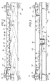
- each rail 12 as shown particularly in Figures 2 and 3 includes an upper head or ball 16, a vertical web 18, and a lower base 20.
- Lower base 20 is mounted on tie plates 22 supported on crossties 24.
- Crossties 24 are mounted on ballast 26 normally comprising crushed rock.
- Pans 10 and 14 are formed of a molded lightweight plastic material, preferably high density polyethylene, having a thickness of preferably about 6.3 mm (1 ⁇ 4 inch) to provide flexibility and resilience. Pans 10 and 14 formed of a lightweight material may be easily stacked vertically for storage or transport prior to installation on a railroad track such as shown in Figure 5 for center pans 10. Also, relatively long length pans such as 4.5 m (15 ft) in length, function in a satisfactory manner. Thus, each row shown in Figure 1 may have a length of 4.5 m (15 ft).
- transverse drain conduit 28 in Figures 3, 4, and 7 is positioned between a pair of crossties 24 beneath the drainage end of pans 10 and 14 to receive the liquid spillage from pans 10 and 14.
- Conduit 28 is of a rectangular cross section having a sloping lower wall 30 and an upper wall 32. Upper wall 32 has an opening 34 for each of pans 10 and 14 to receive the liquid spillage from pans 10 and 14.
- the extending lower sloping end of transverse drain conduit 28 is connected to a catch basin 35 having a longitudinal drain pipe 36 which extends to a collection facility or container (not shown). If desired, catch basin 35 may be omitted with drain pipe 36 connected directly to an end of drain conduit 28.
- Each center pan 10 of a molded plastic construction is resilient and includes a bottom 40, a pair of opposed sides 42, and a flexible resilient upper side flange or lip 44 extending laterally outwardly from each side 42.
- Pan bottom 40 is supported on the upper surface of crossties 24 and has a plurality of molded ribs to provide flow channels for pan 10 and to reinforce pan 10.
- raised rib sections 46 at the upper end 45 of center pan 10 as shown in Figure 2 slope downwardly to the lower opposed end 47 of pan 10 for the drainage of liquid from upper end 45 to lower end 47.
- Main flow channels 48 along bottom 40 are provided adjacent raised rib sections 46. Rib sections 46 have ribs 50 defining shallow flow channels 52 therebetween.
- Rib sections 46 for pan 10 having a length of 4.5 m (15 ft) have a slope of between about 2.5 cm and 5 cm (1 and 2 inches) from upper end 45 to lower end 47.
- Flow channels 48 and 52 are effective in the drainage of solid particles, such as sand, from pan 10.
- Each molded center pan 10 has an integral downwardly extending drain pipe 54 defining an inset annular shoulder 56 to receive in supporting relation a metal grate 58. Drain pipe 54 tapers in a downward direction and is flexible to facilitate fitting within a vertically aligned opening 34 in transverse drain conduit 28.
- an elastomeric sealing sleeve 60 is mounted within opening 34 to receive in sealing relation the lower end of vertical drain pipe 54.
- Sleeve 60 has an annular shoulder 62 that fits about opening 34 and contacts in sealing relation the upper surface of to upper wall 32 of transverse drain conduit 28. The resilience of sleeve 60 and tapered drain pipe 54 provide an effective sealing relation.
- each end 45, 47 has an extending upper end flange 64 which laps an adjacent flange 64 of an adjacent center pan 10.
- Aligned elongate slots 66 are provided in lapping flanges 64 and fasteners 68 having resilient washers fit within aligned slots 66 and are tightened to hold flanges 64 together at ends 45 and 47. Slots 66 permit limited temperature expansion and contraction of adjacent center pans 10 of about 2.5 cm (1 inch).
- Center pans 10 may be easily installed between rails 12 in a minimum of time.
- Transverse drain conduit 28 with sleeves 60 within openings 34 is positioned between a pair of crossties 24 with one crosstie 24 removed to provide adequate space for transverse drain conduit 28.
- a preferred installation method as shown partially in Figure 2 in broken lines comprises the positioning of one resilient side flange 44 beneath the head 16 of an adjacent rail 12 with pan 10 inclined upwardly at about a thirty degree angle to the adjacent rail 12.
- Vertical drain pipe 54 is initially aligned vertically with an associated opening 34 and sealing sleeve 60. Then, the center pan 10 is pushed downwardly with the bottom 40 of pan 10 supported on the upper surface of the crossties 24 and pipe 54 received within resilient sleeve 60 in sealing relation.
- Another method of installing center pan 10 comprises the aligning of drain pipe 54 with sleeve 60 and the pushing or forcing of center pan 10 downwardly onto crossties 24 between rails 12 without inclining center pan 10 so that both side flanges 44 contact the upper surface of adjacent heads 16 and are held thereon. Both resilient side flanges 44 may then be forced beneath heads 16 by a workman with a suitable tool for snapping of side flanges 44 into sealing position beneath heads 16.
- Each side pan 14 has a bottom 72 and raised rib sections 74.
- Main flow channels 76 are provided between raised rib sections 74 which slope downwardly from an upper end 77 shown in Figure 6 to a lower end shown in Figure 7.
- An integral drain tube or pipe 78 extends downwardly from bottom 72 for fitting within an elastomeric sealing sleeve 60 in a manner similar to outer pan 10. Grate 79 is supported on drain pipe 78.
- An inner side 80 has an extending side flange 82 which fits beneath head 16 in sealing relation generally at the juncture of head 16 and vertical web 18. Drain tube or pipe 78 is positioned for urging side flange 82 into sealing relation with head 16 at the lower end of side pan 14 when drain pipe 78 is received within sealing sleeve 60. Also, bottom 72 has elongate slots 81 receiving lag screws 83 and washers which are secured to the crossties 24. An outer channel-shaped side 86 of side pan 14 has an extending lower flange 88 covered with ballast to assist in maintaining side pan 14 in sealing position against head 16 of the adjacent rail 12.
- Each side pan 14 has an upper end flange at each end thereof which is adapted to be positioned and secured in lapping relation to a mating end flange on an adjacent side pan 14 in a manner similar to lapping flanges 64 secured by fasteners 68 as shown in Figure 4 for center pan 10.
- Side pans 14 are arranged in transversely aligned position with center panel 10.
- resilient side flange 82 is pushed manually tightly against the junction of head 16 and vertical web 18 of adjacent rail 12 with drain pipe 78 aligned vertically with seal 60. Then, downwardly extending drain pipe 78 is lowered within elastomeric sealing sleeve 60 in transverse drain conduit 28.
- Ballast is then positioned over extending flange 88 and lag screws 83 with washers are inserted in the crossties through suitable elongate slots 81 in bottom 72 of side pan 14.
- the lag screws 83 are received within a relatively small elongated slot so that limited expansion and contraction of side panel 14 less than about 2.5 cm (1 inch) is provided. In some instances, lag screws 83 may be omitted.
- Spikes 85 are provided for flange 88 and are of a length of about 20 cm (8 inches) for extending within ballast 26 for securement of side pans 14.
Landscapes
- Engineering & Computer Science (AREA)
- Architecture (AREA)
- Civil Engineering (AREA)
- Structural Engineering (AREA)
- Gasket Seals (AREA)
- Railway Tracks (AREA)
- Details Of Rigid Or Semi-Rigid Containers (AREA)
- Lubrication Details And Ventilation Of Internal Combustion Engines (AREA)
Claims (7)
- System zum Sammeln von überlaufender Flüssigkeit an Schienenanlagen, welche ein Paar von Schienen (12) aufweisen, die auf Schwellen (24) abgestützt sinddadurch gekennzeichnet,mit einer Vielzahl von Ablaufwannen (10, 14) aus Kunststoff, die Stirnseite an Stirnseite längs der Seiten der Schienen (12) und zwischen den auf den Schwellen (24) abgestützten Schienen (12) angeordnet sind und angrenzend an die Schienen (12) unter deren Köpfen (16) enden,mit abgeschlossenen querverlaufenden langgestreckten Ablaufleitungen (28), die zwischen Paaren von benachbarten Schwellen (24) unter den Ablaufwannen (10, 14) angeordnet sind und eine obere Fläche vertikal im Abstand von den Ablaufwannen (10, 14) haben,mit Paaren von zugeordneten im Abstand angeordneten Öffnungen in den Ablaufwannen (10, 14) und den querverlaufenden Ablaufleitungen (28) undmit Ablaufrohren (54, 78), die zwischen jedem der Paare von fluchtend ausgerichteten Öffnungen zur Bildung von Strömungskanälen aus den Ablaufwannen (10, 14) zu den abgeschlossenen querverlaufenden Ablaufleitungen (28) angeordnet sind,dass jede Ablaufwanne (10, 14) in einem Stück aus einem homogenen elastischen Material mit geringem Gewicht hergestellt ist,dass jede Ablaufwanne (10, 14) ein Ablaufrohr (54, 78) hat, das in einem Stück mit ihr ausgeformt ist und sich nach unten für ein Einführen in die zugeordnete Öffnung in einer querverlaufenden Ablaufleitung (28) erstreckt,dass um jede der oberen Öffnungen in den querverlaufenden Ablaufleitungen (28) ein elastisches ringförmiges Dichtungselement (60) für die Aufnahme des zugeordnet Ablaufrohrs (54, 78) angeordnet ist, um eine insgesamt fluiddichte Abdichtung daran zu schaffen und um eine begrenzte Bewegung der Ablaufwannen (10 14) bezüglich der querverlaufenden Ablaufleitung (28) zu ermöglichen, unddass jede Ablaufwanne (10, 14) einen sich nach oben erstreckenden geneigten elastischen Seitenflansch (82) oder ein Paar (44) davon für den Eingriff mit der (den) Schiene(n) (12) unter ihrem Kopf (ihren Köpfen) (16) eine Schnappsitzabdichtungsbeziehung hat.
- System nach Anspruch 1, bei welchem das ringförmige Dichtungselement eine elastomere Hülse (60) ist.
- System nach Anspruch 1 oder 2, bei welchem jedes Ablaufrohr (54) eine nach oben weisende Schulter (56) angrenzend an den Boden der Ablaufwanne (10) hat und an der Schulter (52) über dem Ablaufrohr (54) ein Gitterrost (58) angeordnet ist.
- System nach einem der Ansprüche 1 bis 3, bei welchem jede Ablaufwanne (10) eine Vielzahl von sich in Längsrichtung erstreckenden Rippen (50) längs des Bodens (40) der Ablaufwanne (10) hat, die eine Vielzahl von Strömungskanälen (48, 52) zwischen benachbarten Rippen (50) bilden, um flüssige und feste Stoffe zu der Öffnung in den Ablaufwannen (10) zu leiten.
- System nach einem der vorhergehenden Ansprüche, bei welchem die Ablaufwannen (10, 14) aus einem Polyethylen hoher Dichte hergestellt sind.
- System nach einem der vorhergehenden Ansprüche, bei welchem jede Ablaufwanne (10, 14) eine obere Fläche hat, die sich von einem Ende (45, 77) zu ihrem anderen gegenüberliegenden Ende (47) nach unten neigt, und die Öffnungen die Ablaufwanne (10, 14) in dem gegenüberliegenden Ende (47) angeordnet ist.
- System nach einem der vorhergehenden Ansprüche, bei welchem jede der Stirnseite an Stirnseite angeordneten Ablaufwannen (10, 14) einen oberen Stirnflansch (64) hat, der sich in einer überlappenden Beziehung zu einem benachbarten oberen Stirnflansch an einer benachbarten Ablaufwanne (10, 14) erstreckt, und Befestigungseinrichtungen (68) an den überlappenden Stirnflanschen (64) so festgelegt sind, dass eine begrenzte Längsbewegung zwischen benachbarten Ablaufwannen (10, 14) möglich ist, die sich aus Umgebungstemperaturänderungen ergibt.
Applications Claiming Priority (2)
| Application Number | Priority Date | Filing Date | Title |
|---|---|---|---|
| US5974898A | 1998-04-14 | 1998-04-14 | |
| US59748 | 1998-04-14 |
Publications (2)
| Publication Number | Publication Date |
|---|---|
| EP0952253A1 EP0952253A1 (de) | 1999-10-27 |
| EP0952253B1 true EP0952253B1 (de) | 2002-02-13 |
Family
ID=22024971
Family Applications (1)
| Application Number | Title | Priority Date | Filing Date |
|---|---|---|---|
| EP19990106940 Expired - Lifetime EP0952253B1 (de) | 1998-04-14 | 1999-04-08 | Vorrichtung zum Auffangen von Flüssigkeiten im Schienenbereich |
Country Status (3)
| Country | Link |
|---|---|
| EP (1) | EP0952253B1 (de) |
| CA (1) | CA2268736C (de) |
| DE (1) | DE69900873T2 (de) |
Families Citing this family (4)
| Publication number | Priority date | Publication date | Assignee | Title |
|---|---|---|---|---|
| US6290143B1 (en) * | 1996-05-02 | 2001-09-18 | Century Group, L.L.C. | Apparatus and method for collecting liquid spillage at rail facilities |
| DE102006023311B3 (de) * | 2006-05-18 | 2007-11-08 | Thyssenkrupp Gft Gleistechnik Gmbh | Einrichtung zur Abdeckung begehbarer Flächen von Schienenfahrwegen |
| CN103938505B (zh) * | 2014-04-15 | 2015-08-26 | 衡水中铁建工程橡胶有限责任公司 | 轨道交通浮置板用易更换橡胶隔振器及其更换方法 |
| CN116345049B (zh) * | 2023-03-31 | 2025-10-21 | 厦门新能达科技有限公司 | 电化学装置以及用电设备 |
Family Cites Families (5)
| Publication number | Priority date | Publication date | Assignee | Title |
|---|---|---|---|---|
| US4010896A (en) * | 1976-03-25 | 1977-03-08 | Stockton William N | Modular liquid collection system for railroad roadbeds |
| US4300721A (en) | 1980-05-23 | 1981-11-17 | Oneida General Corporation | System for collecting liquid spillage at rail facilities |
| AT405952B (de) * | 1991-10-21 | 2000-01-25 | Lindinger Klaus Johann | Vorrichtung zum schutz des schotterbettes von gleisanlagen gegen umweltschädliche tropfsubstanzen, insbesondere tropföl |
| US5782405A (en) * | 1993-12-27 | 1998-07-21 | Vincent; Jon R. | Railroad track collector pan system |
| DE19548857C2 (de) * | 1995-12-27 | 2000-03-09 | Envitec Umweltsyst Gmbh & Co | Abdeckung für Gleisanlagen |
-
1999
- 1999-04-07 CA CA 2268736 patent/CA2268736C/en not_active Expired - Lifetime
- 1999-04-08 EP EP19990106940 patent/EP0952253B1/de not_active Expired - Lifetime
- 1999-04-08 DE DE1999600873 patent/DE69900873T2/de not_active Expired - Fee Related
Also Published As
| Publication number | Publication date |
|---|---|
| CA2268736A1 (en) | 1999-10-14 |
| DE69900873D1 (de) | 2002-03-21 |
| DE69900873T2 (de) | 2002-11-07 |
| EP0952253A1 (de) | 1999-10-27 |
| CA2268736C (en) | 2002-12-10 |
Similar Documents
| Publication | Publication Date | Title |
|---|---|---|
| US6415987B2 (en) | Method for collecting liquid spillage at rail facilities | |
| US4300721A (en) | System for collecting liquid spillage at rail facilities | |
| US7007343B2 (en) | In-floor, adjustable, multiple-configuration track assembly for sliding panels with built-in weep system | |
| CA1329959C (en) | Leaching system conduit | |
| US9267243B2 (en) | Surface and sub-surface drain system | |
| CA2333559C (en) | Railway or tramway rail and rail fastening system | |
| US5015122A (en) | System permitting channeling of drainage fluid | |
| US20050025572A1 (en) | Modular trench drain | |
| US4010896A (en) | Modular liquid collection system for railroad roadbeds | |
| US7866911B2 (en) | Slotted drain | |
| US4117977A (en) | Highway-railway crossing | |
| EP0952253B1 (de) | Vorrichtung zum Auffangen von Flüssigkeiten im Schienenbereich | |
| CA2265104A1 (en) | Drainage system for tunnels | |
| EP1995380A2 (de) | Vorrichtung zum Sammeln von Flüssigkeiten längs von Bahnlinien | |
| DE3818952A1 (de) | Auffangvorrichtung in gleisanlagen, zum schutz von boden und grundwasser vor schadstoffeintrag | |
| US5782405A (en) | Railroad track collector pan system | |
| HU221915B1 (hu) | Vasúti vágány | |
| EP0819197B1 (de) | Entwässerungsanlage für strassen | |
| EP2243355A1 (de) | Modularer belüfteter Fußbodenbelag, insbesondere für Ställe und/oder Schweinefarmen | |
| US4421272A (en) | Splicing and grade crossing construction | |
| CA2256772C (en) | Railroad track collector pan system | |
| CA1081192A (en) | Liquid collection system for railroad roadbeds | |
| JPH01146001A (ja) | 排水溝 | |
| JP2515688Y2 (ja) | 道路の継ぎ目構造 | |
| JPS636300Y2 (de) |
Legal Events
| Date | Code | Title | Description |
|---|---|---|---|
| PUAI | Public reference made under article 153(3) epc to a published international application that has entered the european phase |
Free format text: ORIGINAL CODE: 0009012 |
|
| AK | Designated contracting states |
Kind code of ref document: A1 Designated state(s): BE DE FR GB NL |
|
| AX | Request for extension of the european patent |
Free format text: AL;LT;LV;MK;RO;SI |
|
| 17P | Request for examination filed |
Effective date: 20000327 |
|
| AKX | Designation fees paid |
Free format text: BE DE FR GB NL |
|
| RAP1 | Party data changed (applicant data changed or rights of an application transferred) |
Owner name: CENTURY GROUP, L.L.C. |
|
| GRAG | Despatch of communication of intention to grant |
Free format text: ORIGINAL CODE: EPIDOS AGRA |
|
| 17Q | First examination report despatched |
Effective date: 20010426 |
|
| GRAG | Despatch of communication of intention to grant |
Free format text: ORIGINAL CODE: EPIDOS AGRA |
|
| GRAH | Despatch of communication of intention to grant a patent |
Free format text: ORIGINAL CODE: EPIDOS IGRA |
|
| GRAH | Despatch of communication of intention to grant a patent |
Free format text: ORIGINAL CODE: EPIDOS IGRA |
|
| GRAA | (expected) grant |
Free format text: ORIGINAL CODE: 0009210 |
|
| REG | Reference to a national code |
Ref country code: GB Ref legal event code: IF02 |
|
| AK | Designated contracting states |
Kind code of ref document: B1 Designated state(s): BE DE FR GB NL |
|
| PG25 | Lapsed in a contracting state [announced via postgrant information from national office to epo] |
Ref country code: NL Free format text: LAPSE BECAUSE OF FAILURE TO SUBMIT A TRANSLATION OF THE DESCRIPTION OR TO PAY THE FEE WITHIN THE PRESCRIBED TIME-LIMIT Effective date: 20020213 |
|
| REF | Corresponds to: |
Ref document number: 69900873 Country of ref document: DE Date of ref document: 20020321 |
|
| NLV1 | Nl: lapsed or annulled due to failure to fulfill the requirements of art. 29p and 29m of the patents act | ||
| ET | Fr: translation filed | ||
| PLBE | No opposition filed within time limit |
Free format text: ORIGINAL CODE: 0009261 |
|
| STAA | Information on the status of an ep patent application or granted ep patent |
Free format text: STATUS: NO OPPOSITION FILED WITHIN TIME LIMIT |
|
| 26N | No opposition filed |
Effective date: 20021114 |
|
| PGFP | Annual fee paid to national office [announced via postgrant information from national office to epo] |
Ref country code: FR Payment date: 20040421 Year of fee payment: 6 |
|
| PGFP | Annual fee paid to national office [announced via postgrant information from national office to epo] |
Ref country code: BE Payment date: 20040427 Year of fee payment: 6 |
|
| PGFP | Annual fee paid to national office [announced via postgrant information from national office to epo] |
Ref country code: GB Payment date: 20040428 Year of fee payment: 6 |
|
| PGFP | Annual fee paid to national office [announced via postgrant information from national office to epo] |
Ref country code: DE Payment date: 20040629 Year of fee payment: 6 |
|
| PG25 | Lapsed in a contracting state [announced via postgrant information from national office to epo] |
Ref country code: GB Free format text: LAPSE BECAUSE OF NON-PAYMENT OF DUE FEES Effective date: 20050408 |
|
| PG25 | Lapsed in a contracting state [announced via postgrant information from national office to epo] |
Ref country code: BE Free format text: LAPSE BECAUSE OF NON-PAYMENT OF DUE FEES Effective date: 20050430 |
|
| BERE | Be: lapsed |
Owner name: *CENTURY GROUP LLC Effective date: 20050430 |
|
| PG25 | Lapsed in a contracting state [announced via postgrant information from national office to epo] |
Ref country code: DE Free format text: LAPSE BECAUSE OF NON-PAYMENT OF DUE FEES Effective date: 20051101 |
|
| GBPC | Gb: european patent ceased through non-payment of renewal fee |
Effective date: 20050408 |
|
| PG25 | Lapsed in a contracting state [announced via postgrant information from national office to epo] |
Ref country code: FR Free format text: LAPSE BECAUSE OF NON-PAYMENT OF DUE FEES Effective date: 20051230 |
|
| REG | Reference to a national code |
Ref country code: FR Ref legal event code: ST Effective date: 20051230 |
|
| BERE | Be: lapsed |
Owner name: *CENTURY GROUP LLC Effective date: 20050430 |