EP0952277A1 - Teleskopartige Arbeitsplatte - Google Patents
Teleskopartige Arbeitsplatte Download PDFInfo
- Publication number
- EP0952277A1 EP0952277A1 EP99400996A EP99400996A EP0952277A1 EP 0952277 A1 EP0952277 A1 EP 0952277A1 EP 99400996 A EP99400996 A EP 99400996A EP 99400996 A EP99400996 A EP 99400996A EP 0952277 A1 EP0952277 A1 EP 0952277A1
- Authority
- EP
- European Patent Office
- Prior art keywords
- platform
- sections
- suitcase
- parts
- platform according
- Prior art date
- Legal status (The legal status is an assumption and is not a legal conclusion. Google has not performed a legal analysis and makes no representation as to the accuracy of the status listed.)
- Withdrawn
Links
- 230000002787 reinforcement Effects 0.000 claims abstract description 4
- 238000000926 separation method Methods 0.000 claims description 5
- 230000006835 compression Effects 0.000 description 3
- 238000007906 compression Methods 0.000 description 3
- 238000004519 manufacturing process Methods 0.000 description 2
- 229910001220 stainless steel Inorganic materials 0.000 description 2
- 239000010935 stainless steel Substances 0.000 description 2
- 229910001369 Brass Inorganic materials 0.000 description 1
- 229910000737 Duralumin Inorganic materials 0.000 description 1
- 239000010951 brass Substances 0.000 description 1
- 230000000295 complement effect Effects 0.000 description 1
- 238000003780 insertion Methods 0.000 description 1
- 230000037431 insertion Effects 0.000 description 1
- 239000000463 material Substances 0.000 description 1
- 238000012986 modification Methods 0.000 description 1
- 230000004048 modification Effects 0.000 description 1
- 238000003466 welding Methods 0.000 description 1
Images




Classifications
-
- E—FIXED CONSTRUCTIONS
- E04—BUILDING
- E04G—SCAFFOLDING; FORMS; SHUTTERING; BUILDING IMPLEMENTS OR AIDS, OR THEIR USE; HANDLING BUILDING MATERIALS ON THE SITE; REPAIRING, BREAKING-UP OR OTHER WORK ON EXISTING BUILDINGS
- E04G1/00—Scaffolds primarily resting on the ground
- E04G1/34—Scaffold constructions able to be folded in prismatic or flat parts or able to be turned down
Definitions
- the present invention relates to a platform comprising a work platform and lateral parts for access to the work platform.
- platforms of this type comprising a square or rectangular work platform and lateral parts respectively provided with two uprights, at least one of which is used to access the work platform. by means of at least two steps connected between the uprights thereof.
- Some platforms have side parts which can fold over one another so as to have a reduced bulk and be easily transportable when they are not in use.
- the uprights of one of the lateral parts of the platform are generally articulated with respect to the uprights of the other lateral part of the platform at a level higher than that of the work platform.
- the latter has an edge which is pivotally mounted between the uprights of one of the side parts of the platform so that it can be tilted upwards in a vertical position, when the side parts of the platform are folded over one another. the platform.
- the present invention therefore essentially aims to remedy the drawbacks mentioned above of platforms of known type.
- the platform according to the invention is characterized in that the lateral parts for access to the work platform respectively comprise telescopic uprights and are respectively provided with pivoting means, so as to be folded down one after the other.
- the other inside a briefcase or suitcase, the bottom and the side walls of the briefcase or suitcase respectively constituting the work platform and the lateral reinforcements of the work platform of the platform.
- One of the advantages of the platform according to the present invention lies in the fact that the uprights are adjustable in height automatically by a locking / unlocking means integrated in each of the lateral parts of the platform, in the upper steps associated with each of them.
- the work plate 1 is constituted by a plate whose external surface is non-slip which preferably, but not necessarily, has the shape of a rectangle whose four sides are respectively provided with vertical edges 4, 5, 6 and 7 which protrude under the plate of the plate 1 and which form the reinforcements of the latter.
- edges preferably consist of L-shaped sections of identical section and thickness which have their corresponding small branches (not shown) fixed, for example welded, respectively under the edges of the plate, and extended downwards by their large corresponding branches 4A, 5A, 6A and 7A.
- the tray 1 and the large branches corresponding 4A, 5A, 6A and 7A of the sections 4, 5, 6 and 7 respectively form, in an advantageous manner, the bottom wall and the four side walls of a case or suitcase 8 equipped with a cover 9 and d a handle 10, the latter being fixed, for example screwed, preferably on the branch 5A of the profile 5.
- the cover 9 is constituted by a plate of the same type as that forming the work plate 1 which has been described above, whose outer surface is for example non-slip, and which breaks down into a central part 9A and two lateral parts 9B and 9C.
- the central part 9A of the cover 9 is constituted by a substantially rectangular plate, the four corners of which are respectively cut along a first line perpendicular to the short sides of the plate 9A and along a second line forming with the first line a angle preferably equal to 120 °.
- One of the short sides of the plate 9A is articulated, for example by means of a hinge 11, on the free edge of one of the large branches of the sections 5 and 7, for example the branch 7A (not shown).
- the other short side of the plate 9A is provided with any fastening device, preferably a latch 12 fixed, for example screwed, on the plate 9A, which is intended to come to engage in a curved element fixed on the large branch 5A of the profile 5 so as to close the cover 9.
- the two lateral parts 9B and 9C of the cover 9 are, in turn, constituted by two plates in all identical points, of substantially rectangular shape, the structure and l 'thickness are the same as those of the plate 9A.
- the other long sides of the plates 9B and 9C have a cut whose shape is complementary to that of the cutouts arranged respectively on the long sides of the plate 9A. To close the cover 9, it suffices first to fold the plates 9B and 9C, then the plate 9A, the large edges of which respectively cover the large cut edges of the plates 9B and 9C, and finally to lock the plate 9A by means of the sleepsuit 12.
- the lateral parts 2 and 3 each comprise two uprights 2A, 2B and 3A, 3B which are constituted by profiles of square section between which are fixed respectively, for example welded, three steps E1, E2, E3 and E'1, E'2, E'3 also formed by square section profiles.
- the lateral parts 2 and 3 each comprise several sections arranged one after the other, for example respectively three sections T1, T2, T3 and T'1, T'2 and T'3.
- each of the sections T1, T2 and T3 have a section adapted so that the amounts of the lower section T3 (respectively T'3) are capable of s' fit into the uprights of the intermediate section T2 (respectively T'2) and the uprights of the section T2 (respectively T'2) are likely to fit into the uprights of the upper section T1 (respectively T'1).
- the interlocking of the uprights is enabled by the actuation of locking / unlocking means V1, V2 (respectively V'1, V'2) in all identical points, which are contained respectively in the steps E1, E2 (respectively E'1, E'2).
- V1 locking / unlocking means
- FIG. 3 It consists of two rods 15 and 15 ′, for example of circular section, arranged respectively in the left and right parts of the step E1, in the axis of the latter.
- the left part of the rod 15 and the right part of the rod 15 ' are embedded respectively in profiles 16 and 16' of square section which are capable of sliding in both directions along the rung E1, respectively in profiles 17 and 17 'having a square section adapted so that there is sufficient clearance between the section 16 (respectively 16') and the section 17 (respectively 17 '), this in order to allow sliding.
- the rods 15 and 15 ' can slide in both directions because they are connected together by one of their ends, in a profile 18 of the same type as the profiles 17 or 17' and arranged in the central part of the step E1, respectively by means of two compression springs 19, 19 ', preferably made of stainless steel.
- the sides of the part 20 adjacent to these two sides are open and are respectively opposite two holes 21 and 22 formed in the rung E1, so as to be able to introduce into the latter, and consequently into the profile 18 and the part 20, a fixing element 23, such as for example a pin.
- the corresponding free ends of the rods 15 and 15' protrude from the free ends of the rung E1 so as to be introduced respectively in first and second holes (not shown) which are formed respectively on the corresponding inner sides of the uprights 2A and 2B of the section T1.
- V1, V2 (respectively V'1, V'2)
- the sections T1 and T2 (respectively T'1 and T'2), as well as the sections T2 and T3 (respectively T'2 and T'3) are rigidly and securely locked with respect to one another when the platform 1 is in the working position, giving the latter a certain level of safety in use.
- sections T1, T2 and T3 (respectively T'1, T'2 and T'3), i.e. compress the springs 19 and 19 ', just push with your fingers, in the direction of the profile central 18, two pins 24 and 24 'which are fixed, for example welded, respectively under the lower sides of the sections 16 and 16'.
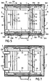
- the sections T3, T2 and T1 (respectively T'3, T'2 and T'1) can then slide respectively into one another, as shown in FIG. 5. It is then made so that the length of the side parts 2 and 3 in the retracted state is less than the length of the plate of the work tray 1 forming the bottom of the case or suitcase 8.
- the use of the locking / unlocking means V1, V2 (respectively V'1, V'2) which have been described above is simple, these having in addition the main advantage of allowing set one of the side parts 2 and 3 to a different height from the other by unlocking the section T3 (or T'3), or even the sections T3 and T2 (or T'3 and T'2), and sliding them in the section T1 (or T'1).
- This possibility can be very practical in the case in particular of staircase work.
- the different adjustment heights of the side parts 2 and 3 are 300, 500 or 700mm.
- the existence of the central section 18 and the pin 23 advantageously allow quick and easy access to the locking / unlocking means V1, V2, V'1 and V'2 when a failure occurs. in their mechanism.
- the platform according to the invention in the working position, rests on feet 25A, 25B integral with the lowest section T3 of the side part 2, and on feet 25'A and 25'B integral with the lowest section T'3 of the lateral part 3.
- the feet 25A and 25B are made up respectively by profiles having a square section. These sections each include a first section TR which is parallel to the uprights and a second section TR 'which extends the section TR in a direction perpendicular thereto. The free end of each section TR is intended to be in contact with the ground and, for this, is provided with a pad P, for example made of rubber.
- each section TR ' is, for its part, introduced with little play in the free end of the profile constituting the rung E3 (E'3 respectively) which is associated with it.
- the sections constituting the feet 25A, 25B, 25'A and 25'B respectively have a section which is slightly smaller than the section of the sections constituting the steps E3 and E'3 respectively.
- the feet 25A and 25B are respectively spread outwards from the uprights 2A and 2B (respectively 3A and 3B) of the section T3 (respectively T'3 ), so that the platform according to the invention has sufficient stability in use. More particularly with reference to FIG.
- an elastic means V3 (respectively V'3) is contained in the step E3 (respectively E'3) to be able to bring the feet 25A and 25B (respectively 25'A and 25'B) against the uprights 2A and 2B (respectively 3A and 3B) so that they do not take up too much space in the case or suitcase 8, as illustrated in FIG. 5.
- the elastic means V3 consists of a compression spring 26, for example made of stainless steel, the free ends of which are introduced respectively into the corresponding free ends of the sections TR '.
- Two longitudinal windows F and F 'of small thickness are arranged in the lower side of the rung E3 (E'3 respectively).
- These windows are intended to receive respectively two pins, screws or the like T and T 'which are capable of sliding respectively therein.
- the pins T and T ' are respectively in abutment against the extreme left and right edges of the windows F and F'.
- the pins T and T ' are respectively in abutment against the extreme right and left edges of the windows F and F'.
- a tab can be provided connecting the pins T and T 'to each other.
- This tab would have a hole at one of its ends, in which would be engaged one of the studs T and T ', for example the stud T.
- a notch would be formed at the other end of the tab and would be intended to come engaged with the stud T 'so as to maintain the feet 25A, 25B (respectively 25'A, 25'B) in the contracted state.
- the feet 25A, 25B By a simple rotation of the tab relative to the stud T, releasing the stud T 'from the notch, the feet 25A, 25B (respectively 25'A, 25'B) would then move away automatically.
- two identical tubes 27 and 28, for example made of brass, are arranged perpendicular to the large side walls 5 and 7 of the case or suitcase 8, along its small side walls 4 and 6.
- the tube 27 (respectively 28) passes through the upper end of the uprights 2A and 2B (respectively 3A and 3B) by means of holes formed therein.
- the side parts 2 and 3 have the possibility of pivoting one after the other respectively with respect to the tubes 27 and 28 in the direction of their deployment or in the opposite direction.
- the side parts 2 and 3 are folded down in the case or suitcase 8, it is made so that the amounts 2A and 2B of the side part 2 are positioned respectively on the amounts 3A and 3B of the side part 3 at a level which is not higher than that of the free edges of the branches 4A, 5A, 6A and 7A of the sections 4, 5, 6 and 7 respectively forming the lateral parts of the case or suitcase 8.
- the tubes 27 and 28 are fixed by their corresponding free ends, for example by means of bolts, between the vertical wings 29A and 30A associated respectively with two L-shaped sections 29 and 30, which are fixed, for example welded, by their corresponding horizontal wing, to the surface bottom of the plate forming the bottom 1 of the case or suitcase 8.
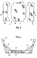
- FIG. 6 One of the vertical wings of these sections 29 and 30, for example the wing 29A, is shown in enlarged view in FIG. 6.
- this comprises, like the wing 30A of the section 30, two slots 31 and 32 parallel, offset from each other in the longitudinal direction and having a determined length.
- Two long and flat parts 33 and 34 of suitable length slide respectively by one of their free ends in the slots 31 and 32, their other corresponding free ends being fixed respectively, for example bolted, on the sides of the uprights 2A and 3A which face the branch 5A of the profile 5 forming one of the large side walls of the case or suitcase 8 (see FIG. 5).
- these parts 33 and 34 have the advantage of playing the role of safety compass by limiting the deployment of the lateral parts 2 and 3 of the platform when the latter passes into the position of job.
- the length and position of the slots 31 and 32, as well as the length of the compass 33 and 34 have been adapted so that the uprights 2A, 2B and 3A, 3B of the platform are deployed with a maximum angle of 105 ° relative to the plate forming the bottom 1 of the case or suitcase 8.
- side parts 9B and 9C of the cover 9 are not, like the part 9A, in the closed position, but hang on each side of the plate forming the work plate 1, their cutout having been adapted so as not to hinder the '' access to upper levels E1 and E'1.
- a removable guardrail 35 as shown in Figures 1 and 5, which is constituted by a U-shaped profile having dimensions suitable for being housed in the case or suitcase 8, in a space between the profiles 29, 30, the pivot tube 27 or 28 and respectively the side walls 7, 5 and 4 or 6 of the case or suitcase 8.
- Two profiles 36A and 36B of rectangular section and open at their opposite ends are fixed vertically, preferably welded, by one of their open ends in the bottom of the case or suitcase 8, respectively near the free ends of the pivot tube 27 or 28, for example of the tube 28.
- the other corresponding open ends of the sections 36A and 36B communicate respectively with openings (not shown) formed in the work plate 1, so as to receive respectively the free ends of the railing 35 when the platform is in the working position.
- the invention therefore provides a platform that is very easy to transport because it can be folded up in the case or suitcase 8, which has a reduced bulk since its length, width and depth do not not exceed 500mm, 400mm and 600mm respectively.
- the platform / case assembly will be made of a light material such as, for example, duralumin.
- This platform having the added advantage of being easily and quickly installed, will be particularly intended for people who often move from one place to another, such as for example artisans, photographers in report. It will also suit DIY enthusiasts or spectators of public events who are embarrassed by other spectators who stand in front of them in the crowd.
- the user releases the latch 12 and deploys the central part 9A as well as the lateral parts 9B and 9C of the cover 9, which pivot respectively towards the outside of the briefcase or suitcase 8 by relative to the hinges 11, 13 and 14. Then, it releases the lateral part 2 of the platform by rotating it relative to the tube 28 and leaves the sections T2 and T3 by actuating the pins 24 and 24 'of the locking means / unlocking V1 and V2.
- notches 38A and 38B are fitted in the branch 4A of the profile 4 forming one of the small side walls of the case or suitcase 8. These notches have a section slightly greater than the section of the uprights 2A and 2B of the section T1 and are formed so as to be in correspondence with said uprights, this in order to be able to extend the lateral part 2, when the latter is flat in the bottom of the case or suitcase 8, outside of the latter.
- the user folds the parts 9B, 9C and 9A of the cover 9 onto the suitcase or case 8 and locks the central part 9A of the cover 9 by means of the latch 12. Finally, the latter has only to introduce the ends of the railing 35 respectively into the profiles 36A and 36B.
- the user obtains, as one can see on figure 8, a devil whose file, the flap and the handles consist, in a clever way, respectively by the briefcase or suitcase 8, the guardrail 35 and the lowest section T3 of the lateral part 2 of access to the work platform 1.
- the platform comprises a horizontal work plate 1 extended vertically, on the one hand by flanges 5A and 7A perpendicular to the access parts 2 and 3, and on the other hand, by vertical edges 4A and 6A parallel to the access parts 2 and 3. Furthermore, these edges 4A and 6A are respectively extended horizontally, towards the inside of the case, by edges 39B and 39C, as best seen in Figure 10.
- the front face of the case 8 is broken down into a movable central cover 39 and two fixed lateral parts 39B and 39C which have just been described.
- the cover 39 consists of a rectangular plate articulated on the edge 7A by means of a hinge 11.
- the two lateral parts 39B and 39C they each have two square cutouts of sufficient size to allow the insertion of the lateral parts 2A, 2B, 3A and 3B of the platform.
- this first set excluding the cover 39 can be advantageously by means of a sheet in which the necessary cuts are made, then which is introduced into a press brake to give it the configuration described above, the junctions between the different flanges 4A, 5A, 6A and 7A then being carried out by welding.
- this embodiment does not include a compass system 33 and 34, nor grooves in the side 29A, which simplifies the manufacture and the use of the platform.
- the user wanting to put it in the working position unlocks the plate 39, opens it, unfolds the lateral access parts 2A, 2B, 3A and 3B which are housed in the cutouts of the parts 39B and 39C, then he closes the plate 39 and locks it again.
- the degree of spacing of each side part 2A, 2B, 3A and 3B is then respectively limited by the bottom 40, 41, 42 and 43 of the square cutouts of the parts 39B and 39C.
- the plate 39 once locked, it prevents these lateral parts from folding back.
- This embodiment also includes differences in the removable railing which is no longer articulated at the bottom of the case, but directly on the uprights 3A and 3B of the access side part 3, as can be seen on Figure 9.
- the railing consists of a profile 45 which can slide inside another hollow profile 44 having at each of its two lower ends two elongated oval slots located opposite each other.
- Each upright 3A and 3B comprise a welded stirrup in the vicinity of the plate 1 and which receives each of the lower ends of the section 44. These stirrups are each provided with a horizontal axis which passes through the lights of the section 44.
- the platform may include a system for fixing a telescopic mast, more particularly intended for photographers for their cameras, or for artisans to hang their equipment there.
- This system can, for example, be advantageously supported by the railing which has just been described.
- the E'1 rung can equip the E'1 rung with a hollow cylinder provided with a bottom, serving as a receptacle at the lower end of the mast, and fix a cylindrical collar provided with a clamping screw on the bar.
- horizontal profile 44 perpendicular to the cylinder.
- a second collar fitted with a clamping screw can be attached to the section 45 and the said mast made using three or four sections of tubes which fit into each other.
- the platform When the platform is in the working position, it is enough to deploy the sections of the telescopic mast, then to insert the largest section in the clamp of the profile 45, then in the clamp of the profile 44 and finally in the cylinder of step E'1.
- the assembly is then fixed by means of the screws provided for this purpose.
- the height of the different sections being preferably chosen so that once fitted into each other, the height total does not exceed approximately 75% of the width of the case.
- the cover 9 instead of having a central part 9A made in one piece which is relatively bulky when deployed, could have a central part 9A in two sub-parts articulated respectively with respect to the large branches 5A and 7A sections 5 and 7 forming the large side walls of the case or suitcase 8.
- the cover 9 would close in the center for example by a targette.
- the bolt of the targette would be fixed, for example screwed, on one of the sub-parts of the central part 9A of the cover.
- the keeper of the bolt, for its part would be fixed, for example screwed, on a support arch housed vertically in the case or suitcase 8.
- An opening would of course be arranged in the other sub-part of the central part 9A of the cover to allow the passage of the striker.
- an additional opening could be formed in the center of the work platform of the platform forming the bottom 1 of the case or suitcase 8. This opening would in fact serve as a handle for easily moving the platform when it is in the working position as illustrated in FIG. 1.
- the edge of said opening would be bent towards inside the briefcase or suitcase 8 to prevent the user from injuring his hand when moving the platform.
Landscapes
- Engineering & Computer Science (AREA)
- Architecture (AREA)
- Mechanical Engineering (AREA)
- Civil Engineering (AREA)
- Structural Engineering (AREA)
- Purses, Travelling Bags, Baskets, Or Suitcases (AREA)
Applications Claiming Priority (2)
| Application Number | Priority Date | Filing Date | Title |
|---|---|---|---|
| FR9805075A FR2777929B1 (fr) | 1998-04-23 | 1998-04-23 | Plate-forme telescopique |
| FR9805075 | 1998-04-23 |
Publications (1)
| Publication Number | Publication Date |
|---|---|
| EP0952277A1 true EP0952277A1 (de) | 1999-10-27 |
Family
ID=9525575
Family Applications (1)
| Application Number | Title | Priority Date | Filing Date |
|---|---|---|---|
| EP99400996A Withdrawn EP0952277A1 (de) | 1998-04-23 | 1999-04-23 | Teleskopartige Arbeitsplatte |
Country Status (2)
| Country | Link |
|---|---|
| EP (1) | EP0952277A1 (de) |
| FR (1) | FR2777929B1 (de) |
Cited By (2)
| Publication number | Priority date | Publication date | Assignee | Title |
|---|---|---|---|---|
| EP1788167A1 (de) | 2005-11-18 | 2007-05-23 | Telesteps AB | Zusammenklappbares Gerüst |
| WO2007132148A3 (en) * | 2006-05-04 | 2008-01-10 | Access Products Ltd | Scaffolding |
Families Citing this family (2)
| Publication number | Priority date | Publication date | Assignee | Title |
|---|---|---|---|---|
| CN107265369A (zh) * | 2017-07-18 | 2017-10-20 | 苏州飞华铝制工业有限公司 | 一种梯柱和脚皿均可伸缩的工作台 |
| FR3096381B1 (fr) | 2019-05-24 | 2022-03-25 | Cdh Group | Systeme d’assemblage de plateformes sans outils |
Citations (8)
| Publication number | Priority date | Publication date | Assignee | Title |
|---|---|---|---|---|
| US2782075A (en) * | 1955-04-04 | 1957-02-19 | Fagan Roscoe | Collapsible bench |
| US3722621A (en) * | 1971-06-01 | 1973-03-27 | M Jones | Ladder bench |
| FR2311154A1 (fr) * | 1975-05-13 | 1976-12-10 | Frassetto Jean Pierre | Echafaudage pliant |
| US4026221A (en) * | 1975-10-29 | 1977-05-31 | Sico Incorporated | Multi-leg mobile folding stage |
| US4298093A (en) * | 1978-11-16 | 1981-11-03 | Little Giant Industries, Inc. | Sawhorse |
| US5029671A (en) * | 1990-08-20 | 1991-07-09 | Larson Robert L | Mechanic's walk |
| US5368126A (en) * | 1993-03-29 | 1994-11-29 | Woodward; Wilbur W. | Adjustable work platform |
| EP0814219A1 (de) * | 1996-06-20 | 1997-12-29 | SGB Comabi | Leichte transportabele Arbeitsplattform |
-
1998
- 1998-04-23 FR FR9805075A patent/FR2777929B1/fr not_active Expired - Fee Related
-
1999
- 1999-04-23 EP EP99400996A patent/EP0952277A1/de not_active Withdrawn
Patent Citations (8)
| Publication number | Priority date | Publication date | Assignee | Title |
|---|---|---|---|---|
| US2782075A (en) * | 1955-04-04 | 1957-02-19 | Fagan Roscoe | Collapsible bench |
| US3722621A (en) * | 1971-06-01 | 1973-03-27 | M Jones | Ladder bench |
| FR2311154A1 (fr) * | 1975-05-13 | 1976-12-10 | Frassetto Jean Pierre | Echafaudage pliant |
| US4026221A (en) * | 1975-10-29 | 1977-05-31 | Sico Incorporated | Multi-leg mobile folding stage |
| US4298093A (en) * | 1978-11-16 | 1981-11-03 | Little Giant Industries, Inc. | Sawhorse |
| US5029671A (en) * | 1990-08-20 | 1991-07-09 | Larson Robert L | Mechanic's walk |
| US5368126A (en) * | 1993-03-29 | 1994-11-29 | Woodward; Wilbur W. | Adjustable work platform |
| EP0814219A1 (de) * | 1996-06-20 | 1997-12-29 | SGB Comabi | Leichte transportabele Arbeitsplattform |
Cited By (5)
| Publication number | Priority date | Publication date | Assignee | Title |
|---|---|---|---|---|
| EP1788167A1 (de) | 2005-11-18 | 2007-05-23 | Telesteps AB | Zusammenklappbares Gerüst |
| WO2007057280A1 (en) * | 2005-11-18 | 2007-05-24 | Telesteps Ab | Collapsible platform |
| JP2009516104A (ja) * | 2005-11-18 | 2009-04-16 | テレステップス アクティエボラーグ | 折り畳み可能作業台 |
| RU2425938C2 (ru) * | 2005-11-18 | 2011-08-10 | Телестепс Аб | Складная платформа |
| WO2007132148A3 (en) * | 2006-05-04 | 2008-01-10 | Access Products Ltd | Scaffolding |
Also Published As
| Publication number | Publication date |
|---|---|
| FR2777929A1 (fr) | 1999-10-29 |
| FR2777929B1 (fr) | 2000-06-02 |
Similar Documents
| Publication | Publication Date | Title |
|---|---|---|
| FR2510060A1 (fr) | Poussette de bebe | |
| FR2524787A1 (fr) | Lit pour bebe | |
| EP0597848A1 (de) | Zusammenklappbarer und tragbarer liegestuhl | |
| WO2015197998A1 (fr) | Structure de jeu pour la pratique du basketball | |
| EP2195497B1 (de) | Zusammenklappbarer zaun | |
| FR2929304A1 (fr) | Dispositif d'echafaudage repliable et a hauteur de travail modulable | |
| FR2829082A1 (fr) | Dispositif formant porte-velos pour le transport d'au moins une bicyclette transversalement a l'arriere d'un vehicule automobile | |
| FR2820382A1 (fr) | Dispositif formant porte-velos pour le transport d'au moins une bicyclette transversalement a l'arriere d'un vehicule automobile | |
| FR2777929A1 (fr) | Plate-forme telescopique | |
| EP3015595B1 (de) | Bügelbrett mit hoher sicherheit | |
| FR2750152A1 (fr) | Plateforme de travail individuelle roulante legere | |
| FR2632262A3 (fr) | Chariot a bagages pliant | |
| FR2890677A1 (fr) | Plateforme individuelle de travail | |
| EP1097656B1 (de) | Tischart welche mit mindestens einem faltbaren Fuss oder Untergestell versehen ist | |
| EP0282385B1 (de) | Vorrichtung zur Verankerung an Dachsparren bei Dacharbeiten | |
| WO2021148732A1 (fr) | Abri repliable de type gazebo | |
| WO2015197997A1 (fr) | Structure de jeu comprenant une base disposée en appui sur le sol | |
| FR2862679A1 (fr) | Escalier et echelle pliables a encombrement reduit | |
| EP3093249B1 (de) | Zusammenklappbarer behälter | |
| FR2828522A1 (fr) | Echelle, en particulier pour caravanes autotractees et vehicules automobiles analogues | |
| FR2732567A1 (fr) | Dispositif de verrouillage de meubles basculants | |
| EP1057595A1 (de) | Zusammenklappbarer Arbeitsbock | |
| FR2729164A1 (fr) | Panneau de signalisation deployable | |
| EP4406705A1 (de) | Rolle und/oder kugel | |
| FR3140901A1 (fr) | Dispositif de gestion d’usage d’une échelle |
Legal Events
| Date | Code | Title | Description |
|---|---|---|---|
| PUAI | Public reference made under article 153(3) epc to a published international application that has entered the european phase |
Free format text: ORIGINAL CODE: 0009012 |
|
| AK | Designated contracting states |
Kind code of ref document: A1 Designated state(s): AT BE CH CY DE DK ES FI FR GB GR IE IT LI LU MC NL PT SE |
|
| AX | Request for extension of the european patent |
Free format text: AL;LT;LV;MK;RO;SI |
|
| AKX | Designation fees paid | ||
| REG | Reference to a national code |
Ref country code: DE Ref legal event code: 8566 |
|
| STAA | Information on the status of an ep patent application or granted ep patent |
Free format text: STATUS: THE APPLICATION IS DEEMED TO BE WITHDRAWN |
|
| 18D | Application deemed to be withdrawn |
Effective date: 20000428 |