EP0952344A2 - Soupape de contrÔle de débit d'un compresseur à capacité variable pour réfrigérant - Google Patents
Soupape de contrÔle de débit d'un compresseur à capacité variable pour réfrigérant Download PDFInfo
- Publication number
- EP0952344A2 EP0952344A2 EP99106298A EP99106298A EP0952344A2 EP 0952344 A2 EP0952344 A2 EP 0952344A2 EP 99106298 A EP99106298 A EP 99106298A EP 99106298 A EP99106298 A EP 99106298A EP 0952344 A2 EP0952344 A2 EP 0952344A2
- Authority
- EP
- European Patent Office
- Prior art keywords
- pressure
- refrigerant
- flow control
- control valve
- discharge
- Prior art date
- Legal status (The legal status is an assumption and is not a legal conclusion. Google has not performed a legal analysis and makes no representation as to the accuracy of the status listed.)
- Granted
Links
Images


Classifications
-
- F—MECHANICAL ENGINEERING; LIGHTING; HEATING; WEAPONS; BLASTING
- F04—POSITIVE - DISPLACEMENT MACHINES FOR LIQUIDS; PUMPS FOR LIQUIDS OR ELASTIC FLUIDS
- F04B—POSITIVE-DISPLACEMENT MACHINES FOR LIQUIDS; PUMPS
- F04B27/00—Multi-cylinder pumps specially adapted for elastic fluids and characterised by number or arrangement of cylinders
- F04B27/08—Multi-cylinder pumps specially adapted for elastic fluids and characterised by number or arrangement of cylinders having cylinders coaxial with, or parallel or inclined to, main shaft axis
- F04B27/14—Control
- F04B27/16—Control of pumps with stationary cylinders
- F04B27/18—Control of pumps with stationary cylinders by varying the relative positions of a swash plate and a cylinder block
- F04B27/1804—Controlled by crankcase pressure
-
- F—MECHANICAL ENGINEERING; LIGHTING; HEATING; WEAPONS; BLASTING
- F04—POSITIVE - DISPLACEMENT MACHINES FOR LIQUIDS; PUMPS FOR LIQUIDS OR ELASTIC FLUIDS
- F04B—POSITIVE-DISPLACEMENT MACHINES FOR LIQUIDS; PUMPS
- F04B27/00—Multi-cylinder pumps specially adapted for elastic fluids and characterised by number or arrangement of cylinders
- F04B27/08—Multi-cylinder pumps specially adapted for elastic fluids and characterised by number or arrangement of cylinders having cylinders coaxial with, or parallel or inclined to, main shaft axis
- F04B27/14—Control
- F04B27/16—Control of pumps with stationary cylinders
- F04B27/18—Control of pumps with stationary cylinders by varying the relative positions of a swash plate and a cylinder block
- F04B27/1804—Controlled by crankcase pressure
- F04B2027/1822—Valve-controlled fluid connection
- F04B2027/1827—Valve-controlled fluid connection between crankcase and discharge chamber
-
- F—MECHANICAL ENGINEERING; LIGHTING; HEATING; WEAPONS; BLASTING
- F04—POSITIVE - DISPLACEMENT MACHINES FOR LIQUIDS; PUMPS FOR LIQUIDS OR ELASTIC FLUIDS
- F04B—POSITIVE-DISPLACEMENT MACHINES FOR LIQUIDS; PUMPS
- F04B27/00—Multi-cylinder pumps specially adapted for elastic fluids and characterised by number or arrangement of cylinders
- F04B27/08—Multi-cylinder pumps specially adapted for elastic fluids and characterised by number or arrangement of cylinders having cylinders coaxial with, or parallel or inclined to, main shaft axis
- F04B27/14—Control
- F04B27/16—Control of pumps with stationary cylinders
- F04B27/18—Control of pumps with stationary cylinders by varying the relative positions of a swash plate and a cylinder block
- F04B27/1804—Controlled by crankcase pressure
- F04B2027/184—Valve controlling parameter
- F04B2027/1854—External parameters
-
- F—MECHANICAL ENGINEERING; LIGHTING; HEATING; WEAPONS; BLASTING
- F04—POSITIVE - DISPLACEMENT MACHINES FOR LIQUIDS; PUMPS FOR LIQUIDS OR ELASTIC FLUIDS
- F04B—POSITIVE-DISPLACEMENT MACHINES FOR LIQUIDS; PUMPS
- F04B27/00—Multi-cylinder pumps specially adapted for elastic fluids and characterised by number or arrangement of cylinders
- F04B27/08—Multi-cylinder pumps specially adapted for elastic fluids and characterised by number or arrangement of cylinders having cylinders coaxial with, or parallel or inclined to, main shaft axis
- F04B27/14—Control
- F04B27/16—Control of pumps with stationary cylinders
- F04B27/18—Control of pumps with stationary cylinders by varying the relative positions of a swash plate and a cylinder block
- F04B27/1804—Controlled by crankcase pressure
- F04B2027/184—Valve controlling parameter
- F04B2027/1859—Suction pressure
-
- F—MECHANICAL ENGINEERING; LIGHTING; HEATING; WEAPONS; BLASTING
- F25—REFRIGERATION OR COOLING; COMBINED HEATING AND REFRIGERATION SYSTEMS; HEAT PUMP SYSTEMS; MANUFACTURE OR STORAGE OF ICE; LIQUEFACTION SOLIDIFICATION OF GASES
- F25B—REFRIGERATION MACHINES, PLANTS OR SYSTEMS; COMBINED HEATING AND REFRIGERATION SYSTEMS; HEAT PUMP SYSTEMS
- F25B2309/00—Gas cycle refrigeration machines
- F25B2309/06—Compression machines, plants or systems characterised by the refrigerant being carbon dioxide
- F25B2309/061—Compression machines, plants or systems characterised by the refrigerant being carbon dioxide with cycle highest pressure above the supercritical pressure
-
- F—MECHANICAL ENGINEERING; LIGHTING; HEATING; WEAPONS; BLASTING
- F25—REFRIGERATION OR COOLING; COMBINED HEATING AND REFRIGERATION SYSTEMS; HEAT PUMP SYSTEMS; MANUFACTURE OR STORAGE OF ICE; LIQUEFACTION SOLIDIFICATION OF GASES
- F25B—REFRIGERATION MACHINES, PLANTS OR SYSTEMS; COMBINED HEATING AND REFRIGERATION SYSTEMS; HEAT PUMP SYSTEMS
- F25B2400/00—Component parts or details not otherwise provided for in this subclass
- F25B2400/07—Details of compressors or related parts
- F25B2400/076—Details of compressors or related parts having multiple cylinders driven by a rotating swash plate
-
- F—MECHANICAL ENGINEERING; LIGHTING; HEATING; WEAPONS; BLASTING
- F25—REFRIGERATION OR COOLING; COMBINED HEATING AND REFRIGERATION SYSTEMS; HEAT PUMP SYSTEMS; MANUFACTURE OR STORAGE OF ICE; LIQUEFACTION SOLIDIFICATION OF GASES
- F25B—REFRIGERATION MACHINES, PLANTS OR SYSTEMS; COMBINED HEATING AND REFRIGERATION SYSTEMS; HEAT PUMP SYSTEMS
- F25B2600/00—Control issues
- F25B2600/02—Compressor control
-
- F—MECHANICAL ENGINEERING; LIGHTING; HEATING; WEAPONS; BLASTING
- F25—REFRIGERATION OR COOLING; COMBINED HEATING AND REFRIGERATION SYSTEMS; HEAT PUMP SYSTEMS; MANUFACTURE OR STORAGE OF ICE; LIQUEFACTION SOLIDIFICATION OF GASES
- F25B—REFRIGERATION MACHINES, PLANTS OR SYSTEMS; COMBINED HEATING AND REFRIGERATION SYSTEMS; HEAT PUMP SYSTEMS
- F25B2600/00—Control issues
- F25B2600/17—Control issues by controlling the pressure of the condenser
-
- F—MECHANICAL ENGINEERING; LIGHTING; HEATING; WEAPONS; BLASTING
- F25—REFRIGERATION OR COOLING; COMBINED HEATING AND REFRIGERATION SYSTEMS; HEAT PUMP SYSTEMS; MANUFACTURE OR STORAGE OF ICE; LIQUEFACTION SOLIDIFICATION OF GASES
- F25B—REFRIGERATION MACHINES, PLANTS OR SYSTEMS; COMBINED HEATING AND REFRIGERATION SYSTEMS; HEAT PUMP SYSTEMS
- F25B9/00—Compression machines, plants or systems, in which the refrigerant is air or other gas of low boiling point
- F25B9/002—Compression machines, plants or systems, in which the refrigerant is air or other gas of low boiling point characterised by the refrigerant
- F25B9/008—Compression machines, plants or systems, in which the refrigerant is air or other gas of low boiling point characterised by the refrigerant the refrigerant being carbon dioxide
Definitions
- the pressure sensing member 80 of the flow control valve constantly receives a pressing force F of a spring 82 (this pressing force F of the spring is determined by design) to urge the valve element 81, via the pressure sensing member 80, in a direction opening the port 83a of the controlling passage 83.
- the valve element 81 is arranged so as to constantly receive a discharge pressure Pd by which the valve element 81 is urged in a direction to open the portion 83 of the controlling passage.
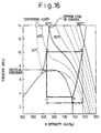
- the temperature and the pressure of the refrigerant at the outlet (the point C) of the gas cooler are detected by respective sensors, and on the basis of the aforementioned optimum line of control, determination of an optimum pressure in the high-pressure path is carried out with respect to the detected temperature of the refrigerant.
- the throttle means is controlled so as to adjustably change an actual pressure in the high-pressure path to the determined optimum pressure, and accordingly, the coefficient of performance (COP) of the refrigerating system is increased to the maximum while the energy consumption in the refrigerating system is reduced to the minimum.
- COP coefficient of performance
- the temperature and the pressure of the refrigerant at the outlet (the point C) of the gas cooler in the high-pressure path are detected, and the throttling means is regulated so that the pressure of the refrigerant at the outlet (the point C) of the gas cooler is varied to an optimum pressure corresponding to the detected temperature, and as a result, the maximum coefficient of performance (COP) and in turn, the minimum energy consumption of the supercritical refrigerating system are achieved.
- COP maximum coefficient of performance
- the throttling means In the supercritical refrigerating system for a vehicle, which requires a regulating operation of the throttling means, when an increase in the speed of rotation of the vehicle engine and in turn the rotating speed of the drive shaft of the refrigerant compressor (the variable displacement compressor) occur, a mass amount of the refrigerant supplied to the gas cooler is increased. Thus, a pressure of the refrigerant in the gas cooler (i.e., a pressure in the high-pressure path and a discharge pressure of the compressor) is increased. Further, as described hereinabove, since the throttling means is regulated so that the pressure at the outlet of the gas cooler is kept substantially constant, the path of the throttling means must be increased to prevent an increase in the pressure at the outlet of the gas cooler. Therefore, the operation of the throttling means to reduce the path thereof is often slow to result in that the control of the refrigerating performance cannot be quickly achieved.
- a further object of the present invention is to provide a refrigerant compressor suitable for being incorporated in a refrigerating system and, particularly, in a vehicle refrigerating system provided with the flow control valve capable of exhibiting the operating characteristics described in connection with the above second object.
- the flow control valve is provided with such a control characteristics that when the suction pressure is used as the set pressure of the pressure sensing member to variably control the displacement of the refrigerant compressor, in other words, when a control is made so as to reduce the displacement of the refrigerant compressor in response to a reduction in the suction pressure of the compressor below the set pressure of the sensing member, the set pressure of the pressure is gradually increased according to an increase in the discharge pressure.
- the gas cooler 2 is in turn connected to the expansion valve 3 via a fluid passage 6b.
- the expansion valve 3 is further connected to the evaporator 4 via a fluid passage 6c.
- the evaporator 4 is connected to the accumulator 5 via a fluid passage 6d, and the accumulator 5 is connected to a suction chamber 27 via a fluid passage 6e to form the closed refrigerant passage through which the refrigerant circulates.
- a sleeve element 21 is slidably mounted on a portion of the drive shaft 15 within the crank chamber 14, and the sleeve element 21 is provided with pivots 21a about which the cam plate 20 is pivotally mounted.
- a wobble plate 23 is non-rotatably mounted on the cam plate 20 via a thrust bearing 22 and other bearing means.
- the wobble plate 23 is provided with a rotation-preventing pin (not shown) fixedly connected thereto to be slid in an axial groove 11a formed in the front housing 11, so that the wobble plate 23 is prevented from rotating the rotation of the cam plate 20 and the drive shaft 15.
- a central discharge chamber 26 and a suction chamber 27 arranged radically around the discharge chamber 26.
- the respective cylinder bores 10a form compression chambers defining in front of working heads of the respective pistons 26, and the compression chambers are fluidly connected to the discharge chamber 26 via respective discharge ports formed in the valve plate 12.
- the respective discharge ports of the valve plate 12 are opened and closed by discharge valves of which the opening movement is controlled by a retainer plate 26a provided in the discharge chamber 26.
- the compression chambers of the respective cylinder bores 10a are fluidly connected to the suction chamber 27 via respective suction ports formed in the valve plate 12, and the suction ports are opened and closed by suction valves arranged on an inner face of the valve plate 12 facing the rear end of the cylinder block 10.
- the flow control valve 30 of the first embodiment is provided with a pressure-sensing member 32 arranged to receive and to sense a suction pressure (Ps) when it is introduced into the valve 30 via a pressure-sensing passage 31 (Fig. 1).
- the pressure-sensing member 32 is provided to move in a valve housing in response to a change in the suction pressure (Ps).
- the pressure-sensing member 32 might be formed by either a conventional diaphragm element or a conventional bellows member.
- the compressor 1 is operated on the basis of the aforementioned control characteristics of the flow control valve 30. Namely, when an actual or current suction pressure (Ps) of the refrigerant entering the suction chamber 27 is reduced to a pressure below a set pressure of the suction pressure (Ps), which is determined on the basis of the discharge pressure (Pd) of the refrigerant acting on the flow control valve 30, the valve element 33 increases the valve opening in the controlling passage 29 permitting the refrigerant under the discharge pressure (Pd) to flow from the discharge chamber 26 into the crank chamber 14. Therefore, the crank chamber pressure (Pc) in the crank chamber 14 is increased so that the angle of inclination of the cam plate 20 and the wobble plate 23 is reduced. Accordingly, the displacement of the compressor 1 is reduced.
- the set pressure value of the pressure-sensing member 32 of the flow control valve according to the second embodiment can basically vary to have a linear characteristic curve ascending from the left to the right, and operates in a similar way to the first embodiment so as to quickly reduce the displacement of the compressor 1 when an increase in the speed of rotation of a vehicle engine occurs. Further, as clearly shown in Fig 5, the set pressure value of the pressure-sensing member 32 of the flow control valve 30 of this embodiment can be varied by the solenoid 35 to have a variation band between two linear curves "A" and "B" to adjustably change the temperature of the air blown by the evaporator 4.
- the flow control valve 30 of this embodiment is different from the valve 30 of the previous sixth embodiment in that the set pressure value of a pressure-sensing member 32 of this embodiment can be varied by a solenoid 35 controlled externally. Therefore, due to adjustably varying the set pressure value (F) of the pressure-sensing member 32 by the operation of the solenoid 35, the flow of the refrigerant under a high pressure passing through the valve opening in the controlling passage 29 can be finely adjusted, and accordingly, a fine control of the climate control by the vehicle refrigerating system can be achieved.
Landscapes
- Engineering & Computer Science (AREA)
- Mechanical Engineering (AREA)
- General Engineering & Computer Science (AREA)
- Compressors, Vaccum Pumps And Other Relevant Systems (AREA)
- Control Of Positive-Displacement Pumps (AREA)
Priority Applications (1)
| Application Number | Priority Date | Filing Date | Title |
|---|---|---|---|
| EP05025382.2A EP1635058B1 (fr) | 1998-04-16 | 1999-04-16 | Soupape de contrôle de débit d'un compresseur à capacité variable pour réfrigérant |
Applications Claiming Priority (2)
| Application Number | Priority Date | Filing Date | Title |
|---|---|---|---|
| JP10671798 | 1998-04-16 | ||
| JP10671798A JP3900669B2 (ja) | 1998-04-16 | 1998-04-16 | 制御弁及び可変容量型圧縮機 |
Related Child Applications (1)
| Application Number | Title | Priority Date | Filing Date |
|---|---|---|---|
| EP05025382.2A Division EP1635058B1 (fr) | 1998-04-16 | 1999-04-16 | Soupape de contrôle de débit d'un compresseur à capacité variable pour réfrigérant |
Publications (3)
| Publication Number | Publication Date |
|---|---|
| EP0952344A2 true EP0952344A2 (fr) | 1999-10-27 |
| EP0952344A3 EP0952344A3 (fr) | 2000-03-01 |
| EP0952344B1 EP0952344B1 (fr) | 2006-02-01 |
Family
ID=14440717
Family Applications (2)
| Application Number | Title | Priority Date | Filing Date |
|---|---|---|---|
| EP05025382.2A Expired - Lifetime EP1635058B1 (fr) | 1998-04-16 | 1999-04-16 | Soupape de contrôle de débit d'un compresseur à capacité variable pour réfrigérant |
| EP99106298A Expired - Lifetime EP0952344B1 (fr) | 1998-04-16 | 1999-04-16 | Soupape de contrôle de débit d'un compresseur à capacité variable pour réfrigérant |
Family Applications Before (1)
| Application Number | Title | Priority Date | Filing Date |
|---|---|---|---|
| EP05025382.2A Expired - Lifetime EP1635058B1 (fr) | 1998-04-16 | 1999-04-16 | Soupape de contrôle de débit d'un compresseur à capacité variable pour réfrigérant |
Country Status (4)
| Country | Link |
|---|---|
| US (1) | US6260369B1 (fr) |
| EP (2) | EP1635058B1 (fr) |
| JP (1) | JP3900669B2 (fr) |
| DE (1) | DE69929643T2 (fr) |
Cited By (5)
| Publication number | Priority date | Publication date | Assignee | Title |
|---|---|---|---|---|
| EP0952412A3 (fr) * | 1998-04-16 | 2002-01-16 | Kabushiki Kaisha Toyota Jidoshokki | Système frigorifique et procédé pour son fonctionnement |
| US6589020B2 (en) | 2000-07-06 | 2003-07-08 | Kabushiki Kaisha Toyoda Jidoshokki Seisakusho | Control valve for variable displacement compressor |
| EP1148242A3 (fr) * | 2000-04-18 | 2003-07-16 | Kabushiki Kaisha Toyota Jidoshokki | Soupape de commande d'un compresseur à capacité variable |
| EP1116882A3 (fr) * | 2000-01-14 | 2003-08-13 | Kabushiki Kaisha Toyota Jidoshokki | Compresseur à capacité variable et climatisation |
| EP1442906A3 (fr) * | 2003-02-03 | 2005-12-28 | Calsonic Kansei Corporation | Appareil de climatisation avec un réfrigérant supercritique pour véhicules |
Families Citing this family (13)
| Publication number | Priority date | Publication date | Assignee | Title |
|---|---|---|---|---|
| JPH11313094A (ja) | 1998-04-27 | 1999-11-09 | Yazaki Corp | リング式ネットワークの監視システム |
| JP3780784B2 (ja) | 1999-11-25 | 2006-05-31 | 株式会社豊田自動織機 | 空調装置および容量可変型圧縮機の制御弁 |
| JP2003002048A (ja) * | 2000-08-28 | 2003-01-08 | Denso Corp | 車両用空調装置 |
| JP2005257240A (ja) * | 2004-03-15 | 2005-09-22 | Sanyo Electric Co Ltd | 遷臨界冷凍装置 |
| US20060230773A1 (en) * | 2005-04-14 | 2006-10-19 | Carrier Corporation | Method for determining optimal coefficient of performance in a transcritical vapor compression system |
| JP4865333B2 (ja) * | 2006-01-06 | 2012-02-01 | サンデン株式会社 | 容量可変型圧縮機 |
| US7611335B2 (en) * | 2006-03-15 | 2009-11-03 | Delphi Technologies, Inc. | Two set-point pilot piston control valve |
| JP4599327B2 (ja) * | 2006-05-23 | 2010-12-15 | サンデン株式会社 | 可変容量圧縮機 |
| JP5075425B2 (ja) | 2007-02-19 | 2012-11-21 | サンデン株式会社 | 可変容量圧縮機の容量制御弁 |
| JP2008032026A (ja) * | 2007-10-22 | 2008-02-14 | Tgk Co Ltd | 冷凍サイクルの圧縮容量制御装置 |
| EP2535667B1 (fr) * | 2010-02-12 | 2018-09-26 | Mitsubishi Electric Corporation | Dispositif à cycle frigorifique |
| KR101689241B1 (ko) * | 2012-12-12 | 2016-12-23 | 이구루코교 가부시기가이샤 | 용량 제어 밸브 |
| US10041552B2 (en) * | 2015-07-16 | 2018-08-07 | Ford Global Technologies, Llc | Methods and systems for controlling a vehicle air conditioner using a pressure sensor located within a compressor |
Citations (1)
| Publication number | Priority date | Publication date | Assignee | Title |
|---|---|---|---|---|
| EP0604417B1 (fr) | 1991-09-16 | 1996-04-17 | Sinvent A/S | Regulation de pression en partie haute pression d'un cycle de carnot renverse transcritique |
Family Cites Families (8)
| Publication number | Priority date | Publication date | Assignee | Title |
|---|---|---|---|---|
| JPS62253970A (ja) | 1986-04-25 | 1987-11-05 | Toyota Autom Loom Works Ltd | 可変容量圧縮機 |
| US4732544A (en) | 1986-06-12 | 1988-03-22 | Diesel Kiki Co., Ltd. | Variable capacity wobble plate compressor |
| JP2551416B2 (ja) * | 1986-10-07 | 1996-11-06 | 株式会社ゼクセル | 自動車用空調装置 |
| JPH01142276A (ja) | 1987-11-27 | 1989-06-05 | Sanden Corp | 容量可変型斜板式圧縮機 |
| JP3082485B2 (ja) | 1992-12-11 | 2000-08-28 | 株式会社豊田自動織機製作所 | 揺動斜板式可変容量圧縮機 |
| DE4432272C2 (de) | 1994-09-09 | 1997-05-15 | Daimler Benz Ag | Verfahren zum Betreiben einer Kälteerzeugungsanlage für das Klimatisieren von Fahrzeugen und eine Kälteerzeugungsanlage zur Durchführung desselben |
| CH690189A5 (de) | 1995-03-10 | 2000-05-31 | Daimler Benz Ag | Verfahren zur Regelung der Leistung einer Anlage für die Kühlung des Fahrgastraumes eines Kraftfahrzeuges. |
| CH689826A5 (de) | 1995-05-10 | 1999-12-15 | Daimler Benz Ag | Fahrzeug-Klimaanlage. |
-
1998
- 1998-04-16 JP JP10671798A patent/JP3900669B2/ja not_active Expired - Lifetime
-
1999
- 1999-04-13 US US09/290,972 patent/US6260369B1/en not_active Expired - Lifetime
- 1999-04-16 EP EP05025382.2A patent/EP1635058B1/fr not_active Expired - Lifetime
- 1999-04-16 DE DE69929643T patent/DE69929643T2/de not_active Expired - Lifetime
- 1999-04-16 EP EP99106298A patent/EP0952344B1/fr not_active Expired - Lifetime
Patent Citations (1)
| Publication number | Priority date | Publication date | Assignee | Title |
|---|---|---|---|---|
| EP0604417B1 (fr) | 1991-09-16 | 1996-04-17 | Sinvent A/S | Regulation de pression en partie haute pression d'un cycle de carnot renverse transcritique |
Cited By (5)
| Publication number | Priority date | Publication date | Assignee | Title |
|---|---|---|---|---|
| EP0952412A3 (fr) * | 1998-04-16 | 2002-01-16 | Kabushiki Kaisha Toyota Jidoshokki | Système frigorifique et procédé pour son fonctionnement |
| EP1116882A3 (fr) * | 2000-01-14 | 2003-08-13 | Kabushiki Kaisha Toyota Jidoshokki | Compresseur à capacité variable et climatisation |
| EP1148242A3 (fr) * | 2000-04-18 | 2003-07-16 | Kabushiki Kaisha Toyota Jidoshokki | Soupape de commande d'un compresseur à capacité variable |
| US6589020B2 (en) | 2000-07-06 | 2003-07-08 | Kabushiki Kaisha Toyoda Jidoshokki Seisakusho | Control valve for variable displacement compressor |
| EP1442906A3 (fr) * | 2003-02-03 | 2005-12-28 | Calsonic Kansei Corporation | Appareil de climatisation avec un réfrigérant supercritique pour véhicules |
Also Published As
| Publication number | Publication date |
|---|---|
| EP1635058A1 (fr) | 2006-03-15 |
| EP0952344B1 (fr) | 2006-02-01 |
| DE69929643T2 (de) | 2006-12-07 |
| JP3900669B2 (ja) | 2007-04-04 |
| US6260369B1 (en) | 2001-07-17 |
| DE69929643D1 (de) | 2006-04-13 |
| JPH11294328A (ja) | 1999-10-26 |
| EP0952344A3 (fr) | 2000-03-01 |
| EP1635058B1 (fr) | 2016-01-20 |
Similar Documents
| Publication | Publication Date | Title |
|---|---|---|
| US6105380A (en) | Refrigerating system and method of operating the same | |
| US6260369B1 (en) | Flow control valve for a variable displacement refrigerant compressor | |
| KR100360006B1 (ko) | 초 임계 증기 압축 장치 | |
| US7841193B2 (en) | Refrigerant flow-amount controlling device and ejector refrigerant cycle system using the same | |
| EP0309242B1 (fr) | Système frigorifique muni d'un compresseur avec un mécanisme de déplacement variable commandé du dedans et du dehors | |
| JP4285060B2 (ja) | 蒸気圧縮式冷凍機 | |
| US5823000A (en) | Refrigerant circuit with fluid flow control mechanism | |
| JPH10115470A (ja) | 蒸気圧縮式冷凍サイクル | |
| US6997001B2 (en) | Method of operating a refrigeration cycle | |
| JP2001012358A (ja) | 冷凍サイクルの可変容量制御装置 | |
| JP4207235B2 (ja) | 蒸気圧縮式冷凍サイクル | |
| US6231314B1 (en) | Variable displacement compressor | |
| US20030035733A1 (en) | Compression capacity control device for refrigeration cycle | |
| JPH1089785A (ja) | 蒸気圧縮式冷凍サイクル | |
| JP3752816B2 (ja) | 可変容量型圧縮機の動作制御方法及び動作制御装置 | |
| JPH03134268A (ja) | 可変容量式斜板型圧縮機 | |
| JP2009002649A (ja) | エジェクタ式冷凍サイクル | |
| JPH04321779A (ja) | 斜板型可変容量圧縮機 | |
| JP4118413B2 (ja) | 容量可変斜板式コンプレッサ | |
| JPH11223179A (ja) | 可変容量型圧縮機の動作制御方法及び動作制御装置 | |
| JP2010018060A (ja) | 車両用冷凍回路 | |
| JPH06241580A (ja) | 冷凍サイクル装置 | |
| JPS6390681A (ja) | 可変容量圧縮機 | |
| JPS6291672A (ja) | 可変容量圧縮機 | |
| JPH0741359U (ja) | 自動車用空気調和装置 |
Legal Events
| Date | Code | Title | Description |
|---|---|---|---|
| PUAI | Public reference made under article 153(3) epc to a published international application that has entered the european phase |
Free format text: ORIGINAL CODE: 0009012 |
|
| 17P | Request for examination filed |
Effective date: 19990416 |
|
| AK | Designated contracting states |
Kind code of ref document: A2 Designated state(s): DE FR IT |
|
| AX | Request for extension of the european patent |
Free format text: AL;LT;LV;MK;RO;SI |
|
| PUAL | Search report despatched |
Free format text: ORIGINAL CODE: 0009013 |
|
| AK | Designated contracting states |
Kind code of ref document: A3 Designated state(s): AT BE CH CY DE DK ES FI FR GB GR IE IT LI LU MC NL PT SE |
|
| AX | Request for extension of the european patent |
Free format text: AL;LT;LV;MK;RO;SI |
|
| AKX | Designation fees paid |
Free format text: DE FR IT |
|
| RAP1 | Party data changed (applicant data changed or rights of an application transferred) |
Owner name: KABUSHIKI KAISHA TOYOTA JIDOSHOKKI |
|
| 17Q | First examination report despatched |
Effective date: 20040903 |
|
| GRAP | Despatch of communication of intention to grant a patent |
Free format text: ORIGINAL CODE: EPIDOSNIGR1 |
|
| GRAS | Grant fee paid |
Free format text: ORIGINAL CODE: EPIDOSNIGR3 |
|
| GRAA | (expected) grant |
Free format text: ORIGINAL CODE: 0009210 |
|
| RIN1 | Information on inventor provided before grant (corrected) |
Inventor name: FUJII, TOSHIRO Inventor name: KOIDE, TATSUYA Inventor name: MURAKAMI, KAZUO Inventor name: YOKOMACHI, NAOYA |
|
| AK | Designated contracting states |
Kind code of ref document: B1 Designated state(s): DE FR IT |
|
| REF | Corresponds to: |
Ref document number: 69929643 Country of ref document: DE Date of ref document: 20060413 Kind code of ref document: P |
|
| ET | Fr: translation filed | ||
| PLBE | No opposition filed within time limit |
Free format text: ORIGINAL CODE: 0009261 |
|
| STAA | Information on the status of an ep patent application or granted ep patent |
Free format text: STATUS: NO OPPOSITION FILED WITHIN TIME LIMIT |
|
| 26N | No opposition filed |
Effective date: 20061103 |
|
| REG | Reference to a national code |
Ref country code: DE Ref legal event code: R082 Ref document number: 69929643 Country of ref document: DE Representative=s name: HOEGER, STELLRECHT & PARTNER PATENTANWAELTE MB, DE |
|
| REG | Reference to a national code |
Ref country code: FR Ref legal event code: PLFP Year of fee payment: 18 |
|
| REG | Reference to a national code |
Ref country code: FR Ref legal event code: PLFP Year of fee payment: 19 |
|
| REG | Reference to a national code |
Ref country code: FR Ref legal event code: PLFP Year of fee payment: 20 |
|
| PGFP | Annual fee paid to national office [announced via postgrant information from national office to epo] |
Ref country code: FR Payment date: 20180315 Year of fee payment: 20 |
|
| PGFP | Annual fee paid to national office [announced via postgrant information from national office to epo] |
Ref country code: DE Payment date: 20180404 Year of fee payment: 20 |
|
| PGFP | Annual fee paid to national office [announced via postgrant information from national office to epo] |
Ref country code: IT Payment date: 20180420 Year of fee payment: 20 |
|
| REG | Reference to a national code |
Ref country code: DE Ref legal event code: R071 Ref document number: 69929643 Country of ref document: DE |