EP0952441B1 - Procédé pour déterminer la fluorescence induite par le soleil - Google Patents
Procédé pour déterminer la fluorescence induite par le soleil Download PDFInfo
- Publication number
- EP0952441B1 EP0952441B1 EP99107749A EP99107749A EP0952441B1 EP 0952441 B1 EP0952441 B1 EP 0952441B1 EP 99107749 A EP99107749 A EP 99107749A EP 99107749 A EP99107749 A EP 99107749A EP 0952441 B1 EP0952441 B1 EP 0952441B1
- Authority
- EP
- European Patent Office
- Prior art keywords
- radiance
- fluorescence
- absorption band
- sensor
- atmosphere
- Prior art date
- Legal status (The legal status is an assumption and is not a legal conclusion. Google has not performed a legal analysis and makes no representation as to the accuracy of the status listed.)
- Expired - Lifetime
Links
Images


Classifications
-
- G—PHYSICS
- G01—MEASURING; TESTING
- G01N—INVESTIGATING OR ANALYSING MATERIALS BY DETERMINING THEIR CHEMICAL OR PHYSICAL PROPERTIES
- G01N21/00—Investigating or analysing materials by the use of optical means, i.e. using sub-millimetre waves, infrared, visible or ultraviolet light
- G01N21/62—Systems in which the material investigated is excited whereby it emits light or causes a change in wavelength of the incident light
- G01N21/63—Systems in which the material investigated is excited whereby it emits light or causes a change in wavelength of the incident light optically excited
- G01N21/64—Fluorescence; Phosphorescence
- G01N21/6486—Measuring fluorescence of biological material, e.g. DNA, RNA, cells
-
- G—PHYSICS
- G01—MEASURING; TESTING
- G01N—INVESTIGATING OR ANALYSING MATERIALS BY DETERMINING THEIR CHEMICAL OR PHYSICAL PROPERTIES
- G01N21/00—Investigating or analysing materials by the use of optical means, i.e. using sub-millimetre waves, infrared, visible or ultraviolet light
- G01N21/62—Systems in which the material investigated is excited whereby it emits light or causes a change in wavelength of the incident light
- G01N21/63—Systems in which the material investigated is excited whereby it emits light or causes a change in wavelength of the incident light optically excited
- G01N21/64—Fluorescence; Phosphorescence
- G01N21/645—Specially adapted constructive features of fluorimeters
- G01N21/6456—Spatial resolved fluorescence measurements; Imaging
-
- G—PHYSICS
- G01—MEASURING; TESTING
- G01N—INVESTIGATING OR ANALYSING MATERIALS BY DETERMINING THEIR CHEMICAL OR PHYSICAL PROPERTIES
- G01N21/00—Investigating or analysing materials by the use of optical means, i.e. using sub-millimetre waves, infrared, visible or ultraviolet light
- G01N21/62—Systems in which the material investigated is excited whereby it emits light or causes a change in wavelength of the incident light
- G01N21/63—Systems in which the material investigated is excited whereby it emits light or causes a change in wavelength of the incident light optically excited
- G01N21/64—Fluorescence; Phosphorescence
- G01N2021/6417—Spectrofluorimetric devices
- G01N2021/6421—Measuring at two or more wavelengths
-
- G—PHYSICS
- G01—MEASURING; TESTING
- G01N—INVESTIGATING OR ANALYSING MATERIALS BY DETERMINING THEIR CHEMICAL OR PHYSICAL PROPERTIES
- G01N21/00—Investigating or analysing materials by the use of optical means, i.e. using sub-millimetre waves, infrared, visible or ultraviolet light
- G01N21/62—Systems in which the material investigated is excited whereby it emits light or causes a change in wavelength of the incident light
- G01N21/63—Systems in which the material investigated is excited whereby it emits light or causes a change in wavelength of the incident light optically excited
- G01N21/64—Fluorescence; Phosphorescence
- G01N2021/6417—Spectrofluorimetric devices
- G01N2021/6426—Determining Fraunhofer lines
-
- G—PHYSICS
- G01—MEASURING; TESTING
- G01N—INVESTIGATING OR ANALYSING MATERIALS BY DETERMINING THEIR CHEMICAL OR PHYSICAL PROPERTIES
- G01N2201/00—Features of devices classified in G01N21/00
- G01N2201/06—Illumination; Optics
- G01N2201/061—Sources
- G01N2201/0616—Ambient light is used
Definitions
- the invention relates to a method for deriving from Sunlight excited fluorescent light from a measurement object a beam density measurement carried out by means of a sensor within one atmospheric absorption band and one further beam density measurement carried out by means of the sensor, made outside of the atmospheric absorption band becomes.
- chlorophyll fluorescence becomes a characterization the state of a photosynthetic apparatus used. Therefore a method was developed, the fluorescence derived from the reflection signal. This method is used in described below.
- a detection of the fluorescence stimulated by sunlight in the Range of atmospheric Fraunhofer lines, i.e. the atmospheric Absorption bands, is using the Fraunhofer Line discriminator method not over long distances possible because the incident light in the area of the sensor detector is detected. This differs in the area of atmospheric Fraunhofer lines, however, considerable and unpredictable from that on the measurement object level, since the atmosphere between the sensor detector and the measurement object strong fluctuations in their optical properties is subject.
- the invention is based, without the aid of the task an additional light source a method for deriving sunlight-excited fluorescent light from radiance measurements continue to develop so that the influence of the atmosphere between object and sensor can be corrected.
- the method according to the invention is based on the “filling” of broadband atmospheric absorption bands in the reflection signal by fluorescent light. It is assumed here that the radiance L ⁇ at the detector is composed as follows:
- R denotes the unknown reflectance of the substance to be investigated, which is assumed to be spectrally independent in the spectral range under investigation.
- L 0 / ⁇ the radiance of sunlight on the object
- L fluorescence the fluorescence beam density
- T ⁇ the transmittance of the atmosphere between the object and the sensor
- L air / ⁇ the radiance of the so-called " Heillichts ", ie the light scattered directly from the atmosphere between the object and sensor to the sensor.
- the beam densities are advantageously measured at two closely spaced wavelengths, namely a beam density within an atmospheric absorption band and another outside the atmospheric absorption band, so that the spectral independence of the reflectance R and the fluorescence beam density L fluorescence is ensured.
- a spectral resolution of 10 nm is sufficient in the region of the O 2 A absorption band around 762 nm. This enables the use of less sensitive detectors or measurements over larger distances.
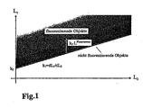
- radiance L 1 shows a radiance L 1 on the ordinate and a radiance L 2 on the abscissa.
- the radiance of non-fluorescent objects lies on a straight line.
- the fluorescent objects are in the upper half-plane.
- the distance in the ordinate or L 1 direction is equal to k 3 ⁇ L fluorescence . If the radiance L 1 is plotted against the radiance L 2 of non-fluorescent objects, then k 1 corresponds to the slope and k 2 to the intercept of the best-fit line.
- the fluorescence beam density of fluorescent objects can then be calculated from the above equation.
- k 3 cannot be derived solely from the measurements of the beam densities L 1 and L 2 .
- the fluorescence beam density can therefore only be derived in relative units. Soil measurements must be available for an absolute specification, or the transmissivity of the atmosphere T 1 and T 2 must be known from other measurements or simulation calculations.
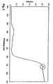
- FIG. 2 shows the time course of the reflected radiance of vegetation measured with the aid of the spectrometer in ( L 1 ) or before ( L 2 ) the O 2 A absorption band.
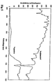
- Figure 3 the temporal course of the fluorescence derived therefrom according to Eq. (2) and measured with a PAM fluorometer is plotted. The two measurements agree very well despite the different sized measuring area.
- a method is thus created to derive sun-excited fluorescence from reflection measurements. This makes it possible to get the fluorescence from passive Derive measurements with simple spectrometers. This in turn enables the use of aircraft or satellite-borne Spectrometers for large-scale detection of chlorophyll fluorescence and thus the photosynthetic state the vegetation.
Landscapes
- Health & Medical Sciences (AREA)
- Life Sciences & Earth Sciences (AREA)
- Biochemistry (AREA)
- Nuclear Medicine, Radiotherapy & Molecular Imaging (AREA)
- Physics & Mathematics (AREA)
- Chemical & Material Sciences (AREA)
- Analytical Chemistry (AREA)
- General Health & Medical Sciences (AREA)
- General Physics & Mathematics (AREA)
- Immunology (AREA)
- Pathology (AREA)
- Biomedical Technology (AREA)
- Molecular Biology (AREA)
- Engineering & Computer Science (AREA)
- Investigating, Analyzing Materials By Fluorescence Or Luminescence (AREA)
Claims (3)
- Procédé pour dériver une lumière de fluorescence, induite par la lumière solaire, d'un objet de mesure à partir d'une mesure de densité de rayonnement exécutée à l'aide d'un capteur, à l'intérieur d'une bande d'absorption atmosphérique et d'une autre mesure de densité de rayonnement réalisée à l'aide du capteur et qui est effectuée à l'extérieur de la bande d'absorption atmosphérique, caractérisé en ce que dans le cas des mesures de densité de rayonnement pour la correction de l'influence, produite par l'exploration à distance, de l'atmosphère entre le capteur et l'objet de mesure, on exécute en supplément des mesures de densité de rayonnement sur des objets non fluorescents, et on détermine la densité de rayonnement de fluorescente Lfluorescence d'objets fluorescents sur la base de la relation d'évaluation
- Procédé selon la revendication 1, caractérisé en ce que pour la détermination de la grandeur constante k3 et par conséquent également d'une indication de valeur absolue de la densité du rayonnement de fluorescence Lfluorescence d'objets fluorescents on réalise également des mesures au sol et d'autres mesures ou des calculs de simulation, à partir desquels on connaít les degrés de transmission T1 et T2 de l'atmosphère.
- Procédé selon la revendication 1 ou 2, caractérisé en ce que la lumière de fluorescence, induite par la lumière solaire, d'objets fluorescents est dérivée de données d'image, qui sont obtenues à l'aide de spectromètres de formation d'images, utilisés comme capteurs et placés dans un avion ou dans un satellite, en tant que capteurs.
Applications Claiming Priority (2)
| Application Number | Priority Date | Filing Date | Title |
|---|---|---|---|
| DE19817843A DE19817843B4 (de) | 1998-04-22 | 1998-04-22 | Verfahren zum Ableiten sonnenangeregten Fluoreszenzlichts aus Strahldichtemessungen |
| DE19817843 | 1998-04-22 |
Publications (2)
| Publication Number | Publication Date |
|---|---|
| EP0952441A1 EP0952441A1 (fr) | 1999-10-27 |
| EP0952441B1 true EP0952441B1 (fr) | 2002-07-03 |
Family
ID=7865348
Family Applications (1)
| Application Number | Title | Priority Date | Filing Date |
|---|---|---|---|
| EP99107749A Expired - Lifetime EP0952441B1 (fr) | 1998-04-22 | 1999-04-19 | Procédé pour déterminer la fluorescence induite par le soleil |
Country Status (3)
| Country | Link |
|---|---|
| US (1) | US6329660B1 (fr) |
| EP (1) | EP0952441B1 (fr) |
| DE (1) | DE19817843B4 (fr) |
Families Citing this family (10)
| Publication number | Priority date | Publication date | Assignee | Title |
|---|---|---|---|---|
| CN100338444C (zh) * | 2003-06-13 | 2007-09-19 | 上海爱普特仪器有限公司 | 一种激光强度调节装置 |
| WO2012001171A1 (fr) * | 2010-07-02 | 2012-01-05 | Georg Fritzmeier Gmbh & Co. Kg | Système de mesure et procédé pour déterminer la teneur en azote de plantes |
| CN104897674B (zh) * | 2015-06-08 | 2017-09-01 | 云南农业大学 | 一种模拟测定林下阴生植物对光斑响应特征的方法 |
| CN105486673B (zh) * | 2016-01-27 | 2020-03-10 | 北京师范大学 | 一种叶绿素荧光自动化监测系统 |
| CN105548122B (zh) * | 2016-01-27 | 2020-04-17 | 北京师范大学 | 一种叶绿素荧光分时监测系统 |
| CN107238435B (zh) * | 2017-06-07 | 2018-06-12 | 江苏省无线电科学研究所有限公司 | 太阳辐射通量垂直廓线探测仪 |
| IT201900020174A1 (it) * | 2019-10-31 | 2021-05-01 | Consiglio Nazionale Ricerche | Dispositivo di calibrazione per la misura della fluorescenza della clorofilla indotta dalla luce solare |
| CN115843333A (zh) * | 2020-06-12 | 2023-03-24 | 新南创新私人有限公司 | 光伏模块的室外光致发光成像 |
| EP4074164B1 (fr) * | 2021-04-12 | 2024-01-03 | Heliospectra AB (publ) | Contrôle de l'intensité lumineuse dans un espace de culture fermé |
| DE102023104746A1 (de) * | 2023-02-27 | 2024-08-29 | Deutsches Zentrum für Luft- und Raumfahrt e.V. | Detektorvorrichtung zum erfassen von fluoreszenzlicht |
Family Cites Families (6)
| Publication number | Priority date | Publication date | Assignee | Title |
|---|---|---|---|---|
| US3598994A (en) * | 1968-09-19 | 1971-08-10 | Perkin Elmer Corp | Method and apparatus for sensing fluorescent substances |
| US4708475A (en) * | 1983-06-30 | 1987-11-24 | Atlantic Richfield Company | Portable luminescence sensor |
| US4671662A (en) * | 1985-06-18 | 1987-06-09 | Atlantic Richfield Company | Luminescense and reflectance detection radiometer with changeable optical assembly |
| US5062713A (en) * | 1989-09-06 | 1991-11-05 | The Dow Company | Method for determining the residence time distribution of a polymer extruder |
| US5298741A (en) * | 1993-01-13 | 1994-03-29 | Trustees Of Tufts College | Thin film fiber optic sensor array and apparatus for concurrent viewing and chemical sensing of a sample |
| US5567947A (en) * | 1995-06-01 | 1996-10-22 | Aerodyne Research, Inc. | Spectral line discriminator for passive detection of fluorescence |
-
1998
- 1998-04-22 DE DE19817843A patent/DE19817843B4/de not_active Expired - Fee Related
-
1999
- 1999-04-19 EP EP99107749A patent/EP0952441B1/fr not_active Expired - Lifetime
- 1999-04-20 US US09/294,357 patent/US6329660B1/en not_active Expired - Fee Related
Also Published As
| Publication number | Publication date |
|---|---|
| EP0952441A1 (fr) | 1999-10-27 |
| DE19817843A1 (de) | 1999-11-04 |
| DE19817843B4 (de) | 2006-06-08 |
| US6329660B1 (en) | 2001-12-11 |
Similar Documents
| Publication | Publication Date | Title |
|---|---|---|
| EP0534166B1 (fr) | Procédé et dispositif pour la détermination quantitatif des substances optiquement actif | |
| DE102007032849A1 (de) | Messeinrichtung und Verfahren zur optischen Konzentrationsbestimmung von Blutzucker und/oder Laktat in biologischen Systemen | |
| EP3051271A1 (fr) | Procédé de détermination de lipides et d'autres substances interférentes dans des échantillons de liquide corporel | |
| DE1026555B (de) | Verfahren und Vorrichtung fuer die spektrochemische Analyse | |
| DE102008009189B4 (de) | Nichtdispersiver Infrarot-Gasanalysator | |
| WO2006035012A1 (fr) | Tete de mesure spectrometrique pour moissonneuses et autres machines agricoles | |
| EP0952441B1 (fr) | Procédé pour déterminer la fluorescence induite par le soleil | |
| EP2549264A1 (fr) | Procédé et système de détermination de la concentration de substances dans des liquides corporels | |
| WO2007107366A1 (fr) | Dispositif d'analyse spectroscopique d'un gaz | |
| DE69926983T2 (de) | Verfahren und Vorrichtung zur dynamischen Lichtstreuung | |
| EP3017292A1 (fr) | Procédé de détermination de la concentration d'une matière dans un contenant déformable | |
| DE112020002033T5 (de) | Analysesystem und Analyseverfahren | |
| EP3671184B1 (fr) | Dispositif de détection d'alcool doté de canaux de mesure redondants et procédé pour détecter d'alcool | |
| DE3938142C2 (fr) | ||
| DE102021100321B4 (de) | SPR-Sensoreinheit und Verfahren zur Bestimmung des Brechungsindex eines Proben-mediums sowie Messeinrichtung zur Erfassung der Dichte eines Messmediums | |
| DE3204146A1 (de) | Verfahren zur messung der zusammensetzung und oertlichen konzentration von stoffen an oberflaechen | |
| Röver et al. | Indirect determination of leaf area index of sugar beet canopies in comparison to direct measurement | |
| EP2261641A2 (fr) | Dispositif et procédé de détermination du rendement quantique de la luminescence d'un échantillon luminescent | |
| EP3816609B1 (fr) | Dispositif et procédé de détection à distance d'un gaz cible | |
| DE102017130988B4 (de) | Vorrichtungen und verfahren zur nutzung des photoakustischen effekts | |
| DE102012019471A1 (de) | Vorrichtung und Verfahren zum Ermitteln von Stoffeigenschaften | |
| DE102015214926A1 (de) | Urinanalyse im Durchfluss in Echtzeit mittels spektraler Messung | |
| DE19716061C1 (de) | Infrarotoptisches Gasmeßsystem | |
| DE69318632T2 (de) | Einrichtung zur Messung von Teilchen | |
| DE60126600T2 (de) | Analyseverfahren für stoffmischungen |
Legal Events
| Date | Code | Title | Description |
|---|---|---|---|
| PUAI | Public reference made under article 153(3) epc to a published international application that has entered the european phase |
Free format text: ORIGINAL CODE: 0009012 |
|
| AK | Designated contracting states |
Kind code of ref document: A1 Designated state(s): FR GB |
|
| AX | Request for extension of the european patent |
Free format text: AL;LT;LV;MK;RO;SI |
|
| 17P | Request for examination filed |
Effective date: 19991217 |
|
| AKX | Designation fees paid |
Free format text: FR GB |
|
| REG | Reference to a national code |
Ref country code: DE Ref legal event code: 8566 |
|
| 17Q | First examination report despatched |
Effective date: 20010110 |
|
| GRAG | Despatch of communication of intention to grant |
Free format text: ORIGINAL CODE: EPIDOS AGRA |
|
| GRAG | Despatch of communication of intention to grant |
Free format text: ORIGINAL CODE: EPIDOS AGRA |
|
| GRAH | Despatch of communication of intention to grant a patent |
Free format text: ORIGINAL CODE: EPIDOS IGRA |
|
| RTI1 | Title (correction) |
Free format text: METHOD FOR MEASURING SUNLIGHT INDUCED FLUORESCENCE |
|
| GRAH | Despatch of communication of intention to grant a patent |
Free format text: ORIGINAL CODE: EPIDOS IGRA |
|
| GRAA | (expected) grant |
Free format text: ORIGINAL CODE: 0009210 |
|
| AK | Designated contracting states |
Kind code of ref document: B1 Designated state(s): FR GB |
|
| GBT | Gb: translation of ep patent filed (gb section 77(6)(a)/1977) |
Effective date: 20020703 |
|
| ET | Fr: translation filed | ||
| PLBE | No opposition filed within time limit |
Free format text: ORIGINAL CODE: 0009261 |
|
| STAA | Information on the status of an ep patent application or granted ep patent |
Free format text: STATUS: NO OPPOSITION FILED WITHIN TIME LIMIT |
|
| 26N | No opposition filed |
Effective date: 20030404 |
|
| PGFP | Annual fee paid to national office [announced via postgrant information from national office to epo] |
Ref country code: GB Payment date: 20070425 Year of fee payment: 9 |
|
| PGFP | Annual fee paid to national office [announced via postgrant information from national office to epo] |
Ref country code: FR Payment date: 20070418 Year of fee payment: 9 |
|
| GBPC | Gb: european patent ceased through non-payment of renewal fee |
Effective date: 20080419 |
|
| REG | Reference to a national code |
Ref country code: FR Ref legal event code: ST Effective date: 20081231 |
|
| PG25 | Lapsed in a contracting state [announced via postgrant information from national office to epo] |
Ref country code: FR Free format text: LAPSE BECAUSE OF NON-PAYMENT OF DUE FEES Effective date: 20080430 |
|
| PG25 | Lapsed in a contracting state [announced via postgrant information from national office to epo] |
Ref country code: GB Free format text: LAPSE BECAUSE OF NON-PAYMENT OF DUE FEES Effective date: 20080419 |