EP0952443A1 - Vorrichtung zum Detektieren von Fehlern im Hals- und Endbereich einer geformten Flasche - Google Patents
Vorrichtung zum Detektieren von Fehlern im Hals- und Endbereich einer geformten Flasche Download PDFInfo
- Publication number
- EP0952443A1 EP0952443A1 EP99108092A EP99108092A EP0952443A1 EP 0952443 A1 EP0952443 A1 EP 0952443A1 EP 99108092 A EP99108092 A EP 99108092A EP 99108092 A EP99108092 A EP 99108092A EP 0952443 A1 EP0952443 A1 EP 0952443A1
- Authority
- EP
- European Patent Office
- Prior art keywords
- light
- neck
- finish portion
- glass bottle
- emitting
- Prior art date
- Legal status (The legal status is an assumption and is not a legal conclusion. Google has not performed a legal analysis and makes no representation as to the accuracy of the status listed.)
- Granted
Links
- 239000011521 glass Substances 0.000 title claims abstract description 83
- 238000001514 detection method Methods 0.000 claims abstract description 78
- 238000003491 array Methods 0.000 claims abstract description 5
- 238000012545 processing Methods 0.000 claims description 10
- 230000000873 masking effect Effects 0.000 claims description 5
- 230000002950 deficient Effects 0.000 abstract description 19
- 210000003739 neck Anatomy 0.000 description 87
- 238000010586 diagram Methods 0.000 description 10
- 230000008859 change Effects 0.000 description 4
- 230000003287 optical effect Effects 0.000 description 4
- 230000007246 mechanism Effects 0.000 description 3
- 230000035945 sensitivity Effects 0.000 description 3
- 230000007547 defect Effects 0.000 description 2
- 230000000593 degrading effect Effects 0.000 description 2
- 230000004069 differentiation Effects 0.000 description 2
- 230000003028 elevating effect Effects 0.000 description 2
- 230000006870 function Effects 0.000 description 2
- 238000000034 method Methods 0.000 description 2
- 230000004044 response Effects 0.000 description 2
- 238000012546 transfer Methods 0.000 description 2
- 238000004458 analytical method Methods 0.000 description 1
- 230000008901 benefit Effects 0.000 description 1
- 239000003086 colorant Substances 0.000 description 1
- 239000007799 cork Substances 0.000 description 1
- 238000013480 data collection Methods 0.000 description 1
- 238000011835 investigation Methods 0.000 description 1
- 238000012423 maintenance Methods 0.000 description 1
- 238000004519 manufacturing process Methods 0.000 description 1
- 230000008569 process Effects 0.000 description 1
Images




Classifications
-
- G—PHYSICS
- G01—MEASURING; TESTING
- G01N—INVESTIGATING OR ANALYSING MATERIALS BY DETERMINING THEIR CHEMICAL OR PHYSICAL PROPERTIES
- G01N21/00—Investigating or analysing materials by the use of optical means, i.e. using sub-millimetre waves, infrared, visible or ultraviolet light
- G01N21/84—Systems specially adapted for particular applications
- G01N21/88—Investigating the presence of flaws or contamination
- G01N21/90—Investigating the presence of flaws or contamination in a container or its contents
- G01N21/9036—Investigating the presence of flaws or contamination in a container or its contents using arrays of emitters or receivers
-
- G—PHYSICS
- G01—MEASURING; TESTING
- G01N—INVESTIGATING OR ANALYSING MATERIALS BY DETERMINING THEIR CHEMICAL OR PHYSICAL PROPERTIES
- G01N21/00—Investigating or analysing materials by the use of optical means, i.e. using sub-millimetre waves, infrared, visible or ultraviolet light
- G01N21/84—Systems specially adapted for particular applications
- G01N21/88—Investigating the presence of flaws or contamination
- G01N21/90—Investigating the presence of flaws or contamination in a container or its contents
- G01N21/9054—Inspection of sealing surface and container finish
Definitions
- the present invention relates to a check detector for glass bottle neck and finish portion.
- a light emitter for emitting the neck and finish portion of the rotating glass bottle with light was located in the width direction on one side of the handling route, while a light receiver for detecting the reflected light totally reflected at the checks at the glass bottle neck and finish portion was located on the other side in the width direction of the handling route, and based on the output wheh the light receiver received the reflected light, the existence of, for example, vertical checks was detected.
- one each of light emitter and light receiver is paired, and a plurality of pairs of emitters and receivers are installed. And by varying the light emitting direction of the emitter and light receiving direction of the receiver for each pair and at the same time giving consideration to the arrangement of a plurality of pairs for easy detection of vertical checks, detection of vertical checks is able to be carried out under various optical conditions.
- this invention is characterised by being comprised of a glass bottle rotating means for rotating a glass bottle successively conveyed at a fixed position and around the glass bottle in the course of glass bottle handling route, a slide block which can change position freely in the width direction and vertical direction of the handling route, a plurality of light emitters for emitting the neck and finish portion of the glass bottle rotated at the fixed position with light mounted to the slide block, while the emitted region of the emitting light by a plurality of the light emitters is fixed to one position and the relevant emitting light is converged to the emitted region from directions which differ one another, a plurality of light receivers equipped with light receiving sensors for detecting the reflected light reflected at the checks generated at the neck and finish portion, the reflected light reflected at the molds seams formed at the neck and finish portion, and direct light transmitting the neck and finish portion via lenses mounted to the slide block, a light emitter control section for switching a plurality of the light emitters successively and repeatedly in the light emitting
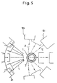
- the emitted region S of emitting beam L by a plurality (for example, 12 pieces) of emitters 21 - 32 is fixed to one place for the neck and finish portion 1 of a glass bottle 3 which rotates in an R direction at a fixed position, and the relevant emitting beams L are converged to the emitted region S from different directions.
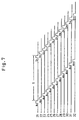
- emitters 21 - 32 are repeatedly switched instantaneously to the light emitting condition throughout 360 ° successively one by one in the lighting timing, for example, as shown in Fig. 7 while the glass bottle 3 is continuously rotated around the glass bottle center P in the check detection section D (see Fig. 4).
- the emitted region S is set to, for example, a rectangular form and the lateral width X (emitted width) of the emitted region S is set to 5 mm, the lighting timing is switched for every 1 mm pitch of the circumferential length.
- emitted width X is set to be greater than the circumferential length on which the glass bottle 3 rotates to move, emitting beams L can be emitted to the neck and finish portion 1 of the glass bottle 3 free of unemitted portions on the neck and finish portion 1 of the glass bottle 3 which passes the emitted region S.
- character Y designates the vertical length of the rectangular emitted region S.
- the first vertical check detection is carried out, for example, at the lighting timing clock a 1 - a 12 shown in Fig. 7 and the data is collected from this detection area for processing. Then, when the next detection area in the neck and finish portion 1 is superimposed on the emitted region S, the second vertical check detection is carried out at the lighting timing clock b 1 - b 12 , and the data is collected from this detection area for processing. Thereafter, in the similar manner, the data is collected and processed throughout one circumference of the neck and finish portion 1 of the glass bottle 3.
- numerals 51 through 58 designate a plurality of light receivers (cameras).
- this invention is configured to delete the data taken in as reflected lights reflected at the seam and the data taken in as direct lights transmitting the neck and finish portion, the above-mentioned inconvenience can be positively solved and this also enables accurate vertical check detection.
- each of the light receiving sensor 2 which receivers 51 - 58 possess is configured with diode arrays comprising a plurality of light-receiving elements 11 - 18 divided in advance in such a manner to correspond to the vertical position of the neck and finish portion, even the contents of the check can be identified and detected.
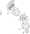
- the reflected light A totally reflected at the upper vertical check a is received, for example, by a light receiving element 18 and the reflected light B totally reflected at the middle vertical check b is received at a light receiving element 14, and the reflected light C totally reflected at the lower vertical check c is received at a light receiving element 11. Consequently, the upper vertical check a, middle vertical check b, and lower vertical check c can be identified and detected.
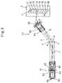
- 12 pieces of emitters 21 - 32 used in this invention are configured, respectively, as an emitter 31 indicated in Fig. 2, by installing a plurality of light emitting diodes (LED) 60, a converging lens system 61 containing a condenser lens, and a slit 62 intermediately installed to the lens system 61 in a pair of separable cylindrical boxes 63, 63.
- LED light emitting diodes
- the diode array cameras 51 - 58 comprise a light receiving sensor 2 comprising a diode array composed of a plurality of light receiving elements 11 - 18, a cylindrical box 66 with a hole 65 for allowing reflected lights A, B, C, to pass, and a light converging lens system 64, respectively.
- This light converging lens system 64 is installed in the box 66 in such a manner that the system receives the reflected lights A, B, C and the reflected light A is received by the light receiving element 18, the reflected light B by the light receiving element 14, and further the reflected light C by the light receiving element 11.
- each light receiving sensor 2 is composed with divided light receiving elements 11 - 18 in this invention, the noise region can be made smaller. Consequently, the differentiation processing of the data corresponding to the detection signal taken in by the receiver as in the case of conventional check detectors is no longer required.
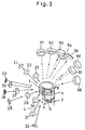
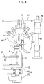
- Fig. 1 and Fig. 2 are illustrations for optical principle used for carrying out detection of presence of, for example, upper vertical check a, middle vertical check b, lower vertical check c, etc., while Fig. 3 through Fig. 6 show the details of the check detector.
- a glass bottle 3 taken out successively from a conveyor by an infeed wheel not illustrated is intermittently transferred by a main star wheel 33 and conveyed successively to a check detection section D.
- the detected glass bottle 3 is returned to a conveyor 1 via a take-out wheel by the star wheel 33.
- the star wheel 33 is equipped with a rotating shaft to which two wheel plates 34 with glass bottle introducing sections formed on the circumference are mounted at suitable intervals.
- Numeral 35 is a glass bottle rotating means comprising a turntable 36 and a motor 37 and is mounted to a check detection section D.
- the star wheel 33 is configured to intermittently stop the drive every time the glass bottle introducing section is located at a position that corresponds to the turntable 36, and is configured to rotate the glass bottle 2 around the glass bottle center P at a fixed position while the star wheel 33 makes an intermittent drive stop.
- Numeral 38 is a check detector of the neck and finish portion 1 of the glass bottle 3 arranged at the check detection section D, comprising a post 40 equipped with an elevating member 39 which is tree to change the position and free to be fixed in the vertical direction and erectly mounted to the outside of the glass bottle handling route by the star wheel 33, a horizontal guide 41 extendedly equipped to the elevating member 39 in the condition to allow it to cross the glass bottle handling route, a slide block 42 equipped along the horizontal guide 41 in such a manner as to be free to change the position and free to be fixed, and a plurality of emitters 21 - 32 configured as described above and receivers 51 - 58 which function as diode array cameras as described above, both mounted to the slide blocks 42, respectively.
- emitters 21 - 32 and receivers 51 - 58 are arranged face to face so that vertical checks a, b, c can be easily detected.
- the most popular simple threaded type for pilfer-proof cap is employed as shown in Fig. 8.
- an emitter bracket 43 is mounted, respectively, on one side of the glass bottle handling route in the width direction with a specified angle provided with respect to the slide block 42, and at the same time, emitters 21 - 32 are mounted to each bracket 43 so that emitting light L can be emitted from obliquely above, from obliquely below, and from the horizontal direction to the outside of the neck and finish portion 1 of the glass bottle 3 rotated at the fixed position, and the emitting light L by a plurality of the emitters 21 - 32 is converged to the emitted region S which is superimposed on the neck and finish portion 1.
- the light emitting direction of two emitters 28, 32 is directed obliquely above, that of the two emitters 26, 31 directed nearly to horizontal direction, and that of the remaining emitters directed obliquely below.
- receivers 51 - 58 are mounted on the other side of the glass bottle handling route in the width direction with respect to the slide block 42.
- the receiver bracket 44 is mounted, respectively, with the specified angle provided, and at the same time, receivers 51 - 58 are mounted to each bracket 44 so that the reflected light reflected at the neck and finish portion 1 can be detected.
- the receivers 51 - 58 are mounted to each bracket 44 independently or in a pair.
- Numeral 45 is a means for detecting the presence of checks of the neck and finish portion 1, and detects the presence of upper vertical check a, middle vertical check b, and lower vertical check c at the neck and finish portion 1 based on the quantity of light caught by receivers 51 - 58.
- Numeral 46 is an emitter control section for switching emitters 21 - 32 successively one by one to the repeated emitting condition.
- Numeral 47 is a receiver control section and constantly operates all the receivers 51 - 58 in the emitting condition so that the reflected lights A, B, C reflected at the vertical checks a, b, c are inputted as data D 1 if any of the above-mentioned vertical checks a, b, c is generated. Consequently, reflected light reflected at the mold seam formed at the neck and finish portion 1 and direct light transmitting the neck and finish portion 1 are inputted also as data D 2 , D 3 , respectively.
- mask data M is created in advance for deleting the two types of data D 2 , D 3 , respectively. And masking operation is carried out by superimposing the mask data M on the inputted data D 1 , D 2 , D 3 by combinations of emitters 21 - 32 with receivers 51 - 58 which appear on one screen of the detection monitor during operation of the check detector 38 so that the check presence detecting means does not process the glass bottle as defective with the reflected light from the seam.
- a non-defective glass bottle which has no check at the neck and finish portion 1 and has a seeds, blister at the seam that causes no problem as a product is set to the check detector 38, and the inspected portions with the worst condition of the relevant glass bottle are emitted successively with the emitting light, and in such event, combinations of emitters and receivers subject to the reflected light are looked over, and which combinations of receivers react with the seam is confirmed.
- which combination of receivers react with direct light is also confirmed and the mask data M is created.
- the two types of data D 2 , D 3 can be deleted by the masking operation from the detection monitor screen.
- the invention has an advantage to shorten the data transfer time not only as light receiving sensor used in the conventional art but also as light receiving sensor as compared to CCD which carries out data processing by 1 bit.
- emitting light L from emitters 21 - 32 is directed to the outer surface of the neck and finish portion and the emitting light L is converged to one place S from a plurality of directions which differ one another, and the neck and finish portion 1 that corresponds to the 1 mm pitch of circumferential length that transmitting the one position S is continuously emitted with emitting light L successively one by one from emitter 21 to emitter 32, and to prevent any blank of light emission, the following neck and finish portion 1 which corresponds to 1 mm pitch of circumferential length is continuously emitted with emitting light L one by one from emitter 21 to emitter 32 while the neck and finish portion passes the one place S, and this operation is repeatedly carried out for 360° .
- the light emitting direction of emitting light L from emitters 21 - 32 is directed to the outer surface of the neck and finish portion and the emitting light L is converged to one place S, but the invention is able to be embodied by directing the light emitting direction of emitting light L to the vicinity of the inner surface of the neck and finish portion.
- emitters and receivers may be arranged as required in accord with the types of checks. In the above-mentioned embodiment, vertical checks are detected, but in this invention, checks other than vertical checks can be optionally detected by varying the setting patterns.
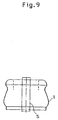
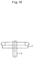
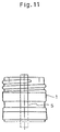
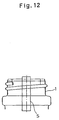
- Fig. 9 shows a crown cap neck, Fig. 10 a lip neck, Fig. 11 a deep neck for pilfer proof caps, Fig. 12 a stopper neck, and Fig. 13 a cork neck, respectively.
- character S designates a rectangular emitted region as described above.
- numeral 70 designates a camera proper and creates detection data D based on the data D 1 , D 2 , D 3 detected by 8 pieces of light receivers 51 - 58.
- Numeral 90 designates a data processor and sorts all the detection data D at the stage where the detection data D is summarized. And during detection, the camera proper 70 only operates. After completion of detection, all the detection data D is absorbed into the data processor 90 and stored in memory. The detection data D is outputted to the data processor 90 from the camera proper 70 via the detection data line L 1 as 8-bit data. And at the data processor 90, acceptance or rejection of the glass bottle neck and finish portion 1 is performed, and the results are displayed on the detection monitor screen of the personal computer 91.
- checks are filed in advance by types. For example, the column of presence of upper vertical check a, middle vertical check b, and lower vertical check c generated at the upper, middle, and lower positions of the glass bottle neck and finish portion 1 in that order are displayed on the detection monitor screen by calling the file for vertical checks.
- Collation of the detection data D sent from the personal computer 91 to the controller 90a with the mask data M created in advance in accord with the types of glass bottle 3 of the inspected subject is carried out by the masking operation from the detection monitor screen.
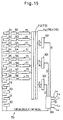
- Fig. 15 shows the overall configuration of the camera proper 70.
- the 8 light receivers 51 - 58 (camera 1 - camera 8) as a diode array camera which is one of the composing elements of the camera proper 70, for example, a delivery route of the data caught by the light receiving sensor 2 mounted at, for example, the receiver 53 is shown.
- numeral 69 is a signal line of the light receiving element 11.
- the light receiving element 11 is one of the eight light receiving elements 11 - 18 composing the light receiving sensor 2 of the light receiver 53.
- PRE AMP 8 channels
- analog-system signal processing mechanism for example, high pass filter (8 channels) 72, low pass filter (8 channels) 73, comparators 74, 75, 76] are equipped. If any of vertical checks a, b, c is generated in the neck and finish portion 1, current output (data signal) D 1 in proportion to the reflected lights A, B, C reflected at vertical checks a, b, c is outputted to the signal line 69.
- the data signals D 1 , D 2 , D 3 (hereinafter called simply the "detection data") passing the high pass filter 72 and the low pass filter 73 are sent out to three comparators 74, 75, 76, respectively, in one set.
- non-defective signal blue signal
- X 1 which corresponds to detection data
- defective signal yellow signal
- defective signal (red signal) Z 1 (which corresponds to the detection data) subject to reflected light with stronger light quantity than that of the defective signal Y 1 is sent out to the main memory section 82 when the signals are temporarily stored in memory at the pre-memory section 81 and collected.
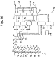
- the pre-memory sections 77, 79, 81 are to temporarily store the first detection data by turning on timing clocks a 1 - a 12 from the emitters 21 - 32 until the second detection is carried out by turning on timing clocks b 1 - b 12 from the emitters 21 - 32 shown in Fig. 15. Thereafter, the neck and finish portion 1 of the glass bottle 3 is continuously emitted with emitting light L with care to eliminate no unemitted portion in the neck and finish portion 1 of the glass bottle 3 passing the emitted region S, and the third detection data by emitters 21 - 32, fourth detection data ... are temporarily stored successively in pre-memory portions 77, 79, 81.
- the detection data shall be collected throughout at least one circumference of the neck and finish portion 1 of the glass bottle 3.
- numeral 101 is a logic circuit.
- detection data (X 1 , Y 1 , Z 1 , X 2 , Y 2 , Z 2 , ⁇ X 64 , Y 64 , Z 64 ) of 8 (number of receivers) ⁇ 8 (number of light receiving element) ⁇ 3 (number of comparators) are temporarily stored in the pre-memory sections 77, 79, 81, and thereafter, the detection data in a lump is stored in the main memory sections 78, 80, 82.
- timing clock b 2 comes from the emitter 22
- 8 ⁇ 8 ⁇ 3 pieces of data are temporarily stored in a lump at locations with different addresses of the pre-memory portion 77, 79, and 81. This operation is carried out up to the twelfth emitter 32 and the second detection by turning on timing clocks b 1 - b 12 is completely finished.
- the detection data of 64 ⁇ 12 (number of emitters) ⁇ 3 (number of comparators) obtained by the second detection is collated with the first detection data by turning on timing clocks a 1 - a 12 in main memory sections 78, 80, 82, and both detection data are totaled and stored in memory.
- the main memory sections 78, 80, 82 are constructed with OR circuits.
- the third detection data is collated with the first and the second detection data at the main memory sections 78, 80, 82. And by totaling the first detection date and, the second detection date, the third detection data is also stored in memory at the main memory section 78, 80, 82. Thereafter, in the similar operation, the data is collected and processed throughout the one circumference of the neck portion 1 of the glass bottle 3.
- numeral 93 designates a control signal bus and is equipped between the main logic circuit 94 and main memory sections 78, 80, 82.In this control signal bus 93, a request for read/write control data is made to the main memory sections 78, 80, 82. And between the main logic circuit 94 and the microcomputer (see Fig. 14) 92, a logic control signal line L 2 is equipped.
- Numeral 95 designates a data bus, 96 an address bus, 99 a DA converter, and 98 a light emitter driver driven by the driving means 97, and the power of the turning on timing clocks a 1 - a 12 , b 1 - b 12 ...
- character L 3 designates a reference clock line
- character L 4 designates a set data line of the detection condition
- character L 5 designates a gate
- character L 6 designates a line for confirming presence of a glass bottle at the time of detection.
- a plurality of emitters and a plurality of receivers are arranged in accord with the types of checks generated in the neck and finish portion of the glass bottle, but since each of the light receiving sensors of receivers is composed with diode arrays comprising a plurality of light receiving elements divided in advance to correspond to the vertical position of the neck and finish portion while allowing the emitting light by a plurality of emitters to be converged to one emitted region, even the contents of the check can be identified and detected at many places at a stretch at one position.
Landscapes
- Physics & Mathematics (AREA)
- Health & Medical Sciences (AREA)
- Life Sciences & Earth Sciences (AREA)
- Chemical & Material Sciences (AREA)
- Analytical Chemistry (AREA)
- Biochemistry (AREA)
- General Health & Medical Sciences (AREA)
- General Physics & Mathematics (AREA)
- Immunology (AREA)
- Pathology (AREA)
- Investigating Materials By The Use Of Optical Means Adapted For Particular Applications (AREA)
- Sorting Of Articles (AREA)
Applications Claiming Priority (2)
| Application Number | Priority Date | Filing Date | Title |
|---|---|---|---|
| JP13117698A JP3908858B2 (ja) | 1998-03-31 | 1998-04-25 | ガラス壜口部のびり検査装置 |
| JP13117698 | 1998-04-25 |
Publications (3)
| Publication Number | Publication Date |
|---|---|
| EP0952443A1 true EP0952443A1 (de) | 1999-10-27 |
| EP0952443B1 EP0952443B1 (de) | 2012-07-25 |
| EP0952443B2 EP0952443B2 (de) | 2015-12-16 |
Family
ID=15051793
Family Applications (1)
| Application Number | Title | Priority Date | Filing Date |
|---|---|---|---|
| EP99108092.0A Expired - Lifetime EP0952443B2 (de) | 1998-04-25 | 1999-04-23 | Vorrichtung zum Detektieren von Fehlern im Hals- und Endbereich einer geformten Flasche |
Country Status (2)
| Country | Link |
|---|---|
| US (1) | US6275287B1 (de) |
| EP (1) | EP0952443B2 (de) |
Cited By (16)
| Publication number | Priority date | Publication date | Assignee | Title |
|---|---|---|---|---|
| EP1106993A2 (de) | 1999-12-02 | 2001-06-13 | Owens-Brockway Glass Container Inc. | Nachweis von Rissen im Halsendteil von Glasbehältern |
| WO2001055705A1 (fr) * | 2000-01-31 | 2001-08-02 | Dmo Consulting S.A. | Installation et procede pour la detection de glacures |
| FR2846422A1 (fr) * | 2002-10-25 | 2004-04-30 | Sgcc | Dispositif d'eclairage d'un article pour la detection automatique de defauts et installation de detection automatique de defauts comportant un tel dispositif |
| EP1346205B1 (de) * | 2000-12-29 | 2007-04-25 | Krones Ag | Verfahren und vorrichtung zur optischen inspektion von flaschen |
| EP1560017A4 (de) * | 2002-10-18 | 2007-12-19 | Kirin Techno System Corp | Prüfvorrichtung für glasflaschen |
| EP2016397A1 (de) * | 2006-05-10 | 2009-01-21 | Saverglass SAS | Vorrichtung und verfahren zum nachweis eines defekts bei einem abschlussring eines glases |
| EP2434276A1 (de) * | 2010-09-24 | 2012-03-28 | Symplex Vision System GmbH | Inspektionsverfahren, Inspektionsstation und Belichtungs- und Auswertevorrichtung |
| CN102667453A (zh) * | 2009-12-22 | 2012-09-12 | 环宇制罐株式会社 | 罐的凹凸检测装置 |
| DE202013104938U1 (de) | 2013-11-05 | 2015-02-06 | Krones Ag | Vorrichtung zur optischen Inspektion eines Mündungsbereichs eines Behälters |
| EP2623962A4 (de) * | 2010-10-01 | 2017-05-03 | Kirin Techno-System Company, Limited | Prüfsystem und -verfahren für glasflaschen |
| CN108132259A (zh) * | 2018-01-26 | 2018-06-08 | 康耀电子科技有限公司 | 一种转盘式受片检测装置的应用方法 |
| US10000405B2 (en) | 2010-06-29 | 2018-06-19 | Owens-Brockway Glass Container Inc. | Stelvin/cork glass wine bottles |
| CN110431405A (zh) * | 2017-02-06 | 2019-11-08 | 东洋玻璃株式会社 | 玻璃瓶的检查装置 |
| CN112763462A (zh) * | 2020-12-31 | 2021-05-07 | 宋凯 | 一种基板玻璃透光率检测设备及基板玻璃制备工艺 |
| CN114590990A (zh) * | 2022-02-21 | 2022-06-07 | 甘肃旭康材料科技有限公司 | 瓶口尺寸调节系统和瓶口尺寸调节方法 |
| EP4242642A1 (de) * | 2022-03-09 | 2023-09-13 | Analitica d.o.o. | Behälteruntersuchungsvorrichtung |
Families Citing this family (22)
| Publication number | Priority date | Publication date | Assignee | Title |
|---|---|---|---|---|
| JP2001344592A (ja) * | 2000-05-31 | 2001-12-14 | Toyo Jidoki Co Ltd | キャップ取付け状態検査方法 |
| US6512239B1 (en) * | 2000-06-27 | 2003-01-28 | Photon Dynamics Canada Inc. | Stereo vision inspection system for transparent media |
| NO315264B1 (no) * | 2001-01-23 | 2003-08-11 | Tomra Systems Asa | Deteksjonssystem |
| EP1270433B1 (de) * | 2001-06-20 | 2011-02-23 | Japan Crown Cork Co. Ltd. | Verfahren zur Prüfung eines auf einer Flasche angebrachtem Verschlusses und Vorrichtung |
| US6903814B1 (en) | 2003-03-05 | 2005-06-07 | Owens-Brockway Glass Container Inc. | Container sealing surface inspection |
| US7060999B2 (en) | 2004-07-09 | 2006-06-13 | Owens-Brockway Glass Container Inc. | Apparatus and method for inspecting ribbed containers |
| US7876951B2 (en) * | 2006-10-23 | 2011-01-25 | Emhart Glass S. A. | Machine for inspecting glass containers |
| US7626158B2 (en) * | 2006-10-23 | 2009-12-01 | Emhart Glass S.A. | Machine for inspecting glass containers |
| US7816639B2 (en) * | 2006-10-23 | 2010-10-19 | Emhart Glass S.A. | Machine for inspecting glass containers at an inspection station using an addition of a plurality of illuminations of reflected light |
| US7688437B2 (en) | 2007-05-02 | 2010-03-30 | Emhart Glass S.A. | Machine for inspecting glass containers |
| US7697132B2 (en) | 2007-05-02 | 2010-04-13 | Emhart Glass S.A. | Machine for inspecting glass containers |
| US8135206B2 (en) | 2007-05-02 | 2012-03-13 | Emhart Glass S.A. | Machine for inspecting glass containers |
| US9314748B1 (en) * | 2012-06-08 | 2016-04-19 | Mark Maclean-Blevins | System and method for dispensing and aeration of a beverage |
| DE102012022474B4 (de) * | 2012-11-19 | 2014-06-26 | Khs Corpoplast Gmbh | Inspektionsanordnung für Behältermündungen |
| US8941825B2 (en) | 2013-03-15 | 2015-01-27 | Owens-Brockway Glass Container Inc. | Container inspection |
| US10012598B2 (en) | 2015-07-17 | 2018-07-03 | Emhart S.A. | Multi-wavelength laser check detection tool |
| CN110044293B (zh) * | 2018-01-17 | 2020-11-17 | 深圳中科飞测科技有限公司 | 一种三维重构系统及三维重构方法 |
| MA52168A (fr) * | 2018-03-30 | 2021-02-17 | Amgen Inc | Inspection de récipient à médicament à base d'appareil de prise de vues |
| EP3968012A1 (de) * | 2020-09-11 | 2022-03-16 | Schott Ag | Vorrichtung zur inspektion eines kreisförmigen länglichen elements |
| CN113477550B (zh) * | 2021-08-24 | 2024-11-22 | 安徽顺鼎阿泰克科技有限公司 | 玻璃瓶喷涂线入料位检测方法及装置 |
| CN114062378B (zh) * | 2021-10-28 | 2024-06-11 | 山东科技大学 | 一种直线式随动瓶口裂纹检测系统 |
| CN118904734B (zh) * | 2024-09-29 | 2025-02-18 | 山东明佳科技有限公司 | 一种自适应混产瓶口检测方法 |
Citations (6)
| Publication number | Priority date | Publication date | Assignee | Title |
|---|---|---|---|---|
| US4293219A (en) * | 1977-08-24 | 1981-10-06 | Societe Generale Pour L'emballage | Method and apparatus for inspecting transparent objects |
| GB2087549A (en) * | 1980-11-10 | 1982-05-26 | Barry Wehmiller Co | A method of and apparatus for compensating signal drift during container inspection |
| US4650326A (en) * | 1983-06-21 | 1987-03-17 | Mitsubishi Denki Kabushiki Kaisha | Apparatus for inspecting bottles |
| EP0222959A1 (de) * | 1985-11-15 | 1987-05-27 | Peter Dr. Hermann | Vorrichtung zur Erkennung von Fehlern, insbesondere Rissen, in transparenten Körpern auf optischem Wege |
| US4701612A (en) * | 1985-07-19 | 1987-10-20 | Owens-Illinois, Inc. | Inspection of container finish |
| EP0763727A1 (de) * | 1995-09-13 | 1997-03-19 | Precision Co., Ltd. | Vorrichtung zum Detektieren von Fehlern in Hals- und Fertigteile einer geformten Flasche |
Family Cites Families (5)
| Publication number | Priority date | Publication date | Assignee | Title |
|---|---|---|---|---|
| CH652826A5 (de) † | 1980-06-16 | 1985-11-29 | Peter Dr Hermann | Vorrichtung zur erkennung von fehlern, insbesondere risse, in transparenten koerpern auf optischem wege. |
| DE9101934U1 (de) † | 1990-03-27 | 1991-05-08 | Fa. Hermann Heye, 3063 Obernkirchen | Fotodetektor zur Fehlerprüfung von Glasbehältern |
| DE9003522U1 (de) † | 1990-03-27 | 1991-01-03 | Fa. Hermann Heye, 3063 Obernkirchen | Fotodetektor zur Fehlerprüfung von Glasbehältern |
| JP2759231B2 (ja) | 1991-03-22 | 1998-05-28 | 山村硝子株式会社 | ガラス壜口部の欠陥検査装置 |
| DE29504073U1 (de) † | 1995-03-10 | 1995-05-04 | Fa. Hermann Heye, 31683 Obernkirchen | Vorrichtung zur Prüfung auf Licht reflektierende Fehler |
-
1999
- 1999-04-21 US US09/295,703 patent/US6275287B1/en not_active Expired - Lifetime
- 1999-04-23 EP EP99108092.0A patent/EP0952443B2/de not_active Expired - Lifetime
Patent Citations (6)
| Publication number | Priority date | Publication date | Assignee | Title |
|---|---|---|---|---|
| US4293219A (en) * | 1977-08-24 | 1981-10-06 | Societe Generale Pour L'emballage | Method and apparatus for inspecting transparent objects |
| GB2087549A (en) * | 1980-11-10 | 1982-05-26 | Barry Wehmiller Co | A method of and apparatus for compensating signal drift during container inspection |
| US4650326A (en) * | 1983-06-21 | 1987-03-17 | Mitsubishi Denki Kabushiki Kaisha | Apparatus for inspecting bottles |
| US4701612A (en) * | 1985-07-19 | 1987-10-20 | Owens-Illinois, Inc. | Inspection of container finish |
| EP0222959A1 (de) * | 1985-11-15 | 1987-05-27 | Peter Dr. Hermann | Vorrichtung zur Erkennung von Fehlern, insbesondere Rissen, in transparenten Körpern auf optischem Wege |
| EP0763727A1 (de) * | 1995-09-13 | 1997-03-19 | Precision Co., Ltd. | Vorrichtung zum Detektieren von Fehlern in Hals- und Fertigteile einer geformten Flasche |
Cited By (25)
| Publication number | Priority date | Publication date | Assignee | Title |
|---|---|---|---|---|
| EP1106993A2 (de) | 1999-12-02 | 2001-06-13 | Owens-Brockway Glass Container Inc. | Nachweis von Rissen im Halsendteil von Glasbehältern |
| EP1106993A3 (de) * | 1999-12-02 | 2001-11-14 | Owens-Brockway Glass Container Inc. | Nachweis von Rissen im Halsendteil von Glasbehältern |
| RU2253104C2 (ru) * | 1999-12-02 | 2005-05-27 | Оуэнс-Броквэй Гласс Контейнер Инк. | Детектирование посечки горлышка посудной тары |
| EP2267437A1 (de) | 1999-12-02 | 2010-12-29 | Owens-Brockway Glass Container Inc. | Nachweis von Rissen in Glassbehältern Halsendteil |
| WO2001055705A1 (fr) * | 2000-01-31 | 2001-08-02 | Dmo Consulting S.A. | Installation et procede pour la detection de glacures |
| EP1346205B1 (de) * | 2000-12-29 | 2007-04-25 | Krones Ag | Verfahren und vorrichtung zur optischen inspektion von flaschen |
| EP1560017A4 (de) * | 2002-10-18 | 2007-12-19 | Kirin Techno System Corp | Prüfvorrichtung für glasflaschen |
| US7329855B2 (en) | 2002-10-18 | 2008-02-12 | Kirin Techno-System Corporation | Optical inspection of glass bottles using multiple cameras |
| FR2846422A1 (fr) * | 2002-10-25 | 2004-04-30 | Sgcc | Dispositif d'eclairage d'un article pour la detection automatique de defauts et installation de detection automatique de defauts comportant un tel dispositif |
| WO2004040279A1 (fr) | 2002-10-25 | 2004-05-13 | S.G.C.C. | Dispositif d'éclairage d'un article pour la détection automatique de défauts et installation de détection automatique de défauts comportant un tel dispositif |
| EP2016397A1 (de) * | 2006-05-10 | 2009-01-21 | Saverglass SAS | Vorrichtung und verfahren zum nachweis eines defekts bei einem abschlussring eines glases |
| CN102667453A (zh) * | 2009-12-22 | 2012-09-12 | 环宇制罐株式会社 | 罐的凹凸检测装置 |
| CN102667453B (zh) * | 2009-12-22 | 2014-06-11 | 环宇制罐株式会社 | 罐的凹凸检测装置 |
| US8786865B2 (en) | 2009-12-22 | 2014-07-22 | Universal Can Corporation | Asperity detection device for can |
| US10000405B2 (en) | 2010-06-29 | 2018-06-19 | Owens-Brockway Glass Container Inc. | Stelvin/cork glass wine bottles |
| EP2434276A1 (de) * | 2010-09-24 | 2012-03-28 | Symplex Vision System GmbH | Inspektionsverfahren, Inspektionsstation und Belichtungs- und Auswertevorrichtung |
| EP2623962A4 (de) * | 2010-10-01 | 2017-05-03 | Kirin Techno-System Company, Limited | Prüfsystem und -verfahren für glasflaschen |
| DE202013104938U1 (de) | 2013-11-05 | 2015-02-06 | Krones Ag | Vorrichtung zur optischen Inspektion eines Mündungsbereichs eines Behälters |
| CN110431405A (zh) * | 2017-02-06 | 2019-11-08 | 东洋玻璃株式会社 | 玻璃瓶的检查装置 |
| CN108132259A (zh) * | 2018-01-26 | 2018-06-08 | 康耀电子科技有限公司 | 一种转盘式受片检测装置的应用方法 |
| CN108132259B (zh) * | 2018-01-26 | 2023-06-16 | 康耀电子科技有限公司 | 一种转盘式受片检测装置的应用方法 |
| CN112763462A (zh) * | 2020-12-31 | 2021-05-07 | 宋凯 | 一种基板玻璃透光率检测设备及基板玻璃制备工艺 |
| CN114590990A (zh) * | 2022-02-21 | 2022-06-07 | 甘肃旭康材料科技有限公司 | 瓶口尺寸调节系统和瓶口尺寸调节方法 |
| CN114590990B (zh) * | 2022-02-21 | 2023-11-28 | 甘肃旭康材料科技有限公司 | 瓶口尺寸调节系统和瓶口尺寸调节方法 |
| EP4242642A1 (de) * | 2022-03-09 | 2023-09-13 | Analitica d.o.o. | Behälteruntersuchungsvorrichtung |
Also Published As
| Publication number | Publication date |
|---|---|
| EP0952443B1 (de) | 2012-07-25 |
| US6275287B1 (en) | 2001-08-14 |
| EP0952443B2 (de) | 2015-12-16 |
Similar Documents
| Publication | Publication Date | Title |
|---|---|---|
| EP0952443B1 (de) | Vorrichtung zum Detektieren von Fehlern im Hals- und Endbereich einer geformten Flasche | |
| US4959537A (en) | Method and apparatus for inspecting transparent containers | |
| US5200801A (en) | Inspection of container finish | |
| EP1560017B1 (de) | Prüfvorrichtung für glasflaschen | |
| EP0957355B1 (de) | Optische Inspektion von durchsichtigen Behältern mit Nutzung zweier Kameras und einer einzelnen Lichtquelle | |
| EP0961113B1 (de) | Inspektion von Behältern unter Verwendung nur einer flächenhaften Sensormatrix und abwechselnd gepulsten Lichtquellen | |
| US4280624A (en) | Bottle inspection apparatus | |
| US4584469A (en) | Optical detection of radial reflective defects | |
| US4701612A (en) | Inspection of container finish | |
| US5499718A (en) | System and method for seeking and presenting an area for reading with a vision system | |
| US6473169B1 (en) | Integrated leak and vision inspection system | |
| US4736851A (en) | Process and apparatus for the automatic inspection by transparency contrast in particular of containers | |
| US4958223A (en) | Inspection of container finish | |
| EP1560018B1 (de) | Verfahren und vorrichtung zur herstellung eines referenzbildes bei einer prüfvorrichtung für glasflaschen | |
| JP3908858B2 (ja) | ガラス壜口部のびり検査装置 | |
| EP0337421A2 (de) | Verfahren und Vorrichtung zur Prüfung der Seitenwand einer Flasche | |
| US8058607B2 (en) | Machine for inspecting glass containers at an inspection station using an addition of a plurality of illuminations of reflected light | |
| US4775889A (en) | Bottle mouth defect inspection apparatus | |
| EP0763727B1 (de) | Vorrichtung zum Detektieren von Fehlern in Hals- und Fertigteile einer geformten Flasche | |
| US4424441A (en) | Method and apparatus for inspecting glass containers | |
| US20080094618A1 (en) | Machine for inspecting glass containers | |
| US5214713A (en) | Container inspection system with systolic array processing | |
| JPH01250845A (ja) | チップ状部品の自動外観検査機 | |
| AU622587B2 (en) | Inspection of container finish | |
| PH26987A (en) | Inspection of container finish |
Legal Events
| Date | Code | Title | Description |
|---|---|---|---|
| PUAI | Public reference made under article 153(3) epc to a published international application that has entered the european phase |
Free format text: ORIGINAL CODE: 0009012 |
|
| AK | Designated contracting states |
Kind code of ref document: A1 Designated state(s): DE FR GB IT |
|
| AX | Request for extension of the european patent |
Free format text: AL;LT;LV;MK;RO;SI |
|
| 17P | Request for examination filed |
Effective date: 19991217 |
|
| AKX | Designation fees paid |
Free format text: DE FR GB IT |
|
| 17Q | First examination report despatched |
Effective date: 20060905 |
|
| GRAP | Despatch of communication of intention to grant a patent |
Free format text: ORIGINAL CODE: EPIDOSNIGR1 |
|
| GRAS | Grant fee paid |
Free format text: ORIGINAL CODE: EPIDOSNIGR3 |
|
| GRAA | (expected) grant |
Free format text: ORIGINAL CODE: 0009210 |
|
| AK | Designated contracting states |
Kind code of ref document: B1 Designated state(s): DE FR GB IT |
|
| REG | Reference to a national code |
Ref country code: GB Ref legal event code: FG4D |
|
| REG | Reference to a national code |
Ref country code: DE Ref legal event code: R096 Ref document number: 69944308 Country of ref document: DE Effective date: 20120920 |
|
| PLBI | Opposition filed |
Free format text: ORIGINAL CODE: 0009260 |
|
| 26 | Opposition filed |
Opponent name: HEYE INTERNATIONAL GMBH Effective date: 20130423 |
|
| PG25 | Lapsed in a contracting state [announced via postgrant information from national office to epo] |
Ref country code: IT Free format text: LAPSE BECAUSE OF FAILURE TO SUBMIT A TRANSLATION OF THE DESCRIPTION OR TO PAY THE FEE WITHIN THE PRESCRIBED TIME-LIMIT Effective date: 20120725 |
|
| PLAX | Notice of opposition and request to file observation + time limit sent |
Free format text: ORIGINAL CODE: EPIDOSNOBS2 |
|
| REG | Reference to a national code |
Ref country code: DE Ref legal event code: R026 Ref document number: 69944308 Country of ref document: DE Effective date: 20130423 |
|
| PLAF | Information modified related to communication of a notice of opposition and request to file observations + time limit |
Free format text: ORIGINAL CODE: EPIDOSCOBS2 |
|
| PLBB | Reply of patent proprietor to notice(s) of opposition received |
Free format text: ORIGINAL CODE: EPIDOSNOBS3 |
|
| GBPC | Gb: european patent ceased through non-payment of renewal fee |
Effective date: 20130423 |
|
| PG25 | Lapsed in a contracting state [announced via postgrant information from national office to epo] |
Ref country code: GB Free format text: LAPSE BECAUSE OF NON-PAYMENT OF DUE FEES Effective date: 20130423 |
|
| REG | Reference to a national code |
Ref country code: FR Ref legal event code: PLFP Year of fee payment: 17 |
|
| PUAH | Patent maintained in amended form |
Free format text: ORIGINAL CODE: 0009272 |
|
| STAA | Information on the status of an ep patent application or granted ep patent |
Free format text: STATUS: PATENT MAINTAINED AS AMENDED |
|
| 27A | Patent maintained in amended form |
Effective date: 20151216 |
|
| AK | Designated contracting states |
Kind code of ref document: B2 Designated state(s): DE FR GB IT |
|
| REG | Reference to a national code |
Ref country code: DE Ref legal event code: R102 Ref document number: 69944308 Country of ref document: DE |
|
| REG | Reference to a national code |
Ref country code: FR Ref legal event code: PLFP Year of fee payment: 18 |
|
| REG | Reference to a national code |
Ref country code: FR Ref legal event code: PLFP Year of fee payment: 19 |
|
| PGFP | Annual fee paid to national office [announced via postgrant information from national office to epo] |
Ref country code: DE Payment date: 20170425 Year of fee payment: 19 Ref country code: FR Payment date: 20170424 Year of fee payment: 19 |
|
| REG | Reference to a national code |
Ref country code: DE Ref legal event code: R119 Ref document number: 69944308 Country of ref document: DE |
|
| PG25 | Lapsed in a contracting state [announced via postgrant information from national office to epo] |
Ref country code: DE Free format text: LAPSE BECAUSE OF NON-PAYMENT OF DUE FEES Effective date: 20181101 |
|
| PG25 | Lapsed in a contracting state [announced via postgrant information from national office to epo] |
Ref country code: FR Free format text: LAPSE BECAUSE OF NON-PAYMENT OF DUE FEES Effective date: 20180430 |