EP0952460B1 - Vorrichtung zum Erkennen von Hindernissen für Kraftfahrzeuge - Google Patents
Vorrichtung zum Erkennen von Hindernissen für Kraftfahrzeuge Download PDFInfo
- Publication number
- EP0952460B1 EP0952460B1 EP99107302A EP99107302A EP0952460B1 EP 0952460 B1 EP0952460 B1 EP 0952460B1 EP 99107302 A EP99107302 A EP 99107302A EP 99107302 A EP99107302 A EP 99107302A EP 0952460 B1 EP0952460 B1 EP 0952460B1
- Authority
- EP
- European Patent Office
- Prior art keywords
- vehicle
- remote
- obstacle
- electromagnetic wave
- detection
- Prior art date
- Legal status (The legal status is an assumption and is not a legal conclusion. Google has not performed a legal analysis and makes no representation as to the accuracy of the status listed.)
- Expired - Lifetime
Links
- 238000001514 detection method Methods 0.000 title claims description 69
- 230000004044 response Effects 0.000 claims description 4
- 230000005540 biological transmission Effects 0.000 claims description 2
- 238000006243 chemical reaction Methods 0.000 description 3
- 238000010586 diagram Methods 0.000 description 2
- 230000009194 climbing Effects 0.000 description 1
- 238000004519 manufacturing process Methods 0.000 description 1
- 238000000034 method Methods 0.000 description 1
- 238000012544 monitoring process Methods 0.000 description 1
Images


Classifications
-
- G—PHYSICS
- G01—MEASURING; TESTING
- G01S—RADIO DIRECTION-FINDING; RADIO NAVIGATION; DETERMINING DISTANCE OR VELOCITY BY USE OF RADIO WAVES; LOCATING OR PRESENCE-DETECTING BY USE OF THE REFLECTION OR RERADIATION OF RADIO WAVES; ANALOGOUS ARRANGEMENTS USING OTHER WAVES
- G01S15/00—Systems using the reflection or reradiation of acoustic waves, e.g. sonar systems
- G01S15/88—Sonar systems specially adapted for specific applications
- G01S15/93—Sonar systems specially adapted for specific applications for anti-collision purposes
- G01S15/931—Sonar systems specially adapted for specific applications for anti-collision purposes of land vehicles
-
- G—PHYSICS
- G01—MEASURING; TESTING
- G01S—RADIO DIRECTION-FINDING; RADIO NAVIGATION; DETERMINING DISTANCE OR VELOCITY BY USE OF RADIO WAVES; LOCATING OR PRESENCE-DETECTING BY USE OF THE REFLECTION OR RERADIATION OF RADIO WAVES; ANALOGOUS ARRANGEMENTS USING OTHER WAVES
- G01S13/00—Systems using the reflection or reradiation of radio waves, e.g. radar systems; Analogous systems using reflection or reradiation of waves whose nature or wavelength is irrelevant or unspecified
- G01S13/86—Combinations of radar systems with non-radar systems, e.g. sonar, direction finder
- G01S13/862—Combination of radar systems with sonar systems
-
- G—PHYSICS
- G01—MEASURING; TESTING
- G01S—RADIO DIRECTION-FINDING; RADIO NAVIGATION; DETERMINING DISTANCE OR VELOCITY BY USE OF RADIO WAVES; LOCATING OR PRESENCE-DETECTING BY USE OF THE REFLECTION OR RERADIATION OF RADIO WAVES; ANALOGOUS ARRANGEMENTS USING OTHER WAVES
- G01S13/00—Systems using the reflection or reradiation of radio waves, e.g. radar systems; Analogous systems using reflection or reradiation of waves whose nature or wavelength is irrelevant or unspecified
- G01S13/88—Radar or analogous systems specially adapted for specific applications
- G01S13/93—Radar or analogous systems specially adapted for specific applications for anti-collision purposes
- G01S13/931—Radar or analogous systems specially adapted for specific applications for anti-collision purposes of land vehicles
-
- G—PHYSICS
- G01—MEASURING; TESTING
- G01S—RADIO DIRECTION-FINDING; RADIO NAVIGATION; DETERMINING DISTANCE OR VELOCITY BY USE OF RADIO WAVES; LOCATING OR PRESENCE-DETECTING BY USE OF THE REFLECTION OR RERADIATION OF RADIO WAVES; ANALOGOUS ARRANGEMENTS USING OTHER WAVES
- G01S13/00—Systems using the reflection or reradiation of radio waves, e.g. radar systems; Analogous systems using reflection or reradiation of waves whose nature or wavelength is irrelevant or unspecified
- G01S13/02—Systems using reflection of radio waves, e.g. primary radar systems; Analogous systems
- G01S13/06—Systems determining position data of a target
- G01S13/08—Systems for measuring distance only
- G01S13/32—Systems for measuring distance only using transmission of continuous waves, whether amplitude-, frequency-, or phase-modulated, or unmodulated
- G01S13/34—Systems for measuring distance only using transmission of continuous waves, whether amplitude-, frequency-, or phase-modulated, or unmodulated using transmission of continuous, frequency-modulated waves while heterodyning the received signal, or a signal derived therefrom, with a locally-generated signal related to the contemporaneously transmitted signal
-
- G—PHYSICS
- G01—MEASURING; TESTING
- G01S—RADIO DIRECTION-FINDING; RADIO NAVIGATION; DETERMINING DISTANCE OR VELOCITY BY USE OF RADIO WAVES; LOCATING OR PRESENCE-DETECTING BY USE OF THE REFLECTION OR RERADIATION OF RADIO WAVES; ANALOGOUS ARRANGEMENTS USING OTHER WAVES
- G01S15/00—Systems using the reflection or reradiation of acoustic waves, e.g. sonar systems
- G01S15/86—Combinations of sonar systems with lidar systems; Combinations of sonar systems with systems not using wave reflection
-
- G—PHYSICS
- G01—MEASURING; TESTING
- G01S—RADIO DIRECTION-FINDING; RADIO NAVIGATION; DETERMINING DISTANCE OR VELOCITY BY USE OF RADIO WAVES; LOCATING OR PRESENCE-DETECTING BY USE OF THE REFLECTION OR RERADIATION OF RADIO WAVES; ANALOGOUS ARRANGEMENTS USING OTHER WAVES
- G01S13/00—Systems using the reflection or reradiation of radio waves, e.g. radar systems; Analogous systems using reflection or reradiation of waves whose nature or wavelength is irrelevant or unspecified
- G01S13/88—Radar or analogous systems specially adapted for specific applications
- G01S13/93—Radar or analogous systems specially adapted for specific applications for anti-collision purposes
- G01S13/931—Radar or analogous systems specially adapted for specific applications for anti-collision purposes of land vehicles
- G01S2013/932—Radar or analogous systems specially adapted for specific applications for anti-collision purposes of land vehicles using own vehicle data, e.g. ground speed, steering wheel direction
-
- G—PHYSICS
- G01—MEASURING; TESTING
- G01S—RADIO DIRECTION-FINDING; RADIO NAVIGATION; DETERMINING DISTANCE OR VELOCITY BY USE OF RADIO WAVES; LOCATING OR PRESENCE-DETECTING BY USE OF THE REFLECTION OR RERADIATION OF RADIO WAVES; ANALOGOUS ARRANGEMENTS USING OTHER WAVES
- G01S13/00—Systems using the reflection or reradiation of radio waves, e.g. radar systems; Analogous systems using reflection or reradiation of waves whose nature or wavelength is irrelevant or unspecified
- G01S13/88—Radar or analogous systems specially adapted for specific applications
- G01S13/93—Radar or analogous systems specially adapted for specific applications for anti-collision purposes
- G01S13/931—Radar or analogous systems specially adapted for specific applications for anti-collision purposes of land vehicles
- G01S2013/9324—Alternative operation using ultrasonic waves
-
- G—PHYSICS
- G01—MEASURING; TESTING
- G01S—RADIO DIRECTION-FINDING; RADIO NAVIGATION; DETERMINING DISTANCE OR VELOCITY BY USE OF RADIO WAVES; LOCATING OR PRESENCE-DETECTING BY USE OF THE REFLECTION OR RERADIATION OF RADIO WAVES; ANALOGOUS ARRANGEMENTS USING OTHER WAVES
- G01S13/00—Systems using the reflection or reradiation of radio waves, e.g. radar systems; Analogous systems using reflection or reradiation of waves whose nature or wavelength is irrelevant or unspecified
- G01S13/88—Radar or analogous systems specially adapted for specific applications
- G01S13/93—Radar or analogous systems specially adapted for specific applications for anti-collision purposes
- G01S13/931—Radar or analogous systems specially adapted for specific applications for anti-collision purposes of land vehicles
- G01S2013/9327—Sensor installation details
- G01S2013/93271—Sensor installation details in the front of the vehicles
-
- G—PHYSICS
- G01—MEASURING; TESTING
- G01S—RADIO DIRECTION-FINDING; RADIO NAVIGATION; DETERMINING DISTANCE OR VELOCITY BY USE OF RADIO WAVES; LOCATING OR PRESENCE-DETECTING BY USE OF THE REFLECTION OR RERADIATION OF RADIO WAVES; ANALOGOUS ARRANGEMENTS USING OTHER WAVES
- G01S13/00—Systems using the reflection or reradiation of radio waves, e.g. radar systems; Analogous systems using reflection or reradiation of waves whose nature or wavelength is irrelevant or unspecified
- G01S13/88—Radar or analogous systems specially adapted for specific applications
- G01S13/93—Radar or analogous systems specially adapted for specific applications for anti-collision purposes
- G01S13/931—Radar or analogous systems specially adapted for specific applications for anti-collision purposes of land vehicles
- G01S2013/9327—Sensor installation details
- G01S2013/93272—Sensor installation details in the back of the vehicles
-
- G—PHYSICS
- G01—MEASURING; TESTING
- G01S—RADIO DIRECTION-FINDING; RADIO NAVIGATION; DETERMINING DISTANCE OR VELOCITY BY USE OF RADIO WAVES; LOCATING OR PRESENCE-DETECTING BY USE OF THE REFLECTION OR RERADIATION OF RADIO WAVES; ANALOGOUS ARRANGEMENTS USING OTHER WAVES
- G01S13/00—Systems using the reflection or reradiation of radio waves, e.g. radar systems; Analogous systems using reflection or reradiation of waves whose nature or wavelength is irrelevant or unspecified
- G01S13/88—Radar or analogous systems specially adapted for specific applications
- G01S13/93—Radar or analogous systems specially adapted for specific applications for anti-collision purposes
- G01S13/931—Radar or analogous systems specially adapted for specific applications for anti-collision purposes of land vehicles
- G01S2013/9327—Sensor installation details
- G01S2013/93274—Sensor installation details on the side of the vehicles
-
- Y—GENERAL TAGGING OF NEW TECHNOLOGICAL DEVELOPMENTS; GENERAL TAGGING OF CROSS-SECTIONAL TECHNOLOGIES SPANNING OVER SEVERAL SECTIONS OF THE IPC; TECHNICAL SUBJECTS COVERED BY FORMER USPC CROSS-REFERENCE ART COLLECTIONS [XRACs] AND DIGESTS
- Y10—TECHNICAL SUBJECTS COVERED BY FORMER USPC
- Y10S—TECHNICAL SUBJECTS COVERED BY FORMER USPC CROSS-REFERENCE ART COLLECTIONS [XRACs] AND DIGESTS
- Y10S367/00—Communications, electrical: acoustic wave systems and devices
- Y10S367/909—Collision avoidance
Definitions
- the present invention is directed to an obstacle detection system for a vehicle.
- U.S. Patent No. 5, 717, 399 discloses an obstacle detection system for vehicle use which according to the preamble of claim 1. It utilizes a plurality of electromagnetic antennas for transmitting FM radio waves and receiving reflected radio waves for detection of nearby objects as well as remote objects in order to cover a wide detection range.
- the electromagnetic antenna has only insufficient detection capability for detection of nearby objects, particularly due to its narrow directivity, it is necessary to provide a plurality of the electromagnetic antennas within a single radar module for covering a wide detection angle for the nearby object as contemplated in the above patent, or to add a scanning mechanism to the single electromagnetic antenna for covering the wide detection angle.
- the individual antennas have to be activated sequentially to monitor individual areas one by one within the detection zone.
- this detection method it is unable to detect a nearly obstacle as well as a remote obstacle when a vehicle is moving at a low speed.
- GB-A-2 309 555 discloses an obstacle detection system for a vehicle comprising a plurality of ultrasonic wave sensors for detecting nearby obstacles, an electromagnetic wave sensor for detecting remote obstacles, and a speed sensor. At low and high speeds near range and far range sensors are used.
- an obstacle detection system for a vehicle comprising: a plurality of ultrasonic wave sensors each of which transmits an ultrasonic wave around the vehicle and receives a reflected ultrasonic wave thereof for detecting a nearby obstacle around the vehicle; an electromagnetic wave sensor which transmits an electromagnetic wave in a forward direction of said vehicle and receives a reflected electromagnetic wave thereof for detecting remote obstacles at a distance remote from said vehicle; a vehicle speed sensor for sensing a speed of the vehicle and provides a speed output; a detection unit which detects a presence of said nearby obstacle based upon said reflected ultrasonic wave and detects a position of said remote obstacles relative to said vehicle based upon said reflected electromagnetic wave, said detection unit issuing a nearby signal when said nearby obstacle is detected and issuing a remote signal when the position of said remote obstacle is within a
- the detection unit is configured to shorten said predetermined long distance for narrowing a detection range for detection of said remote obstacle as said speed output is lowered.
- the system is also preferred to include a direction sensor which provides a steering wheel angle of the vehicle, said electromagnetic wave sensor varying its wave transmission direction depending upon said steering wheel angle.
- the system may include a rear electromagnetic wave sensor unit which transmits an electromagnetic wave in a rearward direction of the vehicle and receives a reflected electromagnetic wave thereof for detecting a remote obstacle behind the vehicle; the detection unit processing the reflected electromagnetic wave from the rear electromagnetic wave sensor to detect a relative position of the remote obstacle behind said vehicle and to discriminate said remote obstacle as another vehicle approaching from behind when the position of said remote obstacle is found to become closer to the vehicle and to issue a catching-up signal indicative of the presence of said another vehicle; the warning unit generates a warning in response to said catching-up signal.
- a rear electromagnetic wave sensor unit which transmits an electromagnetic wave in a rearward direction of the vehicle and receives a reflected electromagnetic wave thereof for detecting a remote obstacle behind the vehicle
- the detection unit processing the reflected electromagnetic wave from the rear electromagnetic wave sensor to detect a relative position of the remote obstacle behind said vehicle and to discriminate said remote obstacle as another vehicle approaching from behind when the position of said remote obstacle is found to become closer to the vehicle and to issue a catching-up signal indicative of
- the warning unit may comprise a buzzer generating an intermittent buzzing sound of which interval and/or frequency varies according to the detection of the nearby and remote obstacles.
- the warning unit may comprise a voice speaker which generates a voice message for the detection of said nearby and remote obstacles.
- FIG. 1 is a block diagram illustrating an obstacle detection system for a vehicle in accordance with a preferred embodiment of the present invention
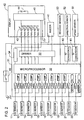
- FIG. 2 is a more detailed diagram of the above system
- FIG. 3 is a flow chart illustrating the operation of the above system.
- FIG. 1 there is shown an obstacle detection system for a vehicle in accordance with a preferred embodiment of the present invention.
- the system is adapted in use to be mounted on a vehicle 1 and comprises a plurality of ultrasonic wave sensors (hereinafter referred to simply as US sensors) 11 to 18 and two electromagnetic wave sensors (hereinafter referred to simply as EM sensors) 21 and 22.
- US sensors ultrasonic wave sensors
- EM sensors electromagnetic wave sensors
- Each of US sensors 11 to 18 transmits an ultrasonic wave pulse and receives a reflected ultrasonic wave pulse back from a target or obstacle, if any, around the vehicle to detect and locate the obstacle in a known manner. Due to detection characteristic of the US sensor, each US sensor gives a short detection range S1 to S8 with a relatively wide directivity around the vehicle for detection of a nearby obstacle. The detection and/or position of the obstacle is acknowledged at a detection unit 30 which is realized in an electronic control unit (ECU) 31 with a microprocessor 32 , as shown in FIG. 2 .
- ECU electronice control unit
- the EM sensors 21 and 22 are mounted at the front center and rear center of the vehicle 1 , respectively for monitoring forward and rearward fields of view from the vehicle 1 .
- Each of EM sensors 21 and 22 transmits an electromagnetic wave in a millimeter wave band, for example, 24 GHz and 76 - 77 GHz as an FM signal and receives a reflected FM signal from an obstacle, if any, at a remote distance from the vehicle to detect and located the obstacle in a known manner.
- Each of the front and rear EM sensors gives a long detection range L1 and L2 with a relatively narrow directivity for detection of a remote obstacle ahead and behind the vehicle.
- the position of the obstacle is determined at the same detection unit 30 based upon a frequency shifting between the transmitted and reflected FM signals, as is known in a radar detection system relying on an FWCW (frequency modulation continuous wave) process. It is equally possible to use the electromagnetic wave in a micrometer wave band.
- the system includes a speed sensor 51 for deriving a vehicle speed and a direction sensor 52 in the form of a steering wheel angle sensor for obtaining a direction of the vehicle to follow. Further, a reverse sensor 53 is provided for detection of a rearward movement of the vehicle 1 .
- Speed direction outputs from sensors 51 and 52 are fed respectively through a frequency-voltage conversion section 61 and 62 to the microprocessor 32 . Based upon the outputs from the sensors 51 to 53 , the microprocessor 32 controls the operation of the system as discussed later.
- a buzzer 41 and a display 42 are connected to the microprocessor 32 to constitute a warning unit for providing warnings to a driver based upon the detection of the nearby and remote obstacles.
- the buzzer 41 generates an intermittent buzzing sound of variable frequency (f1, f2) and intervals (T1, T2) for easy recognition by the driver as to which of the nearby or remote obstacle is detected. That is, the buzzer 41 gives off the buzzing sound of a low frequency (f1) with long intervals (T1) upon detection of the nearby obstacle at the detection unit 30 , while the buzzer 41 gives off the buzzing sound of a high frequency (f2) with a short intervals (T2) upon detection of the remote obstacle.
- f1 variable frequency
- T1 intervals
- the display 42 comprises a plurality of LEDs 43 which are arranged around a vehicle figure provided in a dashboard of the vehicle 1 to represent actual positions, i.e., front center, front left, front right, rear center, rear left, and rear right of the vehicle.
- the LEDs are connected to the microprocessor 32 through a driver 33 so that one or more of the LEDs corresponding to the detection range defined by the US sensors and EM sensors is turned on for immediate recognition by the driver of in which direction the nearby and/or remote obstacle is detected.
- the display 42 includes a selection switch 44 which deactivates the display as necessary.
- the display 41 includes a power source 45 which provides a stabilized operation voltage to a voltage source 34 of microprocessor 32 and LEDs 43 from a battery on the vehicle.
- a power switch 46 is provided between the battery and the power source 45 for energizing and deenergizing the system.
- a voice speaker may be incorporated to inform the driver of the detection of the nearby and/or remote obstacle by suitable voice warning messages, for example, "Caution!, nearby obstacle detected in front center” and the like.
- the microprocessor 32 is programmed to execute the operation as shown in the flow chart of FIG. 3 .
- a control is made to check whether the vehicle is moving forward or rearward.
- the direction of the vehicle is checked to perform respective routines as indicated. That is, when the vehicle is moving straight forward at a speed of 10 km/h or under, all of the US sensors 11 to 14 arranged on the front of the vehicle are activated for detection of the nearby obstacles in the respective short ranges S1 to S4 and at the same time the front EM sensor 21 is activated for detection of the remote obstacle in the long range L1 .
- the four or three selected ones of the US sensors 15 to 18 at the rear of the vehicle are activated together with the rear EM sensor 22 , depending upon the direction of the vehicle, as indicated in the flow chart.
- the vehicle direction is checked to shift directivity of the EM sensors 21 and 22 in match with an intended direction of the vehicle, either by varying the frequency of the FM signal or varying the angular orientation of the EM sensors 21 and 22 .
- the detection of the remote obstacles by thus adjusted EM sensors is notified by the buzzer 41 and the display 42 . Since the detection distance range L1 is shortened as the vehicle speed decrease, it is possible to exclude the detection of any far remote obstacle which is not dangerous to the vehicle and would otherwise cause over-sensitive warning, thereby assuring consistent and effective warning to the user sufficient for safe driving.
- the rear EM sensor 22 When moving the vehicle forward, the rear EM sensor 22 is activated to constantly detect the relative position of the remote obstacle behind the vehicle. Based upon the relative position of the obstacle behind the vehicle, the detection unit 30 acknowledges the obstacle as another vehicle approaching from behind when the position becomes closer, and cause a catching-up signal indicative of the presence of a caching-up vehicle.
- the catching-up signal is processed to give an alarm to the driver, for example, by generating the buzzing sound at a very short interval shorter than T1 and T2, and/or flashing all or some of the diodes.
- the voice message for example, "Alert!, another vehicle rushing behind" may be also effective.
- the detection unit 30 may include a memory for storing an updated position of the remote obstacles detected behind the vehicle, and a comparator which compares the current position of the obstacle with the last position for determination of whether the obstacle is moving closer and which issues the catching-up signal when the obstacle is determined to the catching-up vehicle.
- the buzzer, display and/or voice speaker is connected to receive the signal to give the corresponding alert to the driver.
- the position of the remote obstacle detected by EM sensors may be informed by displaying its distance and direction from the vehicle in an additional LCD or by a suitable voice message, such as "12 m ahead, direction one" which means the obstacle is located ahead at a distance of 12 in a direction of one o'clock on a clock indication with zero or twelve o'clock corresponding to straight forward.
- a suitable voice message such as "12 m ahead, direction one" which means the obstacle is located ahead at a distance of 12 in a direction of one o'clock on a clock indication with zero or twelve o'clock corresponding to straight forward.
- Each of the US sensors utilized in the system are selected to give a generally flat directivity with a small vertical beam angle of about 70° and a large horizontal angle of about 140° in order to eliminate unnecessary detection such as of a road surface when climbing up and down a road.
Landscapes
- Engineering & Computer Science (AREA)
- Radar, Positioning & Navigation (AREA)
- Remote Sensing (AREA)
- Physics & Mathematics (AREA)
- Computer Networks & Wireless Communication (AREA)
- General Physics & Mathematics (AREA)
- Acoustics & Sound (AREA)
- Electromagnetism (AREA)
- Measurement Of Velocity Or Position Using Acoustic Or Ultrasonic Waves (AREA)
- Radar Systems Or Details Thereof (AREA)
- Traffic Control Systems (AREA)
Claims (6)
- System zum Erkennen von Hindernissen für Kraftfahrzeuge, umfassend:eine Vielzahl von Ultraschallwellensensoren (11 bis 18), von denen jeder eine Ultraschallwelle um das Fahrzeug sendet und eine reflektierte Ultraschallwelle derselben zum Erkennen eines in der Nähe um das Fahrzeug befindlichen Hindernissen empfängt;einen Sensor (21) für elektromagnetische Wellen, der eine elektromagnetische Welle in einer Vorwärtsrichtung des Fahrzeugs sendet und eine reflektierte elektromagnetische Welle derselben zum Erkennen von fernen Hindernissen fern von dem Fahrzeug empfängt;einen Fahrzeuggeschwindigkeitssensor (51) zum Messen der Geschwindigkeit des Fahrzeugs und Liefern einer Geschwindigkeitsausgabe;eine Detektionseinheit (30), die das Vorhandensein eines in der Nähe befmdlichen Hindernisses auf der Grundlage der reflektierten Ultraschallwelle erkennt und die Position von fernen Hindernissen relativ zu dem Fahrzeug auf der Grundlage der reflektierten elektromagnetischen Welle erkennt, wobei die Detektionseinheit ein "Nahe"-Signal ausgibt, wenn ein nahes Hindernis erkannt wird, und ein "Fern"-Signal ausgibt, wenn sich die Position des fernen Hindernisses innerhalb einer vorab festgelegten langen Distanz von dem Fahrzeug befindet; undeine Warneinheit (41, 42), die jeweils als Antwort auf die "Nahe"- und "Fern"-Signale liefert,wobei die Detektionseinheit (30) zum Erkennen des Vorhandenseins eines nahen Hindernisses auf der Grundlage der reflektierten Ultraschallwelle und auch der Position eines fernen Hindernisses auf der Grundlage der reflektierten elektromagnetischen Welle konfiguriert ist, wenn die Geschwindigkeitsausgabe nicht größer als eine vorab festgelegte Referenzgeschwindigkeit ist, und die Position eines fernen Hindernisses nur auf der Grundlage der reflektierten elektromagnetischen Welle zu erkennen, wenn die Geschwindigkeitsausgabe die Referenzgeschwindigkeit überschreitet.
- System nach Anspruch 1, dadurch gekennzeichnet, dass die Detektionseinheit (30) zum Kürzen der vorab festgelegten langen Distanz zum Einengen eines Detektionsbereiches zum Erkennen eines fernen Hindernisses konfiguriert ist, wenn die Geschwindigkeitsausgabe vermindert ist.
- System nach Anspruch 1, ferner enthaltend einen Richtungssensor (52), der einen Lenkradwinkel des Fahrzeugs liefert, wobei der Sensor für elektromagnetische Wellen seine Wellensenderichtung in Abhängigkeit von dem Lenkradwinkel variiert.
- System nach Anspruch 1, ferner enthaltend eine hintere Sensoreinheit (22) für elektromagnetische Wellen, die eine elektromagnetische Welle in einer Rückwärtsrichtung des Fahrzeugs sendet und eine reflektierte elektromagnetische Welle derselben zum Erkennen eines fernen Hindernisses hinter dem Fahrzeug empfängt;
wobei die Detektionseinheit (30) die reflektierte elektromagnetische Welle von dem hinteren Sensor für elektromagnetische Wellen verarbeitet, um eine relative Position des fernen Hindernisses hinter dem Fahrzeug zu erkennen und das ferne Hindernis als ein weiteres Fahrzeug, das sich von hinten nähert, zu unterscheiden, wenn herausgefunden wird, dass sich die Position des fernen Hindernisses dem Fahrzeug nähert, und ein "Einhol"-Signal auszugeben, dass das Vorhandensein des weiteren Fahrzeugs angibt,
wobei die Warneinheit (41, 42) eine Warnung als Antwort auf das "Einhol"-Signal erzeugt. - System nach Anspruch 1, dadurch gekennzeichnet, dass die Warneinheit einen Summer (41) aufweist, der einen intermittierenden Summton erzeugt, dessen Intervall und/oder Frequenz entsprechend des Erkennens der nahen und fernen Hindernisse variiert.
- System nach Anspruch 1, dadurch gekennzeichnet, dass die Warneinheit einen Lautsprecher aufweist, der eine Sprachnachricht hinsichtlich des Erkennens des nahen und fernen Hindernisses erzeugt.
Applications Claiming Priority (2)
| Application Number | Priority Date | Filing Date | Title |
|---|---|---|---|
| JP10928298 | 1998-04-20 | ||
| JP10109282A JPH11301383A (ja) | 1998-04-20 | 1998-04-20 | 車載用障害物検知システム |
Publications (3)
| Publication Number | Publication Date |
|---|---|
| EP0952460A2 EP0952460A2 (de) | 1999-10-27 |
| EP0952460A3 EP0952460A3 (de) | 2000-07-26 |
| EP0952460B1 true EP0952460B1 (de) | 2009-06-24 |
Family
ID=14506226
Family Applications (1)
| Application Number | Title | Priority Date | Filing Date |
|---|---|---|---|
| EP99107302A Expired - Lifetime EP0952460B1 (de) | 1998-04-20 | 1999-04-19 | Vorrichtung zum Erkennen von Hindernissen für Kraftfahrzeuge |
Country Status (4)
| Country | Link |
|---|---|
| US (1) | US6281786B1 (de) |
| EP (1) | EP0952460B1 (de) |
| JP (1) | JPH11301383A (de) |
| DE (1) | DE69941021D1 (de) |
Cited By (2)
| Publication number | Priority date | Publication date | Assignee | Title |
|---|---|---|---|---|
| CN105467394A (zh) * | 2014-08-27 | 2016-04-06 | 现代摩比斯株式会社 | 停车空间探索装置及其探索方法 |
| RU2715599C1 (ru) * | 2019-01-18 | 2020-03-02 | Акционерное общество "Черногорский ремонтно-механический завод" (АО "Черногорский РМЗ") | Система противоаварийной безопасности |
Families Citing this family (54)
| Publication number | Priority date | Publication date | Assignee | Title |
|---|---|---|---|---|
| JP2000168476A (ja) * | 1998-09-29 | 2000-06-20 | Denso Corp | 車両用複合装置 |
| SE520360C2 (sv) * | 1999-12-15 | 2003-07-01 | Goeran Sjoenell | Varningsanordning vid fordon |
| DE19963755A1 (de) | 1999-12-30 | 2001-07-12 | Bosch Gmbh Robert | Abstandssensorvorrichtung |
| IL141790A (en) | 2000-03-27 | 2006-10-05 | Pdm Co Ltd | System and method for insurance charges for vehicles |
| US6594614B2 (en) * | 2000-04-17 | 2003-07-15 | Delphi Technologies, Inc. | Vehicle back-up aid system |
| US20020065564A1 (en) * | 2000-07-13 | 2002-05-30 | Sheriff Amyn A. | Digital content management system |
| KR100523367B1 (ko) | 2000-10-26 | 2005-10-20 | 마츠시다 덴코 가부시키가이샤 | 장해물 회피기능을 가지는 자율이동장치 |
| JP4522002B2 (ja) * | 2001-02-22 | 2010-08-11 | 株式会社小松製作所 | 作業車両の後退操作検出装置 |
| DE20106977U1 (de) * | 2001-04-23 | 2002-08-29 | Mekra Lang Gmbh & Co Kg | Warneinrichtung in Kraftfahrzeugen |
| WO2003029045A2 (en) * | 2001-10-03 | 2003-04-10 | Sense Technologies, Inc. | Multi-technology object detection system and method |
| US7127369B2 (en) * | 2001-10-09 | 2006-10-24 | Siemens Vdo Automotive Corporation | Sensor assembly |
| GB2382708B (en) * | 2001-11-21 | 2006-03-15 | Roke Manor Research | Detection of foreign objects on surfaces |
| US6803858B2 (en) | 2002-04-29 | 2004-10-12 | Sandra Whitted | Blind spot alert system |
| JP2004050925A (ja) * | 2002-07-18 | 2004-02-19 | Advics:Kk | 駐車補助ブレーキ装置 |
| US6784791B2 (en) * | 2002-07-25 | 2004-08-31 | Ford Global Technologies, Llc | Potential collision detection and parking aid system |
| DE10234574A1 (de) * | 2002-07-30 | 2004-02-19 | Valeo Schalter Und Sensoren Gmbh | Fahrzeugumfeldüberwachungssystem und Verfahren hierfür |
| JP3782409B2 (ja) * | 2002-08-30 | 2006-06-07 | 積水樹脂株式会社 | 移動体距離検出システム |
| US7106213B2 (en) * | 2002-10-28 | 2006-09-12 | General Motors Corporation | Distance detection and display system for use in a vehicle |
| US6793177B2 (en) * | 2002-11-04 | 2004-09-21 | The Bonutti 2003 Trust-A | Active drag and thrust modulation system and method |
| JP4021401B2 (ja) * | 2003-11-07 | 2007-12-12 | 本田技研工業株式会社 | 車両用物体検知装置 |
| WO2005073754A1 (en) | 2004-02-02 | 2005-08-11 | Sjoenell Goeran | Vehicle collision detector |
| JP4283697B2 (ja) * | 2004-02-05 | 2009-06-24 | 株式会社デンソー | 車両用障害物検知装置 |
| US7046128B2 (en) * | 2004-05-26 | 2006-05-16 | Roberts Kristie L | Collision detection and warning system for automobiles |
| US8629800B2 (en) * | 2004-09-30 | 2014-01-14 | The Boeing Company | Ground vehicle collision prevention systems and methods |
| US7379165B2 (en) * | 2004-09-30 | 2008-05-27 | The Boeing Company | Ground vehicle collision prevention systems and methods |
| US7586032B2 (en) | 2005-10-07 | 2009-09-08 | Outland Research, Llc | Shake responsive portable media player |
| CN2852149Y (zh) * | 2005-10-11 | 2006-12-27 | 李植滔 | 带警示有车靠近的倒车雷达 |
| US20070162550A1 (en) * | 2006-01-06 | 2007-07-12 | Outland Research, Llc | Vehicle-to-vehicle instant messaging with locative addressing |
| US8121730B2 (en) * | 2006-10-02 | 2012-02-21 | Industrial Technology Research Institute | Obstacle detection device of autonomous mobile system |
| DE102006057230A1 (de) * | 2006-12-05 | 2008-07-03 | Volkswagen Ag | Parklenkassistenzsystem mit verbesserter Ein- und Ausschaltlogik |
| US7557692B2 (en) * | 2006-12-19 | 2009-07-07 | Shih-Hsiung Li | Fast detecting obstacle method and parking sensor apparatus using the same |
| JP2009069022A (ja) * | 2007-09-13 | 2009-04-02 | Panasonic Corp | レーダ装置、その制御方法及び車両 |
| EP2144086A1 (de) * | 2008-07-10 | 2010-01-13 | Valeo Schalter und Sensoren GmbH | Verfahren und Vorrichtung zur Steuerung eines Parkassistenzsystems für Fahrzeuge |
| JP5282730B2 (ja) * | 2009-12-15 | 2013-09-04 | トヨタ自動車株式会社 | 運転支援装置 |
| FR2958245B1 (fr) * | 2010-04-06 | 2012-05-04 | Peugeot Citroen Automobiles Sa | Dispositif et procede d'aide aux man?uvres d'un vehicule a duree de fonctionnement controlee |
| CN102844674A (zh) * | 2010-04-15 | 2012-12-26 | 松下电器产业株式会社 | 障碍物检测系统 |
| US9415774B2 (en) | 2011-09-22 | 2016-08-16 | Nissan Motor Co., Ltd. | Vehicle control apparatus including an obstacle detection device |
| CN103675761A (zh) * | 2012-09-17 | 2014-03-26 | 深圳市豪恩电子科技股份有限公司 | 倒车雷达显示器显示方法及倒车雷达显示器 |
| DE102012218280A1 (de) * | 2012-10-08 | 2014-04-10 | Robert Bosch Gmbh | Verfahren und Vorrichtung zur Latenzzeitoptimierung bei einer Abstandsmessung mittels mehrerer Sensoren |
| JP6175863B2 (ja) * | 2013-03-29 | 2017-08-09 | 富士通株式会社 | レーダ装置及びプログラム |
| CN104139730A (zh) * | 2013-05-09 | 2014-11-12 | 银剑无线电话股份有限公司 | 车辆测距警示装置 |
| US9306622B2 (en) * | 2014-09-10 | 2016-04-05 | Honeywell International Inc. | Non-contact sensing and reading of signals transmitted by a cable |
| KR102327649B1 (ko) * | 2015-06-12 | 2021-11-17 | 현대모비스 주식회사 | 차량거리유지장치 및 차량거리유지방법 |
| JP6945399B2 (ja) * | 2017-09-13 | 2021-10-06 | 株式会社クボタ | 障害物検出装置 |
| CN109747643B (zh) * | 2017-11-07 | 2022-08-12 | 宇通客车股份有限公司 | 一种智能车辆感知系统的信息融合方法 |
| DE102018107827A1 (de) * | 2018-04-03 | 2019-10-10 | Valeo Schalter Und Sensoren Gmbh | Ultraschallsensor mit Powerline-Kommunikation |
| WO2020075686A1 (ja) * | 2018-10-12 | 2020-04-16 | 京セラ株式会社 | 電子機器、電子機器の制御方法、及び電子機器の制御プログラム |
| RU2706798C1 (ru) * | 2019-01-18 | 2019-11-21 | Общество с ограниченной ответственностью "АВРОРА РОБОТИКС" | Ультразвуковая система обнаружения препятствий движению беспилотного транспортного средства |
| JP7204612B2 (ja) * | 2019-08-06 | 2023-01-16 | 株式会社東芝 | 位置姿勢推定装置、位置姿勢推定方法及びプログラム |
| CN111324124A (zh) * | 2020-03-06 | 2020-06-23 | 新石器慧通(北京)科技有限公司 | 一种无人车遥控控制方法、控制系统及无人车 |
| JP7276282B2 (ja) * | 2020-08-24 | 2023-05-18 | トヨタ自動車株式会社 | 物体検出装置、物体検出方法及び物体検出用コンピュータプログラム |
| JP7776367B2 (ja) * | 2022-03-28 | 2025-11-26 | 本田技研工業株式会社 | 支援装置、車両、プログラム、及び支援方法 |
| JP2025002782A (ja) * | 2023-06-23 | 2025-01-09 | キヤノン株式会社 | 情報処理装置 |
| JP7717126B2 (ja) * | 2023-08-10 | 2025-08-01 | 本田技研工業株式会社 | 支援装置、車両、プログラム、及び支援方法 |
Family Cites Families (10)
| Publication number | Priority date | Publication date | Assignee | Title |
|---|---|---|---|---|
| US4467313A (en) * | 1980-11-14 | 1984-08-21 | Nippon Soken, Inc. | Automotive rear safety checking apparatus |
| US5530651A (en) * | 1992-08-03 | 1996-06-25 | Mazda Motor Corporation | Running-safety system for an automotive vehicle |
| US5714928A (en) * | 1992-12-18 | 1998-02-03 | Kabushiki Kaisha Komatsu Seisakusho | System for preventing collision for vehicle |
| US5347273A (en) * | 1993-01-14 | 1994-09-13 | Kamyar Katiraie | Adjustable, ultrasonic collision warning system |
| JP3183598B2 (ja) * | 1993-12-14 | 2001-07-09 | 三菱電機株式会社 | 障害物検知装置 |
| US5594413A (en) * | 1993-12-27 | 1997-01-14 | Hyundai Electronics Industries Co., Ltd. | Car collision prevention apparatus and method using dual processor and automatic sensor switching function |
| JP3302848B2 (ja) | 1994-11-17 | 2002-07-15 | 本田技研工業株式会社 | 車載レーダー装置 |
| US5767793A (en) * | 1995-04-21 | 1998-06-16 | Trw Inc. | Compact vehicle based rear and side obstacle detection system including multiple antennae |
| GB9601691D0 (en) | 1996-01-27 | 1996-03-27 | Rover Group | A cruise control system for a motor vehicle |
| JPH09301068A (ja) * | 1996-05-13 | 1997-11-25 | Niles Parts Co Ltd | 電子フラッシャ装置 |
-
1998
- 1998-04-20 JP JP10109282A patent/JPH11301383A/ja active Pending
-
1999
- 1999-04-19 EP EP99107302A patent/EP0952460B1/de not_active Expired - Lifetime
- 1999-04-19 DE DE69941021T patent/DE69941021D1/de not_active Expired - Lifetime
- 1999-04-19 US US09/293,961 patent/US6281786B1/en not_active Expired - Lifetime
Cited By (3)
| Publication number | Priority date | Publication date | Assignee | Title |
|---|---|---|---|---|
| CN105467394A (zh) * | 2014-08-27 | 2016-04-06 | 现代摩比斯株式会社 | 停车空间探索装置及其探索方法 |
| CN105467394B (zh) * | 2014-08-27 | 2017-10-20 | 现代摩比斯株式会社 | 停车空间探索装置及其探索方法 |
| RU2715599C1 (ru) * | 2019-01-18 | 2020-03-02 | Акционерное общество "Черногорский ремонтно-механический завод" (АО "Черногорский РМЗ") | Система противоаварийной безопасности |
Also Published As
| Publication number | Publication date |
|---|---|
| US6281786B1 (en) | 2001-08-28 |
| DE69941021D1 (de) | 2009-08-06 |
| EP0952460A2 (de) | 1999-10-27 |
| EP0952460A3 (de) | 2000-07-26 |
| JPH11301383A (ja) | 1999-11-02 |
Similar Documents
| Publication | Publication Date | Title |
|---|---|---|
| EP0952460B1 (de) | Vorrichtung zum Erkennen von Hindernissen für Kraftfahrzeuge | |
| AU2002211733B2 (en) | Collision avoidance method and system | |
| US5754123A (en) | Hybrid ultrasonic and radar based backup aid | |
| AU2002211733A1 (en) | Collision avoidance method and system | |
| US5467072A (en) | Phased array based radar system for vehicular collision avoidance | |
| EP1261957B1 (de) | Detektor für toten winkel | |
| US4349823A (en) | Automotive radar monitor system | |
| US6362749B1 (en) | Emergency vehicle detection system | |
| JP6203862B2 (ja) | 警告領域、特に、死角における物標の存在に基づいて自動車において警告信号を維持する方法、対応する運転者支援システムおよび自動車 | |
| EP0655142B1 (de) | Intelligenter totwinkelerfassungssensor | |
| EP0740166B1 (de) | Kompaktes fahrzeuggestütztes System mit Mehrfachantennen zum rückwärtigen und seitlichen Erkennen von Hindernissen | |
| WO1998000728A1 (en) | Motor road vehicle collision warning system | |
| KR101743721B1 (ko) | 자전거 충돌 방지 장치 | |
| JPH06162396A (ja) | 車載用安全運転支援装置 | |
| JPH07105500A (ja) | 交差点警報方式 | |
| GB2405474A (en) | Parking aid system | |
| KR100507090B1 (ko) | 차량의 추돌 경보장치 및 그 방법 | |
| US20070080793A1 (en) | Auto brake alert | |
| US6832137B2 (en) | Leaky cable based method and system for automotive parking aid, reversing aid, and pre-collision sensing | |
| US20060071764A1 (en) | Merge Sensor Control System | |
| KR20160132220A (ko) | 자동차 사각지대 경보장치 및 그 방법 | |
| GB2266369A (en) | Vehicle manoeuvring aid | |
| GB2254509A (en) | Safety device for a vehicle | |
| KR100514479B1 (ko) | 후방 충돌 경보장치용 초음파 센서 장치 | |
| JP2000338248A (ja) | 自動車用レーザレーダ装置 |
Legal Events
| Date | Code | Title | Description |
|---|---|---|---|
| PUAI | Public reference made under article 153(3) epc to a published international application that has entered the european phase |
Free format text: ORIGINAL CODE: 0009012 |
|
| AK | Designated contracting states |
Kind code of ref document: A2 Designated state(s): DE FR |
|
| AX | Request for extension of the european patent |
Free format text: AL;LT;LV;MK;RO;SI |
|
| PUAL | Search report despatched |
Free format text: ORIGINAL CODE: 0009013 |
|
| AK | Designated contracting states |
Kind code of ref document: A3 Designated state(s): AT BE CH CY DE DK ES FI FR GB GR IE IT LI LU MC NL PT SE |
|
| AX | Request for extension of the european patent |
Free format text: AL;LT;LV;MK;RO;SI |
|
| 17P | Request for examination filed |
Effective date: 20001023 |
|
| AKX | Designation fees paid |
Free format text: DE FR |
|
| 17Q | First examination report despatched |
Effective date: 20070507 |
|
| GRAP | Despatch of communication of intention to grant a patent |
Free format text: ORIGINAL CODE: EPIDOSNIGR1 |
|
| RAP1 | Party data changed (applicant data changed or rights of an application transferred) |
Owner name: PANASONIC ELECTRIC WORKS CO., LTD. |
|
| GRAS | Grant fee paid |
Free format text: ORIGINAL CODE: EPIDOSNIGR3 |
|
| GRAA | (expected) grant |
Free format text: ORIGINAL CODE: 0009210 |
|
| AK | Designated contracting states |
Kind code of ref document: B1 Designated state(s): DE FR |
|
| REF | Corresponds to: |
Ref document number: 69941021 Country of ref document: DE Date of ref document: 20090806 Kind code of ref document: P |
|
| PLBE | No opposition filed within time limit |
Free format text: ORIGINAL CODE: 0009261 |
|
| STAA | Information on the status of an ep patent application or granted ep patent |
Free format text: STATUS: NO OPPOSITION FILED WITHIN TIME LIMIT |
|
| 26N | No opposition filed |
Effective date: 20100325 |
|
| PGFP | Annual fee paid to national office [announced via postgrant information from national office to epo] |
Ref country code: FR Payment date: 20140409 Year of fee payment: 16 Ref country code: DE Payment date: 20140430 Year of fee payment: 16 |
|
| REG | Reference to a national code |
Ref country code: DE Ref legal event code: R119 Ref document number: 69941021 Country of ref document: DE |
|
| PG25 | Lapsed in a contracting state [announced via postgrant information from national office to epo] |
Ref country code: DE Free format text: LAPSE BECAUSE OF NON-PAYMENT OF DUE FEES Effective date: 20151103 |
|
| REG | Reference to a national code |
Ref country code: FR Ref legal event code: ST Effective date: 20151231 |
|
| PG25 | Lapsed in a contracting state [announced via postgrant information from national office to epo] |
Ref country code: FR Free format text: LAPSE BECAUSE OF NON-PAYMENT OF DUE FEES Effective date: 20150430 |