EP0952464B1 - Verfahren zum Lokalisieren eines Unterseekabels und Energieversorgungsschaltkreis für dieses Kabel - Google Patents
Verfahren zum Lokalisieren eines Unterseekabels und Energieversorgungsschaltkreis für dieses Kabel Download PDFInfo
- Publication number
- EP0952464B1 EP0952464B1 EP99301844A EP99301844A EP0952464B1 EP 0952464 B1 EP0952464 B1 EP 0952464B1 EP 99301844 A EP99301844 A EP 99301844A EP 99301844 A EP99301844 A EP 99301844A EP 0952464 B1 EP0952464 B1 EP 0952464B1
- Authority
- EP
- European Patent Office
- Prior art keywords
- signal
- toning
- signal waveform
- square wave
- peak
- Prior art date
- Legal status (The legal status is an assumption and is not a legal conclusion. Google has not performed a legal analysis and makes no representation as to the accuracy of the status listed.)
- Expired - Lifetime
Links
- 238000000034 method Methods 0.000 title claims description 13
- 230000005540 biological transmission Effects 0.000 claims description 8
- 230000004044 response Effects 0.000 claims description 4
- 230000003287 optical effect Effects 0.000 description 18
- 238000010586 diagram Methods 0.000 description 6
- 230000002238 attenuated effect Effects 0.000 description 4
- 230000006872 improvement Effects 0.000 description 3
- 230000000694 effects Effects 0.000 description 2
- 230000006870 function Effects 0.000 description 2
- 230000008439 repair process Effects 0.000 description 2
- 230000008859 change Effects 0.000 description 1
- 238000006243 chemical reaction Methods 0.000 description 1
- 230000001066 destructive effect Effects 0.000 description 1
- 238000001514 detection method Methods 0.000 description 1
- 238000007689 inspection Methods 0.000 description 1
- 238000012423 maintenance Methods 0.000 description 1
- 239000013307 optical fiber Substances 0.000 description 1
- 230000001360 synchronised effect Effects 0.000 description 1
- 230000005428 wave function Effects 0.000 description 1
Images


Classifications
-
- G—PHYSICS
- G01—MEASURING; TESTING
- G01V—GEOPHYSICS; GRAVITATIONAL MEASUREMENTS; DETECTING MASSES OR OBJECTS; TAGS
- G01V3/00—Electric or magnetic prospecting or detecting; Measuring magnetic field characteristics of the earth, e.g. declination, deviation
- G01V3/02—Electric or magnetic prospecting or detecting; Measuring magnetic field characteristics of the earth, e.g. declination, deviation operating with propagation of electric current
- G01V3/06—Electric or magnetic prospecting or detecting; Measuring magnetic field characteristics of the earth, e.g. declination, deviation operating with propagation of electric current using AC
Definitions
- the present invention relates to a fault location toning method for submarine networks and in particular, a method of increasing the propagation distance of a low frequency tone.
- the maximum amplitude of a toning signal generated by the power feed equipment is limited by the electrical characteristics of amplifiers within optical repeaters provided at intervals along the length of the submarine cable, which are sensitive to the negative half cycle of the toning signal.
- repeaters will incorporate state of the art amplifiers which operate at much lower currents so that the expected maximum toning amplitude will be around 200 mA peak to peak. A toning signal at this amplitude would not be expected to propagate any great distance and still be detectable. Since ship time is expensive any decrease in toning distance could be costly.
- a method of locating the position of a fault in a submarine cable is known from JP 07 240704 A (NEC MIYAGI LTD) which relates to detecting the position of the fault by using a magnetic field generated by an AC signal which is superposed on a DC current sent along the submarine cable.
- a magnetic sensor is hung down from a repairing ship to the sea bottom toward the submarine cable in order to detect the magnetic field generated by the AC signal throughout the submarine cable. Then the magnetic sensor is moved around the cable until it reaches a point where the magnetic field is not detected this being indicative of a fault position.
- the AC signal is superposed on the DC signal only at predetermined time intervals, this being done by turning on and off the AC signal as a result of combining the latter with a square wave having on off periods according to the predetermined time intervals desired for the detection of the AC signal.
- a further method for detecting fault in a cable is known from US-A-5 210 49.7.
- three signals are applied to the cable, two of them being of high frequency and the third signal of low frequency being an integer multiple of the difference between the frequencies of the first two high frequency signals.
- the low and the high frequencies are then detected separately and the two high frequencies are processed in order to obtain a synchronous low frequency reference signal which is then compared to the original low frequency signal.
- a method of locating a submarine cable, according to claim 1 is provided.
- each of the first signal waveform and second signal waveform is sinusoidal. More preferably, the second signal waveform is of a higher frequency than the first signal waveform.
- the toning signal is a square wave, wherein the first signal waveform corresponds to the fundamental frequency and the second and any subsequent signal waveforms corresponds to a respective one of the harmonic frequencies.
- a number of the harmonics of the square wave are pre-emphasised by a predetermined amount to take account of the frequency response of the submarine cable.
- a power feed circuit for a submarine cable according to claim 6 is provided.
- the toning signal control circuit comprises a digital signal processor which is arranged to cycle through a look-up table stored in a memory and output a series of sample values which are used to control the electrical output of the power feed circuit.
- the contents of the look-up table stored in memory define a complete cycle of a square wave. More preferably. the sample values in the look-up table are effective to provide a degree of pre-emphasis to the harmonics of the square wave toning signal.
- the present invention provides a way of offsetting the loss of transmission distance due to the use of state of the art optical repeaters. It is proposed to optimise the shape of the toning signal so that more current can be launched into the submarine cable without damaging the repeaters and thereby extend significantly the useful toning distance. If a square wave is used, the amplitude of the fundamental is around 20% higher than the peak of the total wave. A further improvement can be obtained by utilising the fact that the higher frequency components of the square wave toning signal will be attenuated more strongly by the submarine cable than those at a lower frequency. In particular, the toning signal wave shape is changed significantly between the power feed and first repeater and this can be compensated for by increasing the amplitude of the higher harmonics so that by the time it gets to the repeater it has a maximum acceptable amplitude square wave.
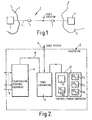
- Figure 1 shows a simplified example of a submarine communcations system 1 which consists of a first endstation 2 located on one land mass 3 and a second endstation 4 located on another land mass 5, with the two endstations connected by a submarine cable 6.
- the submarine cable 6 includes a number of optical repeaters 7 spaced apart at intervals along the length of the cable.
- the submarine cable 6 is powered by power feed equipment (PFE) (not shown) located at each of the endstations. Power is required to operate the optical repeaters 7 and any branching units (not shown) in the cable system.
- PFE power feed equipment
- FIG. 2 shows a block diagram of the main elements of an endstation 2.
- the endstation 2 includes transmission terminal equipment 8 which has a number of I/O ports 9 for links which carry customer traffic.
- the transmission terminal equipment 8 is arranged to multiplex incoming data streams to form a WDM optical signal which is coupled by an optical fibre 10 to a cable termination 11.
- the cable termination 11 also receives and secures the end of the submarine cable 6. which is powered from a power feed circuit 12.
- a WDM optical signal received by the endstation 2 is coupled to the transmission terminal equipment 8 via the cable termination 11, where the individual channels are demultiplexed and directed to a respective I/O port 9 for onward transmission to customers.
- the power feed circuit 12 includes a control circuit 13 for superimposing a toning signal on the working current provided by a number of series connected 50 V/2.5 KV power converters 14 1 to 14 4 .
- FIG 3 is a block diagram of the power feed circuit 12.
- the power feed circuit includes a digital signal processor (DSP) 15 for generating a series of set point coefficients (arranged in a table of output current against time) which are used to control the current output of what is effectively a DC-DC 50 V/10 KV power converter 14 and so provide a square wave toning signal on the submarine cable 6.
- DSP digital signal processor
- the DSP 15 is shown in more detail in Figure 4 and will be described in detail below.
- Each set point coefficient generated by the DSP 15 is a digital value which is converted to an analog signal by a digital to analog converter 16.
- the analog signal is input to a pulse width modulator (PWM) 17, the output of which is converted to an optical signal at an optical interface 18 of the power feed circuit.
- PWM pulse width modulator
- the optical signal (a series of pulses) is subsequently used to control the output of the power converter 14.
- the optical pulses are converted back to an electrical signal on board the power convector circuit and used to switch the converter transistors so that the output current from the power converters is the same as the value entered into the control loop as the DSP 15 steps through the table of set point coefficients.
- the output of the power converter 14 is monitored by a current monitor 19, a signal from which is passed to the optical interface 18 after conversion by an analog to digital converter 20.
- the electrical output of the optical interface is fed back in a positive feedback path 21 where it is combined with the set point coefficient output of the DSP 15.
- the DSP 15 is arranged to output a series of values which is periodically repeated to generate a low frequency square wave toning signal. As will be described below, it is also possible for the DSP 15 to output suitable coefficients which apply a varying degree of pre-emphasis to the harmonics of the square wave to compensate for the known frequency response of the submarine cable 6 and thereby increase the propagation potential still further.
- FIG 4 shows a block diagram of the DSP 15 for generating the set point coefficeints used to derive a square wave toning signal.
- the DSP 15 comprises a control system which receives inputs (peak to peak current and frequency) from a user interface 23.
- the control system 22 controls a counter 24 which operates at a rate corresponding to the desired frequency of the toning signal.
- the control system 22 accesses a look-up table 25 stored in a memory which holds a number of sample values and is operative to output each sample value in sequence as the set point coefficient output for the system.
- the complete sequence of samples defines the coefficients for generating one complete cycle of a square wave.
- the coefficients shown are for a 200mA peak to peak square wave (nominal 1100mA).
- Each of the fundamental and the harmonics of the square wave can be considered as a separate sine wave.
- the amplitude of the fundamental in a square wave is typically 20% higher than the peak of the total wave so that a fundamental of, for example, 250 mA peak to peak, would be obtained from a square wave of 200 mA peak to peak. This is because the amplitude of the fundamental in a square wave is suppressed by destructive interference with the odd order harmonics. This means that the fundamental frequency component can propagate further. The effect of the harmonics tends to diminish with propagation distance until only the fundamental remains. This is illustrated in Figures 5A to 5D.
- the square wave toning signal propagates through a series of four optical repeaters at a distance of 40 km (Figure 5A), 80 km (Figure 5B) and 160 km (Figure 5D) from the powerfeed, respectively.
- the toning signal after the fourth repeater is substantially a sine wave with a frequency corresponding to the fundamental of the original square wave generated by the power feed.
- the peak to peak amplitude is attenuated to around 3.5 mA. which is still detectable.
- a further improvement can be made at least over the first link from the endstation to a first optical repeater. It is possible to adjust the sample values in the look-up table 25 to give some pre-emphasis to the higher frequency harmonics to enable the amplitude of the fundamental frequency component to be increased still further without any apparent increase in the peak to peak amplitude of the square wave by the time it reaches the first optical repeater. This allows the toning signal (the fundamental) to propagate further.
- FIG. 6A to 6D An example of this is illustrated in Figures 6A to 6D.
- the square wave toning signal with pre-emphasis propagates through a series of four optical repeaters at a distance of 40 km (Figure 6B), 80 km (Figure 6C) and 160 km (Figure 6D) from the powerfeed, respectively.
- Figure 6B the peak to peak amplitude of the toning signal is around 4 mA after the fourth repeater, which represents a significant improvement.
- the present invention provides a way of off-setting the loss of transmission distance due to the use of state of the art optical repeaters.
- the ability of a ship to detect a toning signal greatly speeds up repair and maintenance operations. Since ship time is enormously expensive, any increase in the effective distance from shore will result in a cost saving.
Landscapes
- Life Sciences & Earth Sciences (AREA)
- General Life Sciences & Earth Sciences (AREA)
- Environmental & Geological Engineering (AREA)
- Geology (AREA)
- Remote Sensing (AREA)
- Physics & Mathematics (AREA)
- Engineering & Computer Science (AREA)
- General Physics & Mathematics (AREA)
- Geophysics (AREA)
- Optical Communication System (AREA)
- Cable Transmission Systems, Equalization Of Radio And Reduction Of Echo (AREA)
- Testing Of Optical Devices Or Fibers (AREA)
- Insulated Conductors (AREA)
Claims (9)
- Verfahren zum Lokalisieren eines Unterseekabels (6) durch Erkennen eines Tonsignals, wobei das Unterseekabel (6) mindestens einen Zwischenverstärker (7) beinhaltet, wobei das Verfahren den Schritt des Übertragens des Tonsignals entlang dem Unterseekabel (6) umfaßt, dadurch gekennzeichnet, daß das Tonsignal eine erste Signalwellenform umfaßt, die zu erkennen ist, die mit mindestens einer zweiten Signalwellenform kombiniert ist, wobei sich die zweite Signalwellenform mit der ersten Signalwellenform überlagert, um die Spitzenamplitude des Tonsignals zur Übertragung zu begrenzen, so daß die resultierende begrenzte Spitzenamplitude mit den elektrischen Charakteristika des mindestens einen Zwischenverstärkers (7) kompatibel ist.
- Verfahren nach Anspruch 1, in welchem jede der ersten Signalwellenform und zweiten Signalwellenform sinusförmig ist.
- Verfahren nach Anspruch 1 oder 2, in welchem die zweite Signalwellenform von höherer Frequenz als die erste Signalwellenform ist.
- Verfahren nach einem vorhergehenden Anspruch, in welchem das Tonsignal eine Rechteckwelle ist, wobei die erste Signalwellenform der Grundfrequenz entspricht und die zweite und jede nachfolgende Signalwellenform einer entsprechenden der harmonischen Frequenzen entspricht.
- Verfahren nach Anspruch 4, in welchem mehrere der Oberwellen der Rechteckwelle um einen vorgegebenen Wert vorverzerrt werden, um die Frequenzkennlinie des Unterseekabels (6) zu berücksichtigen, wobei die Vorverzerrung durch Erhöhen der Amplitude der höheren Oberwellen durchgeführt wird, so daß in der Zeit, in der das Tonsignal den Zwischenverstärker (7) erreicht, es eine maximale annehmbare Amplitudenrechteckwelle aufweist.
- stromversorgungsschaltung (12) für ein Unterseekabel (6), die mindestens einen Zwischenverstärker (7) beinhaltet, der eine Tonsignalsteuerschaltung (13) umfaßt, die konfiguriert ist, um ein elektrisches Ausgangssignal der Stromversorgungsschaltung (12) zu modulieren, um ein Tonsignal bereitzustellen, das zu erkennen ist, um das Unterseekabel (6) zu lokalisieren, dadurch gekennzeichnet, daß das Tonsignal eine erste Signalwellenform umfaßt, welche zu erkennen ist, die mit mindestens einer zweiten Signalwellenform kombiniert ist, wobei sich die zweite Signalwellenform mit der ersten Signalwellenform überlagert, um die Spitzenamplitude des Tonsignals zur Übertragung zu begrenzen, so daß die resultierende begrenzte Spitzenamplitude mit den elektrischen Charakteristika des mindestens einen Zwischenverstärkers (7) kompatibel ist.
- Stromversorgungsschaltung nach Anspruch 6, in welcher die Tonsignalsteuerschaltung (13) einen digitalen Signalprozessor (15) umfaßt, welcher angeordnet ist, um periodisch eine Nachschlagetabelle (25) zu durchlaufen, die in einem Speicher gespeichert ist, und um eine Reihe von Abtastwerten auszugeben, die verwendet werden, um den elektrischen Ausgang der Stromversorgungsschaltung (12) zu steuern.
- Stromversorgungsschaltung nach Anspruch 7, in welcher der Inhalt der Nachschlagetabelle (25), der im Speicher gespeichert ist, eine vollständige Periode einer Rechteckwelle definiert.
- stromversorgungsschaltung nach Anspruch 8, in welcher die Abtastwerte in der Nachschlagetabelle (25) nutzbar sind, um einen Grad der Vorverzerrung der Oberwellen der Rechteckwelle bereitzustellen, wobei die Vorverzerrung durch Erhöhen der Amplitude der höheren Oberwellen durchgeführt wird, so daß in der Zeit, bis das Tonsignal den Zwischenverstärker (7) erreicht, es eine maximale annehmbare Amplitudenrechteckwelle aufweist.
Applications Claiming Priority (2)
| Application Number | Priority Date | Filing Date | Title |
|---|---|---|---|
| GBGB9806190.6A GB9806190D0 (en) | 1998-03-23 | 1998-03-23 | A fault location toning method for submarine networks |
| GB9806190 | 1998-03-23 |
Publications (3)
| Publication Number | Publication Date |
|---|---|
| EP0952464A2 EP0952464A2 (de) | 1999-10-27 |
| EP0952464A3 EP0952464A3 (de) | 2002-03-13 |
| EP0952464B1 true EP0952464B1 (de) | 2005-12-28 |
Family
ID=10829086
Family Applications (1)
| Application Number | Title | Priority Date | Filing Date |
|---|---|---|---|
| EP99301844A Expired - Lifetime EP0952464B1 (de) | 1998-03-23 | 1999-03-11 | Verfahren zum Lokalisieren eines Unterseekabels und Energieversorgungsschaltkreis für dieses Kabel |
Country Status (5)
| Country | Link |
|---|---|
| US (1) | US6278655B2 (de) |
| EP (1) | EP0952464B1 (de) |
| JP (1) | JPH11326117A (de) |
| DE (1) | DE69929107T2 (de) |
| GB (1) | GB9806190D0 (de) |
Families Citing this family (11)
| Publication number | Priority date | Publication date | Assignee | Title |
|---|---|---|---|---|
| US7113706B2 (en) * | 2001-08-13 | 2006-09-26 | Lee Feinberg | Systems and methods for placing line terminating equipment of optical communication systems in customer points of presence |
| US20040105136A1 (en) * | 2001-05-08 | 2004-06-03 | Corvis Corporation | Interconnections and protection between optical communications networks |
| GB0128622D0 (en) * | 2001-11-29 | 2002-01-23 | Global Marine Systems Ltd | Optical cable repeater |
| JP2004172679A (ja) * | 2002-11-15 | 2004-06-17 | Matsushita Electric Ind Co Ltd | 撮像装置 |
| DE102004013492B4 (de) * | 2004-03-18 | 2015-06-11 | Michael Kurth | Vorrichtung, handtragbares Testgerät und Verfahren zum Einkoppeln von elektrischen Signalen in Leitungen oder Kabel zu Ortungszwecken |
| US20080050121A1 (en) * | 2004-06-17 | 2008-02-28 | Evangelides Stephen G | Submarine optical transmission systems having optical amplifiers of unitary design |
| US8537730B2 (en) * | 2005-03-03 | 2013-09-17 | Thomson Licensing | Method and apparatus for sensing channel availability in wireless networks |
| CN102735996B (zh) * | 2012-07-17 | 2014-12-03 | 国家电网公司 | 一种海底电缆故障点准确定位方法 |
| CN105277853B (zh) * | 2015-11-11 | 2018-04-20 | 东北大学 | 一种基于二次脉冲的海底电缆故障定位装置及方法 |
| CN106323596B (zh) * | 2016-09-12 | 2019-05-17 | 哈尔滨工程大学 | 一种保偏光纤缺陷点检测中对干涉峰的位置-幅值含义预估方法 |
| US11736671B2 (en) * | 2020-06-02 | 2023-08-22 | Mikhail Dichenko | Determining a toning coefficient for video, image and audio files |
Family Cites Families (7)
| Publication number | Priority date | Publication date | Assignee | Title |
|---|---|---|---|---|
| US4820991A (en) * | 1985-12-23 | 1989-04-11 | Progressive Electronics, Inc. | Apparatus for determination of the location of a fault in communications wires |
| GB8914898D0 (en) * | 1989-06-29 | 1989-08-23 | Radiodetection Ltd | Improvements relating to cable fault tracing systems |
| DE4428350A1 (de) * | 1993-08-24 | 1995-03-02 | Siemens Ag | Überwachung optischer Breitband-Anschlußleitungen bis zu einer passiven Schnittstelle |
| JP2636161B2 (ja) * | 1994-02-28 | 1997-07-30 | 日本電気株式会社 | 海底ケーブルの探査方式 |
| US5995588A (en) * | 1995-09-01 | 1999-11-30 | Crick; Robert G. | Tone location device for locating faults in a paired line |
| US5754053A (en) * | 1996-05-28 | 1998-05-19 | Harris Corporation | In service cable failure detector and method |
| US5977773A (en) * | 1997-08-15 | 1999-11-02 | The United States Of America As Represented By The Administrator Of The National Aeronautics And Space Administration | Non-intrusive impedance-based cable tester |
-
1998
- 1998-03-23 GB GBGB9806190.6A patent/GB9806190D0/en not_active Ceased
-
1999
- 1999-03-11 EP EP99301844A patent/EP0952464B1/de not_active Expired - Lifetime
- 1999-03-11 DE DE69929107T patent/DE69929107T2/de not_active Expired - Fee Related
- 1999-03-19 JP JP11075366A patent/JPH11326117A/ja active Pending
- 1999-03-22 US US09/273,556 patent/US6278655B2/en not_active Expired - Lifetime
Also Published As
| Publication number | Publication date |
|---|---|
| DE69929107T2 (de) | 2006-08-31 |
| US20010003515A1 (en) | 2001-06-14 |
| EP0952464A3 (de) | 2002-03-13 |
| US6278655B2 (en) | 2001-08-21 |
| EP0952464A2 (de) | 1999-10-27 |
| DE69929107D1 (de) | 2006-02-02 |
| GB9806190D0 (en) | 1998-05-20 |
| JPH11326117A (ja) | 1999-11-26 |
Similar Documents
| Publication | Publication Date | Title |
|---|---|---|
| EP0952464B1 (de) | Verfahren zum Lokalisieren eines Unterseekabels und Energieversorgungsschaltkreis für dieses Kabel | |
| US8306105B2 (en) | Systems and methods for processing a composite signal | |
| HU215320B (hu) | Teljesítményelosztó hálózaton működő eljárás és távközlési rendszer a jelkioltódás hatásainak csökkentésére | |
| EP1636917B1 (de) | Symmetrische sendevorrichtung | |
| EP0581459B1 (de) | Automatische on-line-Überwachung und Optimierung von Vermittlungsknoten eines optischen Netzes | |
| EP2403168A1 (de) | Kommunikationsübertragungssystem mit Kompensierung der Verarbeitungsdispersion optisch unterstützter Digitalsignale | |
| EP0580316B1 (de) | Funktionsüberwachung und Fehlerlokalisierung für optische Anlage, System und Netzwerk | |
| US20120051742A1 (en) | Apparatus for self-phase modulation noise calculation, apparatus for self-phase modulation noise elimination and optical coherent receiver | |
| ES2141215T3 (es) | Sistemas y procedimientos para transmitir señales de impulso. | |
| JP2004140565A (ja) | 平衡伝送装置 | |
| JP2601518B2 (ja) | 光遠隔通信システム | |
| Fang et al. | Multi-event forward-transmission vibration sensing with dual-sensor adaptive beamforming | |
| WO2006068327A1 (en) | Line status detection apparatus, communication apparatus, and line status detection method | |
| JP2708003B2 (ja) | 直流定電流電源装置 | |
| US20080267327A1 (en) | Nonlinear echo compensator for class B transmitter line driver | |
| JP2002261662A (ja) | 電力線通信装置とその方法 | |
| JP4860147B2 (ja) | 通信装置、平衡伝送システム、及び通信方法 | |
| Burtsev et al. | Four-wave mixing in fiber links with dispersion management | |
| RU2212760C2 (ru) | Система передачи и приема сигналов в трехфазной электрической сети | |
| RU2214052C2 (ru) | Способ передачи и приема сигналов в трехфазной электрической сети | |
| JPH0837492A (ja) | 光通信方法 | |
| JP3507469B2 (ja) | 保護継電システム、通信装置、及び保護継電方法 | |
| RU2037963C1 (ru) | Регенератор цифрового сигнала | |
| JP2002111640A (ja) | デジタル方式による双方向信号伝送装置およびそれを利用した信号伝送システム | |
| US20030185578A1 (en) | Receiving device for disturbed optical signals with generation of a feedback signal by correlation, and method of generating such a feedback signal |
Legal Events
| Date | Code | Title | Description |
|---|---|---|---|
| PUAI | Public reference made under article 153(3) epc to a published international application that has entered the european phase |
Free format text: ORIGINAL CODE: 0009012 |
|
| AK | Designated contracting states |
Kind code of ref document: A2 Designated state(s): AT BE CH CY DE DK ES FI FR GB GR IE IT LI LU MC NL PT SE Kind code of ref document: A2 Designated state(s): DE FR GB IT |
|
| AX | Request for extension of the european patent |
Free format text: AL;LT;LV;MK;RO;SI |
|
| PUAL | Search report despatched |
Free format text: ORIGINAL CODE: 0009013 |
|
| AK | Designated contracting states |
Kind code of ref document: A3 Designated state(s): AT BE CH CY DE DK ES FI FR GB GR IE IT LI LU MC NL PT SE |
|
| AX | Request for extension of the european patent |
Free format text: AL;LT;LV;MK;RO;SI |
|
| RIC1 | Information provided on ipc code assigned before grant |
Free format text: 7G 01V 3/06 A, 7G 01R 31/08 B |
|
| 17P | Request for examination filed |
Effective date: 20020912 |
|
| AKX | Designation fees paid |
Free format text: DE FR GB IT |
|
| R17P | Request for examination filed (corrected) |
Effective date: 20020912 |
|
| 17Q | First examination report despatched |
Effective date: 20030320 |
|
| RTI1 | Title (correction) |
Free format text: METHOD OF LOCATING A SUBMARINE CABLE AND POWER FEED CIRCUIT FOR THIS CABLE |
|
| GRAP | Despatch of communication of intention to grant a patent |
Free format text: ORIGINAL CODE: EPIDOSNIGR1 |
|
| GRAS | Grant fee paid |
Free format text: ORIGINAL CODE: EPIDOSNIGR3 |
|
| GRAA | (expected) grant |
Free format text: ORIGINAL CODE: 0009210 |
|
| AK | Designated contracting states |
Kind code of ref document: B1 Designated state(s): DE FR GB IT |
|
| REG | Reference to a national code |
Ref country code: GB Ref legal event code: FG4D |
|
| REF | Corresponds to: |
Ref document number: 69929107 Country of ref document: DE Date of ref document: 20060202 Kind code of ref document: P |
|
| PGFP | Annual fee paid to national office [announced via postgrant information from national office to epo] |
Ref country code: IT Payment date: 20060331 Year of fee payment: 8 |
|
| ET | Fr: translation filed | ||
| PLBE | No opposition filed within time limit |
Free format text: ORIGINAL CODE: 0009261 |
|
| STAA | Information on the status of an ep patent application or granted ep patent |
Free format text: STATUS: NO OPPOSITION FILED WITHIN TIME LIMIT |
|
| 26N | No opposition filed |
Effective date: 20060929 |
|
| PGFP | Annual fee paid to national office [announced via postgrant information from national office to epo] |
Ref country code: DE Payment date: 20070316 Year of fee payment: 9 |
|
| PGFP | Annual fee paid to national office [announced via postgrant information from national office to epo] |
Ref country code: GB Payment date: 20070322 Year of fee payment: 9 |
|
| REG | Reference to a national code |
Ref country code: FR Ref legal event code: CD |
|
| PGFP | Annual fee paid to national office [announced via postgrant information from national office to epo] |
Ref country code: FR Payment date: 20070319 Year of fee payment: 9 |
|
| GBPC | Gb: european patent ceased through non-payment of renewal fee |
Effective date: 20080311 |
|
| REG | Reference to a national code |
Ref country code: FR Ref legal event code: ST Effective date: 20081125 |
|
| PG25 | Lapsed in a contracting state [announced via postgrant information from national office to epo] |
Ref country code: DE Free format text: LAPSE BECAUSE OF NON-PAYMENT OF DUE FEES Effective date: 20081001 |
|
| PG25 | Lapsed in a contracting state [announced via postgrant information from national office to epo] |
Ref country code: FR Free format text: LAPSE BECAUSE OF NON-PAYMENT OF DUE FEES Effective date: 20080331 |
|
| PG25 | Lapsed in a contracting state [announced via postgrant information from national office to epo] |
Ref country code: GB Free format text: LAPSE BECAUSE OF NON-PAYMENT OF DUE FEES Effective date: 20080311 |
|
| PG25 | Lapsed in a contracting state [announced via postgrant information from national office to epo] |
Ref country code: IT Free format text: LAPSE BECAUSE OF NON-PAYMENT OF DUE FEES Effective date: 20070311 |