EP0952473A1 - Projektionsanzeigevorrichtung - Google Patents
Projektionsanzeigevorrichtung Download PDFInfo
- Publication number
- EP0952473A1 EP0952473A1 EP98947806A EP98947806A EP0952473A1 EP 0952473 A1 EP0952473 A1 EP 0952473A1 EP 98947806 A EP98947806 A EP 98947806A EP 98947806 A EP98947806 A EP 98947806A EP 0952473 A1 EP0952473 A1 EP 0952473A1
- Authority
- EP
- European Patent Office
- Prior art keywords
- optical system
- light
- illumination optical
- display device
- lens
- Prior art date
- Legal status (The legal status is an assumption and is not a legal conclusion. Google has not performed a legal analysis and makes no representation as to the accuracy of the status listed.)
- Ceased
Links
- 230000003287 optical effect Effects 0.000 claims abstract description 180
- 238000005286 illumination Methods 0.000 claims abstract description 87
- 238000000926 separation method Methods 0.000 claims description 12
- 230000002194 synthesizing effect Effects 0.000 claims description 11
- 239000011159 matrix material Substances 0.000 claims description 6
- 239000004973 liquid crystal related substance Substances 0.000 abstract description 61
- 238000009792 diffusion process Methods 0.000 abstract description 5
- 230000004048 modification Effects 0.000 description 8
- 238000012986 modification Methods 0.000 description 8
- 239000000470 constituent Substances 0.000 description 2
- 230000007423 decrease Effects 0.000 description 2
- 230000000694 effects Effects 0.000 description 1
- 229910052736 halogen Inorganic materials 0.000 description 1
- 150000002367 halogens Chemical class 0.000 description 1
- 230000009931 harmful effect Effects 0.000 description 1
- 229910001507 metal halide Inorganic materials 0.000 description 1
- 150000005309 metal halides Chemical class 0.000 description 1
- 210000001747 pupil Anatomy 0.000 description 1
- 229910052724 xenon Inorganic materials 0.000 description 1
- FHNFHKCVQCLJFQ-UHFFFAOYSA-N xenon atom Chemical compound [Xe] FHNFHKCVQCLJFQ-UHFFFAOYSA-N 0.000 description 1
Images


Classifications
-
- H—ELECTRICITY
- H04—ELECTRIC COMMUNICATION TECHNIQUE
- H04N—PICTORIAL COMMUNICATION, e.g. TELEVISION
- H04N9/00—Details of colour television systems
- H04N9/12—Picture reproducers
- H04N9/31—Projection devices for colour picture display, e.g. using electronic spatial light modulators [ESLM]
- H04N9/3102—Projection devices for colour picture display, e.g. using electronic spatial light modulators [ESLM] using two-dimensional electronic spatial light modulators
- H04N9/3105—Projection devices for colour picture display, e.g. using electronic spatial light modulators [ESLM] using two-dimensional electronic spatial light modulators for displaying all colours simultaneously, e.g. by using two or more electronic spatial light modulators
-
- G—PHYSICS
- G02—OPTICS
- G02B—OPTICAL ELEMENTS, SYSTEMS OR APPARATUS
- G02B27/00—Optical systems or apparatus not provided for by any of the groups G02B1/00 - G02B26/00, G02B30/00
- G02B27/09—Beam shaping, e.g. changing the cross-sectional area, not otherwise provided for
- G02B27/0927—Systems for changing the beam intensity distribution, e.g. Gaussian to top-hat
-
- G—PHYSICS
- G02—OPTICS
- G02B—OPTICAL ELEMENTS, SYSTEMS OR APPARATUS
- G02B27/00—Optical systems or apparatus not provided for by any of the groups G02B1/00 - G02B26/00, G02B30/00
- G02B27/09—Beam shaping, e.g. changing the cross-sectional area, not otherwise provided for
- G02B27/0938—Using specific optical elements
- G02B27/095—Refractive optical elements
- G02B27/0955—Lenses
- G02B27/0961—Lens arrays
-
- H—ELECTRICITY
- H04—ELECTRIC COMMUNICATION TECHNIQUE
- H04N—PICTORIAL COMMUNICATION, e.g. TELEVISION
- H04N5/00—Details of television systems
- H04N5/74—Projection arrangements for image reproduction, e.g. using eidophor
- H04N5/7416—Projection arrangements for image reproduction, e.g. using eidophor involving the use of a spatial light modulator, e.g. a light valve, controlled by a video signal
- H04N5/7441—Projection arrangements for image reproduction, e.g. using eidophor involving the use of a spatial light modulator, e.g. a light valve, controlled by a video signal the modulator being an array of liquid crystal cells
-
- H—ELECTRICITY
- H04—ELECTRIC COMMUNICATION TECHNIQUE
- H04N—PICTORIAL COMMUNICATION, e.g. TELEVISION
- H04N9/00—Details of colour television systems
- H04N9/12—Picture reproducers
- H04N9/31—Projection devices for colour picture display, e.g. using electronic spatial light modulators [ESLM]
- H04N9/3197—Projection devices for colour picture display, e.g. using electronic spatial light modulators [ESLM] using light modulating optical valves
Definitions
- the present invention relates to a projection display device in which a light beam emitted from a light source is modulated by a light valve using a liquid crystal panel or the like, and the modulated light beam is enlarged and projected via a projection optical system.
- a projection display device has been known in which a light beam emitted from an illumination optical system is converted into a modulated beam corresponding to image information by using a liquid crystal light valve, and the modulated beam is enlarged and projected onto a screen (projection plane) via a projection optical system.
- Fig. 6 shows an optical system in such a projection display device.
- a projection display device 1000 comprises an illumination optical system 80 including a light source 81 and a uniform illumination optical system 82, a liquid crystal light valve 100A to be irradiated with light by the illumination optical system 80, and a projection optical system 60A for enlarging and projecting emergent light from the liquid crystal light valve 100A onto a screen 900.
- the f-numbers F L and F P of the illumination optical system 80 and the projection optical system 60A are designed to be equal to each other.
- the projection optical system 60A is frequently represented by a single lens element, as shown in Fig. 6, whereas it is normally composed of a plurality of lens elements.
- a plurality of lens elements can be replaced by a single lens element having a function equivalent to that of those lens elements.
- the f-number F P of the projection optical system refers to the f-number of the single lens element thus replaced, that is to say, a value 1 P /d P that is obtained by dividing a focal distance 1 P of the single lens element by a diameter d P of the lens.
- the f-number F L of the illumination optical system refers to the f-number of a lens element disposed on the most downstream side of the optical path, that is, closest to the liquid crystal light valve 100A, which is an object to be illuminated, among a plurality of lens elements included in the illumination optical system.
- the lens element disposed on the most downstream side of the optical path is a lens array composed of a plurality of small lenses, as shown in Fig.
- the f-number F L of the illumination optical system does not refer to the f-number of each small lens, but to a value 1 L /d L obtained by dividing a distance 1 L from the lens array to an object to be illuminated by the maximum diameter d L of the lens array (e.g., the diameter in the case of a circular lens array, the length of the diagonal line in the case of a rectangular lens array).
- projection display devices have recently been required to display high-definition images.
- a liquid crystal light valve in which pixels are arranged in a matrix, the peripheries of the pixels are shielded from light by a light-shielding layer called a black matrix. Therefore, as the number of pixels in the liquid crystal light valve increases, the region occupied by the black matrix enlarges, and conversely, the area of pixel apertures decreases. That is to say, the amount of light emitted from the liquid crystal light valve decreases as the definition of the liquid crystal light valve increases, and therefore, a projection image produced by the projection display device becomes dark as the definition of an image to be projected increases.
- liquid crystal light valve which is provided with a microlens array composed of a plurality of microlenses so that light is efficiently guided to corresponding pixel apertures by the microlenses.
- an object of the present invention is to provide a projection display device having a light valve with microlenses incorporated therein, wherein a bright projection image can be obtained by preventing light utilization efficiency from being deteriorated due to light diffusion by the microlenses.
- the present invention provides a projection display device comprising a light valve for modulating a light beam emitted from an illumination optical system, the light valve including pixels arranged in a matrix, and a microlens array having a plurality of microlenses for collecting incident light to the pixels; and a projection optical system for enlarging and projecting the light beam modulated by the light valve, wherein the f-number of the projection optical system is less than the f-number of the illumination optical system.
- the f-number of the projection optical system is set to be less than that of the illumination optical system so that emergent light from the liquid crystal light valve diffused by the microlenses is efficiently drawn into the projection optical system. For this reason, it is possible to prevent light utilization efficiency from being deteriorated due to light diffusion by the microlenses, and to obtain a sufficient effect of forming the microlenses in the liquid crystal light valve. That is to say, it is possible to cause a large amount of light guided to pixel apertures by the microlenses to efficiently reach a projection plane, and to obtain a bright projection image in a projection display device in which a liquid crystal light valve having microlenses is incorporated.
- the f-number F P of the projection optical system is set to satisfy the following equation: F P ⁇ [tan ⁇ tan -1 (2 ⁇ F M ) + tan -1 (2 ⁇ F L ) - 90° ⁇ ]/2 where the F-numbers of the projection optical system, the illumination optical system, and the microlenses are F P , F L , and F M , respectively.
- the illumination optical system to be adopted may include a light source, and a uniform illumination optical system for splitting a light beam emitted from the light source into a plurality of partial beams, and superimposing the partial beams onto the light valve.
- a uniform illumination optical system for splitting a light beam emitted from the light source into a plurality of partial beams, and superimposing the partial beams onto the light valve.
- the illumination optical system to be adopted includes a light source, a first lens plate having a plurality of rectangular lenses for splitting emergent light from the light source into a plurality of intermediate beams, and a second lens plate having a plurality of rectangular lenses for superimposing onto the light valve the plurality of intermediate beams split by the first lens plate, it is also possible to uniformly illuminate the liquid crystal light valve, and to obtain a high-contrast projection image.
- the plurality of rectangular lenses that constitute the second lens plate may be decentering lenses. This allows the plurality of intermediate beams to be superimposed at a shorter distance.
- the illumination optical system to be adopted includes a light source, first and second lens plates having a plurality of rectangular lenses for splitting emergent light from the light source into a plurality of intermediate beams, and a superimposing lens for superimposing onto the light valve the plurality of intermediate beams split by the first and second lens plates, it is also possible to uniformly illuminate the liquid crystal light valve, and to obtain a high-contrast projection image.
- the superimposing lens allows the plurality of intermediate beams to be superimposed at a shorter distance.
- the illumination optical system may include a light source, and a light-collecting lens for collecting emergent light from the light source.
- a light source and a light-collecting lens for collecting emergent light from the light source.
- the projection display device may include a color separation optical system for separating a light beam emitted from the illumination optical system into a plurality of color beams, a plurality of above-described light valves for modulating the color beams separated by the color separation optical system, a color synthesizing optical system for synthesizing the color beams modulated by the light valves, and the projection optical system for enlarging and projecting the beams synthesized by the color synthesizing optical system.
- the projection display device of this embodiment is of a type that separates a light beam emitted from an illumination optical system into three color beams of red, green, and blue, modulates these color beams through liquid crystal light valves according to image information, synthesizes the modulated color beams, and enlarges and projects the synthesized beams onto a screen via a projection optical system.
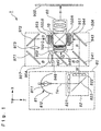
- Fig. 1 schematically shows the configuration of an optical system incorporated in a projection display device 1 of this embodiment.
- the optical system in the projection display device 1 of this embodiment comprises an illumination optical system 80 having a light source 81, a color separation optical system 924 for separating a light beam W emitted from the illumination optical system 80 into a red beam R, a green beam G, and a blue beam B, three liquid crystal light valves 100R, 100G, and 100B for modulating the color beams R, G, and B, a dichroic prism 10 serving as a color synthesizing system for synthesizing the modulated color beams, a projection optical system 60 for enlarging and projecting the synthesized beams onto the surface of a screen 900, and a light guide system 927 for guiding the blue beam B of the color beams R, G, and B to the corresponding liquid crystal light valve 100B.
- the illumination optical system 80 comprises the light source 81, and a uniform illumination optical system 82 for splitting a light beam from the light source 81 into a plurality of partial beams, and superimposing those partial beams onto the liquid crystal light valves 100R, 100G, and 100B.
- the light source 81 includes a light-source lamp 811, such as a halogen lamp, a metal halide lamp, or a xenon lamp, and a reflector 812 for emitting emergent light from the light-source lamp 811 as nearly parallel light.
- a reflector 812 a reflector having a reflecting surface, whose shape is parabolic, elliptic, or the like, is used.
- the uniform illumination optical system 82 includes a first lens plate 821 and a second lens plate 822 that have a plurality of rectangular lenses.
- the uniform illumination optical system 82 also includes a reflecting mirror 823 so as to perpendicularly bend an optical axis 1a of emergent light from the first lens plate 821 toward the front of the device.
- the first and second lens plates 821 and 822 are arranged so as to be at right angles to each other across the reflecting mirror 823.
- Emergent light from the light source 81 is split into a plurality of intermediate beams by the rectangular lenses that constitute the first lens plate 821, and superimposed onto the liquid crystal light valves 100R, 100G, and 100B via the rectangular lenses that constitute the second lens plate 822.
- the liquid crystal light valves 100R, 100G, and 100B are illuminated using the uniform illumination optical system 82 in the projection display device 1 of this embodiment, they can be irradiated with uniform illumination light, which is effective in obtaining a high-contrast projection image.
- the color separation optical system 924 includes a blue and green reflecting dichroic mirror 941, a green reflecting dichroic mirror 942, and a reflecting mirror 943.
- a blue beam B and a green beam G contained in a light beam W are reflected nearly perpendicularly by the blue and green reflecting dichroic mirror 941, and travel toward the green reflecting dichroic mirror 942.
- a red beam R passes through this blue and green reflecting dichroic mirror 941, is reflected nearly perpendicularly by the reflecting mirror 943 disposed behind, and is emitted from an emergent portion 944 for the red beam R toward the dichroic prism 10.
- the green beam G of the blue and green beams B and G which have been reflected by the blue and green reflecting dichroic mirror 941
- the blue beam B passed through the green reflecting dichroic mirror 942 is emitted from an emergent portion 946 for the blue beam B toward the light guide system 927.
- the distances from an emergent portion of the illumination optical system 80 for the light beam W to the emergent portions 944, 945, and 946 of the color separation optical system 924 for the color beams are set to be substantially equal.
- the red beam R and the green beam G thus collimated enter the liquid crystal light valves 100R and 100G, where they are modulated and given corresponding image information. That is to say, these liquid crystal light valves are subjected to switching control by a driving means, which is not shown, according to cage information, and thereby, the color beams passing therethrough are modulated.
- a driving means a known means can be used unaltered.
- the blue beam B is guided to the corresponding liquid crystal light valve 100B via the light guide system 927, where it is similarly modulated according to image information.
- the light guide system 927 comprises a light-collecting lens 954 disposed on the emergent side of the emergent portion 946 for the blue beam B, an incident-side reflecting mirror 971, an emergent-side reflecting mirror 972, an intermediate lens 973 interposed between these reflecting mirrors, and a light-collecting lens 953 disposed in front of the liquid crystal light valve 100B.
- the blue beam B has the longest one of the optical path lengths of the color beams, that is, the distances from the light source 81 to the liquid crystal light valves. Therefore, this light beam undergoes the largest light loss. The light loss can, however, be reduced by interposing the light guide system 927.
- dichroic prism 10 dichroic layers are formed in the shape of an X along bonded surfaces between four right-angle prisms.
- a color image synthesized by the dichroic prism 10 is enlarged and projected onto the surface of the screen 900 at a predetermined position via the projection optical system 60 that is a constituent of a projection lens unit.
- a telecentric lens may be used as the projection optical system 60.
- Fig. 2 shows an equivalent optical system for a red beam, from which the color separation optical system 925, the light-collecting lens 951, and the dichroic prism 10 described above are left out. Furthermore, equivalent optical systems for a green beam and a blue beam are similar, and therefore, descriptions thereof are omitted.
- the liquid crystal light valve 100R is provided, on its light incident side, with a microlens array 102 composed of a plurality of microlenses 101 in order to prevent light utilization efficiency from being deteriorated due to the increase in definition.
- the microlenses 101 are formed corresponding to pixel apertures, and given optical properties such as to collect light incident on the liquid crystal light valve 100R to the corresponding pixel apertures.
- emergent light from the liquid crystal light valve 100R is diffused by the action of the microlenses 101, as shown by solid lines in Fig. 2. For this reason, the emergent light from the liquid crystal light valve 100R spreads wider than emergent light (shown by broken lines in Fig. 2) from a liquid crystal light valve in a projection display device having a conventional configuration.
- the f-number F P of the projection optical system 60 is set to be less than the f-number F L of the illumination optical system so that emergent light from the liquid crystal light valve 100R, which is diffused by the microlenses 101, is efficiently drawn into the projection optical system 60.
- the projection optical system 60A is, in general, frequently represented by a single lens element in most cases, as shown in Fig. 2, it is composed of a plurality of lens elements in normal cases. This means that a plurality of lens elements can be replaced by a single lens element having a function equivalent to that of those lens elements. It is assumed that the f-number F P of the projection optical system refers to the f-number of the single lens element thus replaced, that is to say, a value 1 P /d P that is obtained by dividing a focal distance 1 P of the single lens element by a diameter d P of the lens.
- the f-number F L of the illumination optical system refers to the f-number of a lens element that is disposed on the most downstream side of the optical path, that is, closest to the liquid crystal light valves 100R, 100G, and 100B, among a plurality of lens elements included in the illumination optical system.
- the f-number F L does not refers to the f-number of each lens, but to a value 1 L /d L obtained by dividing a distance 1 L from the lens array to an object to be illuminated by the maximum diameter d L of the lens array (e.g., the diameter in the case of a circular lens array, the length of the diagonal line in the case of a rectangular lens array).
- the f-number F L of the illumination optical system is the f-number of the second lens plate 822, that is, a value 1 L /d L obtained by dividing a distance 1 L from the lens plate 822 to the liquid crystal light valve 100R by the maximum diameter d L of the lens plate 822 (e.g., the diameter in the case of a circular lens plate, the length of the diagonal line in the case of a rectangular lens plate).
- a certain liquid crystal light valve 100B among the liquid crystal light valves 100R, 100G, and 100B, which are objects to be illuminated is frequently positioned farther from the illumination optical system 80 than the other liquid crystal light valves. It is assumed, in such a case, that the distance 1 L from the lens array to an object to be illuminated means the distance to the object to be illuminated, which is nearer positioned.
- the light-collecting lens 954, which is disposed at nearly the same position as those of the liquid crystal light valves 100R and 100G, may be regarded as an object to be illuminated.
- the entire optical system for radiating light onto the liquid crystal light valves 100R, 100G, and 100B serving as illumination areas, that is, the optical path to the liquid crystal light valves 100R, 100G, and 100B, and the optical system existing on the optical path can be called an illumination optical system in a broad sense.
- the color separation optical system 924, the light guide system 927, the light-collecting lens 951 and 952, and the like shown in Fig. 1 are included in the illumination optical system in a broad sense.
- the illumination optical system 80 in a narrow sense however, mainly serves to radiate light onto the liquid crystal light valves 100R, 100G, and 100B.
- the present invention covers such an illumination optical system 80 in a narrow sense.
- the f-number F P of the projection optical system 60, the f-number F L of the illumination optical system, and the f-number F M of the microlens 101 provided in the liquid crystal light valve 100R have the following relationship in this embodiment.
- the f-number F M of the microlens 101 refers to a value obtained by dividing the focal distance of each microlens 101 by the diameter thereof.
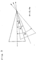
- Fig. 3 shows the relationship among the f-numbers of the illumination optical system 80, the projection optical system 60, and the microlens 101.
- a light beam guided to the projection optical system 60 is a diffused beam from the illumination optical system 80 that is also diffused by the microlens 101.
- the f-number of the projection optical system 60 is set to satisfy the equation (4) by increasing the entrance pupil of the projection optical system 60 so that all light beams having the angle ⁇ P are drawn into the projection optical system 60.
- the f-number F P of the projection optical system, the f-number F L of the illumination optical system, and the f-number F L of the microlens in the projection display device of this embodiment are set to satisfy the equation (5): F P ⁇ [tan ⁇ tan -1 (2 ⁇ F M ) + tan -1 (2 ⁇ F L ) - 90° ⁇ ]/2
- the f-number F P of the projection optical system 60 is set to be less than approximately 1.4.
- the f-number F P of the projection optical system 60 is set to be less than approximately 2.0.
- the f-number F P of the projection optical system 60 is specified in the projection display device 1 of this embodiment so that emergent light from the liquid crystal light valves 100R, 100G, and 100B diffused by the microlenses 101 is efficiently drawn into the projection optical system. For this reason, it is possible to avoid a situation in which a part of emergent light from the liquid crystal light valves 100R, 100G, and 100B with microlenses misses the projection optical system 60, and to thereby prevent light utilization efficiency from being lowered due to diffusion by the microlenses 101.
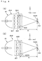
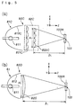
- illumination optical system 80 may be replaced by illumination optical systems 80A to 80D shown in Fig. 4(a), Fig. 4(b), Fig. 5(a), and Fig. 5(b).
- illumination optical systems 80A to 80D shown in Fig. 4(a), Fig. 4(b), Fig. 5(a), and Fig. 5(b).
- similar constituents to those in the illumination optical system 80 are given the same numerals, and a detailed description thereof is omitted.
- the illumination optical system 80A shown in Fig. 4(a) comprises a uniform illumination optical system 82A including two lens plates 821 and 822 and a superimposing lens 824, and a light source 81. While intermediate beams split by the first lens plate 821 are superimposed on the liquid crystal light valves 100R, 100G, and 100B by the second lens plate 822 in the above-described illumination optical system 80A, they are superimposed via the superimposing lens 824 in this modification.
- the f-number F L of the illumination optical system means the f-number of the superimposing lens 824 that is disposed on the most downstream side of the optical path.
- the f-number F L of the illumination optical system is represented by a value 1 L /d L obtained by dividing a distance 1 L from the lens plate 822B, which is disposed on the most downstream side of the optical path, to an object to be illuminated by the maximum diameter d L of the lens plate 822B (e.g., the diameter in the case of a circular lens plate, the length of the diagonal line in the case of a rectangular lens plate).
- the illumination optical system 80C shown in Fig. 5(a) comprises a uniform illumination optical system 82C including two lens plates 821C, and a light source 81C.
- the light source 81C includes a light-source lamp 811 and an elliptic reflector 812C.
- the light source 81C in this modification emits convergent light, as distinct from the above-described light source 81 that emits parallel light.
- the lens plates 821C and 822C that constitute the uniform illumination optical system 82C are shaped in accordance with the width of convergent light emitted from the light source 81C.
- the functions of the lens plates 821C and 822C are similar to those of the lens plates 821 and 822 in the illumination optical system 80.
- the f-number F L of the illumination optical system is represented by a value 1 L /d L obtained by dividing a distance 1 L from the lens plate 822, which is disposed on the most downstream side of the optical path, to an object to be illuminated by the maximum diameter d L of the lens plate 822 (e.g., the diameter in the case of a circular lens plate, the length of the diagonal line in the case of a rectangular lens plate).
- the illumination optical system 80D shown in Fig. 5(b) comprises a light source 81, and a light-collecting lens 825.
- the light-collecting lens 825 serves to prevent light emitted from the light source 81 from diffusing.
- the f-number F L of the illumination optical system means the f-number of the light-collecting lens 825 that is disposed on the most downstream side of the optical path.
- projection display device 1 is a front projection display device that performs projection from the side where a projection plane is observed
- the present invention may also be applied to a rear projection display device that performs projection from the side opposite to the side where a projection plane is observed.
Landscapes
- Physics & Mathematics (AREA)
- Engineering & Computer Science (AREA)
- Multimedia (AREA)
- Signal Processing (AREA)
- General Physics & Mathematics (AREA)
- Optics & Photonics (AREA)
- Chemical & Material Sciences (AREA)
- Crystallography & Structural Chemistry (AREA)
- Projection Apparatus (AREA)
- Liquid Crystal (AREA)
- Devices For Indicating Variable Information By Combining Individual Elements (AREA)
Applications Claiming Priority (3)
| Application Number | Priority Date | Filing Date | Title |
|---|---|---|---|
| JP27784997 | 1997-10-09 | ||
| JP27784997 | 1997-10-09 | ||
| PCT/JP1998/004569 WO1999019759A1 (en) | 1997-10-09 | 1998-10-09 | Projection type display |
Publications (2)
| Publication Number | Publication Date |
|---|---|
| EP0952473A1 true EP0952473A1 (de) | 1999-10-27 |
| EP0952473A4 EP0952473A4 (de) | 2001-08-29 |
Family
ID=17589138
Family Applications (1)
| Application Number | Title | Priority Date | Filing Date |
|---|---|---|---|
| EP98947806A Ceased EP0952473A4 (de) | 1997-10-09 | 1998-10-09 | Projektionsanzeigevorrichtung |
Country Status (10)
| Country | Link |
|---|---|
| US (1) | US6315417B1 (de) |
| EP (1) | EP0952473A4 (de) |
| KR (1) | KR100489459B1 (de) |
| CN (1) | CN100374902C (de) |
| AU (1) | AU742357C (de) |
| BR (1) | BR9806312A (de) |
| CA (1) | CA2264954C (de) |
| RU (1) | RU2199144C2 (de) |
| TW (1) | TW408229B (de) |
| WO (1) | WO1999019759A1 (de) |
Cited By (1)
| Publication number | Priority date | Publication date | Assignee | Title |
|---|---|---|---|---|
| DE19844581A1 (de) * | 1998-09-29 | 2000-04-20 | Manfred Ludewig | Vorrichtung zum elementweisen Steuern der Lichtintensität |
Families Citing this family (16)
| Publication number | Priority date | Publication date | Assignee | Title |
|---|---|---|---|---|
| JP2002350823A (ja) * | 2001-05-28 | 2002-12-04 | Sony Corp | 液晶表示素子および投射型液晶表示装置 |
| JP2003241304A (ja) * | 2002-02-14 | 2003-08-27 | Seiko Epson Corp | プロジェクタ |
| JP4144384B2 (ja) * | 2003-03-11 | 2008-09-03 | セイコーエプソン株式会社 | プロジェクタ |
| RU2262725C2 (ru) * | 2003-04-16 | 2005-10-20 | Научно-учебный комплекс "Радиоэлектроники, лазерной и медицинской техники" Московского государственного технического университета им. Н.Э. Баумана | Проекционная оптическая система для домашнего кинотеатра |
| KR100965877B1 (ko) * | 2003-06-13 | 2010-06-24 | 삼성전자주식회사 | 고효율 프로젝션 시스템 및 칼라화상 형성방법 |
| EA008119B1 (ru) * | 2005-02-07 | 2007-04-27 | Араик Дангян | Способ формирования цветного видеоизображения для проекционных систем с одной электронно-лучевой трубкой |
| RU2297658C1 (ru) * | 2005-11-29 | 2007-04-20 | Самсунг Электроникс Ко., Лтд. | Проекционный дисплей |
| US7486854B2 (en) | 2006-01-24 | 2009-02-03 | Uni-Pixel Displays, Inc. | Optical microstructures for light extraction and control |
| US7920214B2 (en) | 2006-01-25 | 2011-04-05 | Arayik Danghyan | Method for formation of a color video image for projection systems with one cathode ray tube |
| KR101333030B1 (ko) * | 2006-02-22 | 2013-11-26 | 코닌클리케 필립스 엔.브이. | 공간 광 변조 및 광원 변조를 이용한 컬러 이미지 투사 방법 |
| US7766490B2 (en) * | 2006-12-13 | 2010-08-03 | Philips Lumileds Lighting Company, Llc | Multi-color primary light generation in a projection system using LEDs |
| TWI355520B (en) * | 2008-08-21 | 2012-01-01 | All Real Technology Co Ltd | Artificial light source generator |
| CN102116932B (zh) * | 2011-03-08 | 2012-12-26 | 广东威创视讯科技股份有限公司 | 光学图像放大装置和图像显示系统 |
| JP6318670B2 (ja) * | 2014-02-10 | 2018-05-09 | セイコーエプソン株式会社 | プロジェクター |
| CN106953999A (zh) * | 2017-04-17 | 2017-07-14 | 苏州佳世达电通有限公司 | 扫描装置 |
| CN114228608A (zh) * | 2021-12-17 | 2022-03-25 | 一汽奔腾轿车有限公司 | 一种基于微透镜阵列的礼让行人光毯系统及其控制方法 |
Family Cites Families (13)
| Publication number | Priority date | Publication date | Assignee | Title |
|---|---|---|---|---|
| NL8901077A (nl) * | 1989-04-28 | 1990-11-16 | Koninkl Philips Electronics Nv | Optische belichtingsstelsel en projectie-apparaat voorzien van een dergelijk stelsel. |
| JP2815910B2 (ja) * | 1989-07-19 | 1998-10-27 | シャープ株式会社 | 投影形画像表示装置 |
| US5130850A (en) * | 1989-12-20 | 1992-07-14 | Mitsubishi Denki Kabushiki Kaisha | Projection lens system |
| JPH0749479Y2 (ja) * | 1990-07-06 | 1995-11-13 | 日立造船株式会社 | 中性子ラジオグラフィ装置における撮影用カセッテ交換装置 |
| JP2973750B2 (ja) * | 1992-03-31 | 1999-11-08 | 松下電器産業株式会社 | 照明光学装置とそれを用いた投写型表示装置 |
| JPH0749479A (ja) | 1993-06-04 | 1995-02-21 | Matsushita Electric Ind Co Ltd | ライトバルブ投写装置 |
| TW374864B (en) * | 1994-10-28 | 1999-11-21 | Toshiba Corp | Projecting type displaying device and photo-modulating elements array used therein |
| EP0726681B1 (de) * | 1995-02-10 | 2003-04-23 | Sharp Kabushiki Kaisha | Projektionsbildanzeigevorrichtung |
| US6005644A (en) * | 1995-03-08 | 1999-12-21 | Seiko Epson Corporation | Projection display employing circular polarized light for reflection reduction |
| JPH0954279A (ja) | 1995-08-11 | 1997-02-25 | Sanyo Electric Co Ltd | 投写装置 |
| TW374857B (en) * | 1996-06-19 | 1999-11-21 | Toshiba Corp | Display device, liquid crystal display panel, and a projection type display using a liquid crystal display panel |
| JP3473335B2 (ja) * | 1996-08-19 | 2003-12-02 | セイコーエプソン株式会社 | 投写型表示装置 |
| JPH09171150A (ja) | 1997-01-22 | 1997-06-30 | Matsushita Electric Ind Co Ltd | 照明光学装置とそれを用いた投写型表示装置 |
-
1998
- 1998-10-09 CA CA002264954A patent/CA2264954C/en not_active Expired - Fee Related
- 1998-10-09 RU RU99112194/28A patent/RU2199144C2/ru not_active IP Right Cessation
- 1998-10-09 US US09/319,534 patent/US6315417B1/en not_active Expired - Lifetime
- 1998-10-09 EP EP98947806A patent/EP0952473A4/de not_active Ceased
- 1998-10-09 WO PCT/JP1998/004569 patent/WO1999019759A1/ja not_active Ceased
- 1998-10-09 KR KR10-1999-7004084A patent/KR100489459B1/ko not_active Expired - Fee Related
- 1998-10-09 BR BR9806312-0A patent/BR9806312A/pt not_active Application Discontinuation
- 1998-10-09 TW TW087116828A patent/TW408229B/zh not_active IP Right Cessation
- 1998-10-09 AU AU95166/98A patent/AU742357C/en not_active Ceased
- 1998-10-09 CN CNB988014947A patent/CN100374902C/zh not_active Expired - Fee Related
Cited By (1)
| Publication number | Priority date | Publication date | Assignee | Title |
|---|---|---|---|---|
| DE19844581A1 (de) * | 1998-09-29 | 2000-04-20 | Manfred Ludewig | Vorrichtung zum elementweisen Steuern der Lichtintensität |
Also Published As
| Publication number | Publication date |
|---|---|
| AU742357C (en) | 2002-09-19 |
| WO1999019759A1 (en) | 1999-04-22 |
| AU742357B2 (en) | 2002-01-03 |
| BR9806312A (pt) | 2000-03-14 |
| CA2264954C (en) | 2003-01-21 |
| KR100489459B1 (ko) | 2005-05-16 |
| EP0952473A4 (de) | 2001-08-29 |
| RU2199144C2 (ru) | 2003-02-20 |
| AU9516698A (en) | 1999-05-03 |
| CN1241263A (zh) | 2000-01-12 |
| TW408229B (en) | 2000-10-11 |
| CA2264954A1 (en) | 1999-04-22 |
| CN100374902C (zh) | 2008-03-12 |
| US6315417B1 (en) | 2001-11-13 |
| KR20000068929A (ko) | 2000-11-25 |
Similar Documents
| Publication | Publication Date | Title |
|---|---|---|
| US6151166A (en) | Color separation element and image display device using same | |
| US6315417B1 (en) | Projector | |
| USRE39243E1 (en) | Optical element, polarization illumination device, and projector | |
| JP3347676B2 (ja) | 照明装置およびそれを用いた投射型表示装置 | |
| EP1061408A1 (de) | Beleuchtungsanordnung und projektionsanzeige | |
| US6831707B2 (en) | Liquid crystal display element and projection type liquid crystal display device | |
| US6607280B2 (en) | Projection apparatus | |
| EP1211901A2 (de) | Aperturelement zur Verwendung in Videoprojektoren und Videoprojektor, versehen mit diesem Element | |
| USRE38740E1 (en) | Dichroic prism and projection display apparatus | |
| US6188529B1 (en) | Projecting apparatus for a high-resolution color liquid crystal projector | |
| US6796662B2 (en) | Illumination optical system and projector | |
| KR19980081503A (ko) | 배면 투사형 디스플레이 장치 및 스크린 유닛 | |
| US6176585B1 (en) | Projection apparatus | |
| JP2000147500A (ja) | 画像プロジェクタ | |
| JP4074389B2 (ja) | 液晶装置および投写型表示装置 | |
| HK1022951A (en) | Projection type display | |
| AU764831B2 (en) | Projection display device | |
| JP3620303B2 (ja) | 背面投写型表示装置 | |
| KR100930238B1 (ko) | 조명 장치 및 소형 프로젝션 시스템 | |
| JP2768345B2 (ja) | 液晶プロジェクタ | |
| JP2001103400A (ja) | 投射型表示装置 | |
| JP2005099869A (ja) | 投写型表示装置 | |
| JP4007407B2 (ja) | フレネルレンズシート | |
| JPWO1999019759A1 (ja) | 投写型表示装置 | |
| KR20000031113A (ko) | 3판식 디지털 마이크로 미러 프로젝터 광학계 |
Legal Events
| Date | Code | Title | Description |
|---|---|---|---|
| PUAI | Public reference made under article 153(3) epc to a published international application that has entered the european phase |
Free format text: ORIGINAL CODE: 0009012 |
|
| AK | Designated contracting states |
Kind code of ref document: A1 Designated state(s): DE FR GB |
|
| 17P | Request for examination filed |
Effective date: 19990922 |
|
| A4 | Supplementary search report drawn up and despatched |
Effective date: 20010717 |
|
| AK | Designated contracting states |
Kind code of ref document: A4 Designated state(s): DE FR GB |
|
| RIC1 | Information provided on ipc code assigned before grant |
Free format text: 7G 02B 27/18 A, 7H 04N 5/74 B, 7G 02B 27/00 B |
|
| 17Q | First examination report despatched |
Effective date: 20040521 |
|
| STAA | Information on the status of an ep patent application or granted ep patent |
Free format text: STATUS: THE APPLICATION HAS BEEN REFUSED |
|
| 18R | Application refused |
Effective date: 20060709 |
|
| REG | Reference to a national code |
Ref country code: HK Ref legal event code: WD Ref document number: 1022951 Country of ref document: HK |