EP0952521B1 - Verfahren zum Verfolgen von Konfigurationsänderungen in Netzwerken von Rechnersystemen durch historische Überwachung des Konfigurationsstatus der Vorrichtungen im Netzwerk - Google Patents
Verfahren zum Verfolgen von Konfigurationsänderungen in Netzwerken von Rechnersystemen durch historische Überwachung des Konfigurationsstatus der Vorrichtungen im Netzwerk Download PDFInfo
- Publication number
- EP0952521B1 EP0952521B1 EP99303004A EP99303004A EP0952521B1 EP 0952521 B1 EP0952521 B1 EP 0952521B1 EP 99303004 A EP99303004 A EP 99303004A EP 99303004 A EP99303004 A EP 99303004A EP 0952521 B1 EP0952521 B1 EP 0952521B1
- Authority
- EP
- European Patent Office
- Prior art keywords
- stored
- support node
- remote support
- configuration data
- time stamp
- Prior art date
- Legal status (The legal status is an assumption and is not a legal conclusion. Google has not performed a legal analysis and makes no representation as to the accuracy of the status listed.)
- Expired - Lifetime
Links
Images


Classifications
-
- G—PHYSICS
- G06—COMPUTING OR CALCULATING; COUNTING
- G06F—ELECTRIC DIGITAL DATA PROCESSING
- G06F11/00—Error detection; Error correction; Monitoring
- G06F11/30—Monitoring
- G06F11/3051—Monitoring arrangements for monitoring the configuration of the computing system or of the computing system component, e.g. monitoring the presence of processing resources, peripherals, I/O links, software programs
-
- G—PHYSICS
- G06—COMPUTING OR CALCULATING; COUNTING
- G06F—ELECTRIC DIGITAL DATA PROCESSING
- G06F11/00—Error detection; Error correction; Monitoring
- G06F11/07—Responding to the occurrence of a fault, e.g. fault tolerance
- G06F11/0703—Error or fault processing not based on redundancy, i.e. by taking additional measures to deal with the error or fault not making use of redundancy in operation, in hardware, or in data representation
- G06F11/0706—Error or fault processing not based on redundancy, i.e. by taking additional measures to deal with the error or fault not making use of redundancy in operation, in hardware, or in data representation the processing taking place on a specific hardware platform or in a specific software environment
- G06F11/0709—Error or fault processing not based on redundancy, i.e. by taking additional measures to deal with the error or fault not making use of redundancy in operation, in hardware, or in data representation the processing taking place on a specific hardware platform or in a specific software environment in a distributed system consisting of a plurality of standalone computer nodes, e.g. clusters, client-server systems
-
- G—PHYSICS
- G06—COMPUTING OR CALCULATING; COUNTING
- G06F—ELECTRIC DIGITAL DATA PROCESSING
- G06F11/00—Error detection; Error correction; Monitoring
- G06F11/22—Detection or location of defective computer hardware by testing during standby operation or during idle time, e.g. start-up testing
- G06F11/2289—Detection or location of defective computer hardware by testing during standby operation or during idle time, e.g. start-up testing by configuration test
-
- G—PHYSICS
- G06—COMPUTING OR CALCULATING; COUNTING
- G06F—ELECTRIC DIGITAL DATA PROCESSING
- G06F11/00—Error detection; Error correction; Monitoring
- G06F11/30—Monitoring
- G06F11/3003—Monitoring arrangements specially adapted to the computing system or computing system component being monitored
- G06F11/3006—Monitoring arrangements specially adapted to the computing system or computing system component being monitored where the computing system is distributed, e.g. networked systems, clusters, multiprocessor systems
-
- G—PHYSICS
- G06—COMPUTING OR CALCULATING; COUNTING
- G06F—ELECTRIC DIGITAL DATA PROCESSING
- G06F11/00—Error detection; Error correction; Monitoring
- G06F11/30—Monitoring
- G06F11/34—Recording or statistical evaluation of computer activity, e.g. of down time, of input/output operation ; Recording or statistical evaluation of user activity, e.g. usability assessment
- G06F11/3466—Performance evaluation by tracing or monitoring
- G06F11/3495—Performance evaluation by tracing or monitoring for systems
-
- H—ELECTRICITY
- H04—ELECTRIC COMMUNICATION TECHNIQUE
- H04L—TRANSMISSION OF DIGITAL INFORMATION, e.g. TELEGRAPHIC COMMUNICATION
- H04L41/00—Arrangements for maintenance, administration or management of data switching networks, e.g. of packet switching networks
- H04L41/02—Standardisation; Integration
- H04L41/0246—Exchanging or transporting network management information using the Internet; Embedding network management web servers in network elements; Web-services-based protocols
- H04L41/0253—Exchanging or transporting network management information using the Internet; Embedding network management web servers in network elements; Web-services-based protocols using browsers or web-pages for accessing management information
-
- H—ELECTRICITY
- H04—ELECTRIC COMMUNICATION TECHNIQUE
- H04L—TRANSMISSION OF DIGITAL INFORMATION, e.g. TELEGRAPHIC COMMUNICATION
- H04L41/00—Arrangements for maintenance, administration or management of data switching networks, e.g. of packet switching networks
- H04L41/08—Configuration management of networks or network elements
- H04L41/0803—Configuration setting
- H04L41/084—Configuration by using pre-existing information, e.g. using templates or copying from other elements
- H04L41/0843—Configuration by using pre-existing information, e.g. using templates or copying from other elements based on generic templates
-
- H—ELECTRICITY
- H04—ELECTRIC COMMUNICATION TECHNIQUE
- H04L—TRANSMISSION OF DIGITAL INFORMATION, e.g. TELEGRAPHIC COMMUNICATION
- H04L41/00—Arrangements for maintenance, administration or management of data switching networks, e.g. of packet switching networks
- H04L41/08—Configuration management of networks or network elements
- H04L41/085—Retrieval of network configuration; Tracking network configuration history
- H04L41/0853—Retrieval of network configuration; Tracking network configuration history by actively collecting configuration information or by backing up configuration information
-
- H—ELECTRICITY
- H04—ELECTRIC COMMUNICATION TECHNIQUE
- H04L—TRANSMISSION OF DIGITAL INFORMATION, e.g. TELEGRAPHIC COMMUNICATION
- H04L41/00—Arrangements for maintenance, administration or management of data switching networks, e.g. of packet switching networks
- H04L41/08—Configuration management of networks or network elements
- H04L41/085—Retrieval of network configuration; Tracking network configuration history
- H04L41/0859—Retrieval of network configuration; Tracking network configuration history by keeping history of different configuration generations or by rolling back to previous configuration versions
-
- H—ELECTRICITY
- H04—ELECTRIC COMMUNICATION TECHNIQUE
- H04L—TRANSMISSION OF DIGITAL INFORMATION, e.g. TELEGRAPHIC COMMUNICATION
- H04L41/00—Arrangements for maintenance, administration or management of data switching networks, e.g. of packet switching networks
- H04L41/08—Configuration management of networks or network elements
- H04L41/0866—Checking the configuration
- H04L41/0869—Validating the configuration within one network element
-
- H—ELECTRICITY
- H04—ELECTRIC COMMUNICATION TECHNIQUE
- H04L—TRANSMISSION OF DIGITAL INFORMATION, e.g. TELEGRAPHIC COMMUNICATION
- H04L43/00—Arrangements for monitoring or testing data switching networks
- H04L43/08—Monitoring or testing based on specific metrics, e.g. QoS, energy consumption or environmental parameters
- H04L43/0805—Monitoring or testing based on specific metrics, e.g. QoS, energy consumption or environmental parameters by checking availability
- H04L43/0817—Monitoring or testing based on specific metrics, e.g. QoS, energy consumption or environmental parameters by checking availability by checking functioning
-
- G—PHYSICS
- G06—COMPUTING OR CALCULATING; COUNTING
- G06F—ELECTRIC DIGITAL DATA PROCESSING
- G06F11/00—Error detection; Error correction; Monitoring
- G06F11/07—Responding to the occurrence of a fault, e.g. fault tolerance
- G06F11/0703—Error or fault processing not based on redundancy, i.e. by taking additional measures to deal with the error or fault not making use of redundancy in operation, in hardware, or in data representation
- G06F11/079—Root cause analysis, i.e. error or fault diagnosis
-
- G—PHYSICS
- G06—COMPUTING OR CALCULATING; COUNTING
- G06F—ELECTRIC DIGITAL DATA PROCESSING
- G06F11/00—Error detection; Error correction; Monitoring
- G06F11/22—Detection or location of defective computer hardware by testing during standby operation or during idle time, e.g. start-up testing
- G06F11/2294—Detection or location of defective computer hardware by testing during standby operation or during idle time, e.g. start-up testing by remote test
-
- G—PHYSICS
- G06—COMPUTING OR CALCULATING; COUNTING
- G06F—ELECTRIC DIGITAL DATA PROCESSING
- G06F11/00—Error detection; Error correction; Monitoring
- G06F11/30—Monitoring
- G06F11/32—Monitoring with visual or acoustical indication of the functioning of the machine
- G06F11/324—Display of status information
- G06F11/327—Alarm or error message display
-
- G—PHYSICS
- G06—COMPUTING OR CALCULATING; COUNTING
- G06F—ELECTRIC DIGITAL DATA PROCESSING
- G06F2201/00—Indexing scheme relating to error detection, to error correction, and to monitoring
- G06F2201/835—Timestamp
-
- G—PHYSICS
- G06—COMPUTING OR CALCULATING; COUNTING
- G06F—ELECTRIC DIGITAL DATA PROCESSING
- G06F2201/00—Indexing scheme relating to error detection, to error correction, and to monitoring
- G06F2201/875—Monitoring of systems including the internet
-
- H—ELECTRICITY
- H04—ELECTRIC COMMUNICATION TECHNIQUE
- H04L—TRANSMISSION OF DIGITAL INFORMATION, e.g. TELEGRAPHIC COMMUNICATION
- H04L43/00—Arrangements for monitoring or testing data switching networks
- H04L43/04—Processing captured monitoring data, e.g. for logfile generation
- H04L43/045—Processing captured monitoring data, e.g. for logfile generation for graphical visualisation of monitoring data
-
- H—ELECTRICITY
- H04—ELECTRIC COMMUNICATION TECHNIQUE
- H04L—TRANSMISSION OF DIGITAL INFORMATION, e.g. TELEGRAPHIC COMMUNICATION
- H04L43/00—Arrangements for monitoring or testing data switching networks
- H04L43/06—Generation of reports
- H04L43/067—Generation of reports using time frame reporting
-
- H—ELECTRICITY
- H04—ELECTRIC COMMUNICATION TECHNIQUE
- H04L—TRANSMISSION OF DIGITAL INFORMATION, e.g. TELEGRAPHIC COMMUNICATION
- H04L43/00—Arrangements for monitoring or testing data switching networks
- H04L43/10—Active monitoring, e.g. heartbeat, ping or trace-route
- H04L43/106—Active monitoring, e.g. heartbeat, ping or trace-route using time related information in packets, e.g. by adding timestamps
Definitions
- This invention relates to computer systems and more particularly to managing and troubleshooting computer systems and other connected devices within networks. Even more particularly, the invention relates to managing and troubleshooting computer systems within networks by tracking configuration changes through historical monitoring of configuration status of devices on the network.
- Managing and troubleshooting computer system networks is a critical and essential task in most businesses, governmental entities, and educational institutions today.
- Several products have been developed to help assist the system administrator perform management and troubleshooting functions on computers and interconnect devices, such as routers, bridges, hubs, switches, etc., on the network.
- Some products are designed to help manage system configurations on a real time basis. Such products can tell the system administrator what the configurations of particular computers or devices are at the present moment. Some products may also enable the system administrator to make immediate changes to particular computers or devices or restore them to a previous state.
- US-A- 5 696 701 discloses a system and method that tracks configuration changes in a computer system, by comparing at each startup of a monitored computer the configuration with the configuration previously stored on that computer, and transmitting configuration changes to a remote monitoring computer
- Yet another aspect of the invention is to save the configuration status of computers and interconnect devices at particular points in time within a revision control system.
- Still another aspect of the invention is to identify what has changed in the configuration of computers and interconnect devices to aid in troubleshooting and managing a computer system network.
- a further aspect of the invention is to display the configuration status of computers and interconnect devices at particular points in time in the past.
- a still further aspect of the invention is to change the time frames for displaying configuration status of computers and interconnect devices.
- Another aspect of the invention is to organize the configuration data collected into a logical hierarchy.
- a still further aspect of the invention is to display configuration status data collected on computers and interconnect devices on a web browser.
- the above and other aspects of the invention are accomplished in a tracking system that uses a revision control system and configuration information gathering to track and store configuration changes on a historical basis for computers and interconnect devices to aid in managing and troubleshooting networks of computer systems.
- the configuration data of monitored computers and interconnect devices on a network is gathered on a periodic basis and stored in a data storehouse within a separate computer, referred to as a remote support node, which is connected to the network.
- the data storehouse is made up of a data base and the revision control system.
- the configuration information may be displayed on a graphics display of the remote support node directly, but more typically is accessed through another computer, having a web browser, that accesses the remote support node over the network.
- the method collects, among other things, configuration information about the operating system, file system, printing and spooling, boot and shutdown, hardware, software, and network configurations.
- configuration information about interfaces IP addresses, routes, static routes, TCP ports, UDP ports, SNMP variables, human and machine readable configuration files, and installed cards.
- Collector software residing on the remote support node gathers configuration data from monitored client computers and interconnect devices on the network.
- Each configuration item collected from computers and network interconnect devices is specified by a data collection template built into the tracking system. Different templates are available for various computer types and interconnect devices, and each template determines what configuration items can be collected from each particular type of device.
- client collector software All client computers being monitored require special resident software, referred to as client collector software, to help facilitate the secure collection of configuration information.
- client collector software For monitored interconnect devices, no additional software is required, other than the standard SNMP (Simple Network Management Protocol), Telnet (remote login virtual terminal protocol), and TFTP (Trivial File Transfer Protocol) facilities already available within the interconnect devices.
- the collector examines the interconnect device type and the requested configuration item to be collected to determine which of these communications methods, or which combination of them, is most appropriate.
- monitored interconnect devices must grant access to the collection process. Granting this access usually involves making a configuration change to the monitored interconnect device to enable collection.
- the collector software collects configuration items at preset collection cycles, normally once a day, by pre-defining an initial collection time and a frequency, usually daily. Each time a collection occurs, the data base is updated to start the next collection at the last collection time plus the frequency.
- a snapshot is constructed for each configuration item for each monitored computer or interconnect device, and, if a change has occurred, the changes are stored in the data storehouse.
- the configuration item may be a text file or the output of a command which displays configuration information in ASCII format.
- a snapshot is a unit of configuration data as it appears when collected from a monitored device. The actual data collected is stored in the revision control system, while the data base contains information about what has changed and the logical hierarchy of the systems being monitored.
- the graphics display is split into two frames.
- the information's logical hierarchy is displayed in a tree format in one of the frames.
- the changes found between snapshots taken on different collection cycles are displayed in the other frame.
- Different configuration data may be displayed by changing the collection cycles selected for comparison.
- Configuration items which have changed between the two collection cycles selected are indicated by a marker placed on the icon of the item in the tree. If the changed configuration item is in a group in the tree that has not been opened, the marker is propagated up the tree and displayed on the group icon. This notifies the user that at some level below this group icon, a change has occurred in a configuration item.
- the user can eventually display the individual item or items that have changed that have the marker.
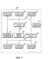
- FIG. 1 shows a block diagram of a networked system of computers and interconnect devices incorporating the tracking system of the present invention.
- computer system network 100 has a remote support node 102 connected to the other components of computer system network 100 through network connections 104.
- Computer system network 100 also has interconnect devices 106, which may be routers, bridges, hubs, switches, etc., also connected through network connections 104 to remote support node 102.
- Computer system network 100 may have more or less than the number of interconnect devices 106 shown in FIG. 1.
- Computer system network 100 also has monitored computers 108 connected through network connections 104 to remote support node 102.
- Computer system network 100 may have more or less than the number of monitored computers 108 shown in FIG. 1.
- Browser computers 110 access remote support node 102 through network connections 104 in order to view configuration data stored on remote support node 102.
- Monitored and browser computer 112 is monitored by remote support node 102 through network connections 104.
- Monitored and browser computer 112 can also access remote support node 102 through network connections 104 in order to view configuration data stored on remote support node 102.
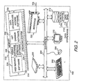
- FIG. 2 shows a block diagram of remote support node 102 (FIG. 1) of the tracking system of the present invention.
- remote support node 102 contains a processing element 202.
- Processing element 202 communicates to other elements of remote support node 102 over a system bus 204.
- a keyboard 206 allows a user to input information into remote support node 102 and a graphics display 210 allows remote support node 102 to output information to the user.
- a mouse 208 is also used to input information.
- Storage device 212 is used to store data and programs within remote support node 102.
- data storehouse 218 which has two components: data base 214 and revision control system 216.
- Communications interface 220 also connected to system bus 204, receives information from network connection 104.
- a memory 222 also attached to system bus 204, contains an operating system 224, web server software 226, pebble software 228, hat daemon software 230, data storehouse access software 232, and schedule software 234 that are called up from storage device 212.
- a browser computer 110 requests a page (html file) of the tracking system of the present invention from remote support node 102.
- the request is handled by web server software 226, which invokes pebble software 228.
- Pebble software 228 is made up of Common Gateway Interface (CGI) scripts.
- CGI Common Gateway Interface
- the CGI script passes a token to hat daemon software 230 to get permission to run. If permission to run is given, then the CGI script accesses data storehouse 218 through data storehouse access software 232, which may be the access software for data base 214, or the access software for revision control system 216, or both.
- the data accessed from data storehouse 218 is passed back to web server software 226, which passes it on to browser computer 110 for display in the browser frames.
- Schedule software 234 is explained in FIG. 6.
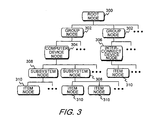
- FIG. 3 shows a block diagram of the hierarchy for storing data of the tracking system of the present invention.
- the configuration data that is collected and stored in data storehouse 218 (FIG. 2) is structured by a view. This view imposes a hierarchical organization on the configuration data collected from the monitored devices of the networked systems. Although the view corresponds closely to how the data is structured in the user interface, it should not be thought of as the display.
- root node 300 which is normally an entity name or a division name of an entity utilizing the tracking system. Examples might be "Acme Company” or "Production Division of Acme Company”. Beneath root node 300, group nodes 302 are organized to track computers and interconnect devices in groups. Typical examples might be “accounting group”, “manufacturing group”, and “research and development group”.
- Computer device nodes 304 list all the computers contained under group nodes 302.
- Interconnect device nodes 306 list all the interconnect devices contained under group nodes 302.
- Computer device nodes 304 may be further broken down into subsystem nodes 308.
- a subsystem node may represent a group of software within the computer, such as "operating system”, "accounting system”, etc.
- item nodes 310 are leaf level nodes representing the individually collected configuration data.
- Item nodes 310 are children of subsystem nodes 308 and interconnect device nodes 306.
- Item nodes 310 may also be direct children of computer device nodes 304 in the absence of a subsystem node 308. Additional group nodes, device nodes, subsystem nodes, and item nodes not shown in FIG. 3 are depicted with the "" notation.
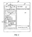
- FIG. 4 shows a representation of a screen capture of a browser computer 110 or a monitored and browser computer 112 accessing the stored data in the tracking system of the present invention.
- screen display 400 of browser computer 110 or monitored and browser computer 112 (FIG. 1) has loaded up web browser software and has requested the URL (Universal Resource Locator) of the tracking system of the present invention.
- Remote support node 102 (FIG. 1) has returned the html page requested for display on screen display 400.
- Screen display 400 is divided into two frames: tracking tree frame 402 and data display frame 404.
- Tabs 406 may be selected in tracking tree frame 402 to access the different functionality of the tracking system. Selecting an administration tab gives the user access to the administrative functions of the present invention to set up the tracking system.
- Users and user accounts may be added or deleted; computers and interconnect devices may be added or deleted; groups may be added or deleted; the collection schedule may be set or changed; and individual items may be enabled or disabled from collection. Selecting a log tab allows the user to access the logging functions of the present invention to view log entries of collection activities, errors, and alarms.
- Selecting a tracking tab gives the user access to the present inventions tracking functions. Selecting the tracking tab gives the user access to tracking tree 412 and available actions 408. By selecting buttons 410 within available actions 408, the user can alter how the stored data is displayed. For example, by selecting different buttons 410, the user can change the collection cycles selected for which tracking tree 412 displays configuration information; show configuration status for a particular collection cycle; show only the changes in configuration status between two particular collection cycles; update the display to reflect current configuration information; or access help files.
- Buttons 410 allow the user to select the beginning and ending collection cycles for displaying changes in configuration information. These two collection cycles selected define the range over which observed configuration changes are reported.
- An observed change is a difference between the two snapshots of the configuration item as captured on the two collection cycles selected.
- the tracking system takes the difference between the two snapshots, if any, calls the difference out for the user, and the difference itself is viewable through the web browser user interface.
- This difference analysis has intelligence in that inconsequential or expected changes, such as dates in command outputs, will be ignored and not flagged as differences. Differences in configuration items that are normally always changing are ignored.
- Tracking tree 412 is an expandable index of configuration items being tracked for each monitored device and is constructed from the data in data base 214. This is done so that when a user logs in to the tracking system and it becomes time to populate tracking tree 412, it will happen very quickly.
- revision control system 216 supplies the data regarding the changes that were made in that data item and displays those changes in data display frame 404.
- Tracking tree 412 utilizes the data hierarchy of FIG. 3 to display configuration information. To view information about groups, devices, and individual configuration items, also referred to as data items, the user may click on the [+] symbols to expand the tree and then select the name of the item of interest.
- change indicators 420 are placed on or next to each icon in the tree in the chain starting with the group node level down to where the change has occurred at the item node level.
- Change indicators 420 may be a mark of any kind or of any color.
- a blue change indicator 420 represents a change
- a yellow change indicator 420 represents a collection failure
- a brown change indicator 420 represents that the configuration item was disabled from collection. If a change has occurred in a configuration item from comparing the two collection cycles selected, and only the group nodes are displayed when tracking tree frame 402 is displayed, a change indicator 420 will be on or next to its group node icon.
- Clicking on the [+] symbol for the group node icon will expand the tree to list all the devices under that group node.
- the device in which change has occurred will have a change indicator 420 on or next to its device icon.
- Clicking on the [+] symbol for the device icon will expand the tree to list all the subsystems, if any, under that device node.
- the subsystem, if any, in which change has occurred will have a change indicator 420 on or next to its subsystem icon.
- Clicking on the [+] symbol for the subsystem icon will expand the tree to list all the data items under that subsystem node.
- the data item in which change has occurred will have a change indicator 420 on or next to its data item icon.
- Selecting a device name in tracking tree 412 displays the name of the data collection template assigned to the device. Selecting individual configuration item names displays information about the item. Right clicking on any name, icon, or symbol in tracking tree 412 accesses a pop-up menu which provides access to appropriate actions. Selecting a Properties option from the pop-up menu displays information about the item selected.
- Time frame 414 displays the dates of the two collection cycles selected for displayed changes. Changes within time frame 416 displays the changes found in data items between the two collection cycles shown in time frame 414.
- Collection history 418 displays the date and time that the data item in question changed.
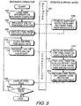
- FIG. 5 shows a flow diagram of displaying stored configuration information located in a remote support node on a browser computer having web browser software.
- web browser software is loaded on browser computer 110 (FIG. 1).
- a user requests the URL of the tracking system of the present invention.
- the web browser software establishes a connection through network connections 104 (FIG. 1) to remote support node 102 (FIG. 1).
- remote support node 102 finds and returns to browser computer 110 through network connections 104 the html page requested in block 502.
- the html page received from block 506 is displayed in screen display 400 (FIG. 4) on browser computer 110.
- the screen display is divided into tracking tree frame 402 (FIG. 4) and data display frame 404 (FIG. 4).
- Tracking tree frame 402 contains applets, which are programs written in a programming language supported by the Web browser. Some applets associated with the html page run automatically when the html page is received and control what is displayed within tracking tree frame 402.
- the user may choose to receive more data in block 510 by clicking on any of several hyperlinks that may be displayed in screen display 400. Additionally, certain buttons, tabs, and data item names, which act like hyperlinks but are really applets, may be clicked on in tracking tree frame 402 to receive more data. Tabs 406, available actions buttons 410, and selecting data item names in tracking tree 412 (FIG. 4) are examples of such applets.
- browser computer 110 After clicking on one of these hyperlinks or applet controlled items, in block 512 browser computer 110 requests the URL associated with the hyperlink, or initiates the applet controlled item.
- the applet controlled items are typically requests for Common Gateway Interface (CGI) scripts.
- CGI Common Gateway Interface
- the request for the URL or the CGI script is sent through network connections 104 and received by remote support node 102 in block 514, where the request for the html page is received, or the requested CGI script is loaded.
- remote support node 102 finds the html page, or the CGI script communicates with hat daemon software 230 (FIG. 2) to get permission to run, if required. If permission is granted or not required, the CGI script runs, fetching data from data storehouse 218 (FIG. 2).
- the html page is returned, or the data fetched from data storehouse 218 is formatted into html format, and then returned through network connections 104 to browser computer 110 for display on screen display 400.
- the html page from either the requested URL or CGI script is normally displayed in data display frame 404, displaying the data requested by the user.
- the CGI script that was run may not return any data for display in data display frame 404. Instead, a message of some kind may be posted to tracking tree frame 402.
- control returns to block 510 where the user may click on a next hyperlink or applet controlled item. If the answer in block 522 is no, then the program ends, leaving the current html page displayed. The user may then select other URL addresses unrelated to the tracking system, or close the web browser software and load other programs.
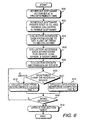
- FIG. 6 shows a flow diagram of a remote support node collecting configuration data from computers and interconnect devices.
- schedule software 234 (FIG. 2) activates at a predetermined time.
- the user will set the activation time to occur once a day when there is low activity anticipated on the network, such as late at night or early in the morning.
- the user may initiate a collection at any time that a scheduled collection is not already in progress. Collections, both scheduled and user initiated, may also be limited in scope to specific groups or devices as opposed to the entire enterprise.
- schedule software 234 passes a collection root identifier to a portion of pebble software 228 (FIG. 2) and invokes that portion of pebble software 228. That portion of pebble software 228 that receives the collection root identifier and is invoked by schedule software 234 is referred to as collector.
- the collection root identifier determines the scope of the collection to be performed.
- collector accesses data storehouse 218 (FIG. 2) and requests the list of items to be collected that fall within the scope of the passed in collection root identifier.
- the list is comprised of Globally Unique Identifiers (GUIDs, or simply "identifiers”.
- GUIDs Globally Unique Identifiers
- Each identifier in the list is associated with a unique configuration item to be collected from the various monitored devices that are included within the scope of the collection root identifier.
- Each configuration item is a unit of data that is collected and monitored by the tracking system, which provides a mapping between the name of a configuration item and the identifier. This data could be a text file or the output of a command which displays configuration information in ASCII format.
- collector will also collect any attributes of the data specified in the data collection template that are useful to the user. Not all configuration data has useful attributes, so not all configuration data items will have attributes associated with them. The attributes that are collected will be displayed to the user.
- a unit of configuration data as it appears when collected from a monitored device is called a snapshot. If a snapshot has changed from the previously collected version of that snapshot, the differences will be stored in data storehouse 218 on remote support node 102.
- the set of all snapshots of a configuration item which have been collected and stored in data storehouse 218 is called a configuration storable.
- collector in block 606 accesses data storehouse 218 and gathers collection method information from data storehouse 218 on each of the identifiers in the list, such as what devices should specific data items be collected from, what commands are to be used for collecting specific data items, and the signature of the last collection of a specific data item.
- the signature may be, for example, a checksum of the previous output, or a last known modified date. Prior to the first collection, the signature for a data item has no value.
- collector then groups the information gathered in block 606 by device.
- Block 610 determines if the first device in the list is a monitored computer or interconnect device. If the first device is a monitored interconnect device, then control passes to block 612, which calls FIG. 7 to perform the data collection process on the monitored interconnect device. If the first device in block 610 is a monitored computer, then control passes to block 614, which calls FIG. 8 to perform the data collection process on the monitored computer.
- block 616 determines if the collection process is to be performed on any more devices. If the answer is yes, control passes to block 610 ,which determines if the next device in the list is a monitored computer or interconnect device. If the answer in block 616 is no, then control passes to block 618, which updates the collection tables in remote support node 102, and then the process ends.
- the collection tables store information regarding the collection, such as the time and date of the collection, the scope of the collection, whether there were any changes in the collection as compared to the previous collection, and if there were any failures.
- FIGS. 7 and 7A show a flow diagram of configuration data collection from a monitored interconnect device.
- collector invokes a collection script within remote support node 102 associated with the first type of monitored interconnect device 106 (FIG. 1).
- the collection script invokes the first collection command.
- Block 704 determines if the command to collect a configuration item was run successfully. There may be a time limit imposed on running the command, or a set number of tries allowed, or both. If the collection command was not run successfully, then in block 706 a time stamp is set and an error message is generated, and both are captured. Block 708 returns the time stamp and the error message to remote support node 102. Block 710 stores the time stamp and error message in a log file in data base 214 within data storehouse 218 (FIG. 2). The data is stored in ASCII format. Control then passes to block 728.
- Block 712 If the collection command was run successfully in block 704, then in block 712 a new signature is created and a time stamp is set. Block 714 then captures the output of the command, any attributes associated with the configuration data to be collected, the new signature, and the time stamp. Block 716 returns this captured data to remote support node 102 and stores it in memory 222. Block 718 compares the new signature for the configuration item from block 712 to the previously collected signature for that same configuration item. Block 720 determines if the two signatures compared in block 718 are the same or different. If there is no difference between the two signatures, then in block 722 the output of the command, any attributes, the new signature, and the time stamp are discarded. Control then passes to block 728.
- Block 720 If in block 720 the two signatures are determined to be different, then in block 724 the differences in the output of the command, any attributes, and the time stamp are stored in revision control system 216 within data storehouse 218 (FIG. 2). Block 726 then stores the new signature, the time stamp, and a change event indicator in data base 214 within data storehouse 218. All of the data is stored in ASCII format. Control then passes to block 728.
- Block 728 determines if there are any more collection commands to be run in the group for this monitored interconnect device 106. If the answer is yes, control passes to block 702 where the next command is invoked. If the answer in block 728 is no, then control returns to FIG. 6.
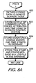
- FIGS. 8 and 8A show a flow diagram of configuration data collection from a monitored computer.
- collector launches a remote execution of the collection process through a DCE (Data Communication Exchange) RPC (Remote Procedure Call) procedure by passing the group of information for the first monitored computer to the first monitored computer.
- DCE Data Communication Exchange
- RPC Remote Procedure Call
- collector invokes the client collection software that has been previously installed on monitored computer 108.
- the client collection software invokes the first passed in collection command.
- Block 806 determines if the command to collect a configuration item was run successfully. There may be a time limit imposed on running the command, or a set number of tries allowed, or both. If the collection command was not run successfully, then in block 808 the client collection software sets a time stamp and generates an error message, and both are stored in a memory in monitored computer 108 (FIG. 1). The data is stored in ASCII format. Control then passes to block 818.
- Block 810 the client collection software creates a new signature for the configuration item and compares this new signature to the previously collected signature that was passed in block 800.
- Block 812 determines if the two signatures compared in block 810 are the same or different. If there is no difference between the two signatures, then in block 814 the output of the command, any attributes, the new signature, and the time stamp are discarded. Control then passes to block 818.
- Block 818 determines if there are any more collection commands to be run in the group for this monitored computer 108. If the answer is yes, control passes to block 804 where the client collection software invokes the next passed in command. If the answer in block 818 is no, then control passes to block 820.
- block 820 the stored data from blocks 808 and 816 is returned to remote support node 102 (FIG. 1).
- the differences in the output of the command, any attributes, and the time stamp for each collection command having a difference are stored in revision control system 216 within data storehouse 218 (FIG. 2).
- Block 824 then stores the new signature, the time stamp, and a change event indicator for each collection command having a difference in data base 214 within data storehouse 218.
- Block 826 stores the time stamp and error message for each collection command that failed in log file in data base 214 within data storehouse 218 (FIG. 2). All of the data is stored in ASCII format. Control then returns to FIG. 6.
Landscapes
- Engineering & Computer Science (AREA)
- Theoretical Computer Science (AREA)
- General Engineering & Computer Science (AREA)
- Signal Processing (AREA)
- Physics & Mathematics (AREA)
- Computer Networks & Wireless Communication (AREA)
- General Physics & Mathematics (AREA)
- Quality & Reliability (AREA)
- Computer Hardware Design (AREA)
- Computing Systems (AREA)
- Mathematical Physics (AREA)
- Environmental & Geological Engineering (AREA)
- Debugging And Monitoring (AREA)
- Computer And Data Communications (AREA)
- Multi Processors (AREA)
- Testing And Monitoring For Control Systems (AREA)
Claims (10)
- Ein computerisiertes Verfahren zum Verfolgen von Konfigurationsveränderungen innerhalb eines Computersystems, das folgende Schritte aufweist:(a) Sammeln (602, 604, 606, 608, 610, 612, 614) eines ersten Schnappschusses von einem Konfigurationsdatenelement mit einem eindeutigen Identifizierer zu einem ersten vorbestimmten Zeitpunkt von einer ersten überwachten Vorrichtung (106, 108) in einem Computersystemnetz (100) und Einstellen eines ersten Zeitstempels, der anzeigt, wann der erste Schnappschuß gesammelt wurde;(b) Speichern (724, 726, 822, 824) des ersten Schnappschusses des Konfigurationsdatenelements und des ersten Zeitstempels in einem Datenlager (218) innerhalb eines entfernten Trägerknotens (102), der mit der ersten überwachten Vorrichtung (106, 108) durch eine erste Netzwerkverbindung (104) innerhalb des Computersystemnetzwerks (100) verbunden ist;(c) Sammeln (602, 604, 606, 608, 610, 612, 614) eines zweiten Schnappschusses des Konfigurationsdatenelements mit dem eindeutigen Identifizierer zu einem zweiten vorbestimmten Zeitpunkt von der ersten überwachten Vorrichtung (106, 108) in dem Computersystemnetz (100) und Einstellen eines zweiten Zeitstempels, der anzeigt, wann der zweite Schnappschuß gesammelt wurde;(d) Vergleichen (718, 810) des gespeicherten ersten Schnappschusses des Konfigurationsdatenelements mit dem gesammelten zweiten Schnappschuß des Konfigurationsdatenelements;(e) wenn Schritt (d) bestimmt, daß der gesammelte zweite Schnappschuß des Konfigurationsdatenelements zumindest einen Unterschied (720, 812) von dem gespeicherten ersten Schnappschuß des Konfigurationsdatenelements aufweist, Ausführen von Schritt (f) und nicht von Schritt (g), und wenn Schritt (d) bestimmt, daß kein Unterschied (720, 812) besteht, Ausführen von Schritt (g) und nicht von Schritt (f);(f) Speichern (724, 726, 822, 824) aller Unterschiede, die in dem Schritt (d) identifiziert sind, und des zweiten Zeitstempels in dem Datenlager (218) innerhalb des entfernten Trägerknotens (102) als einen allerjüngst gespeicherten Schnappschuß des Konfigurationsdatenelements;(g) Aussortieren (722, 814) des zweiten Schnappschusses und des zweiten Zeitstempels, wobei der gespeicherte erste Schnappschuß ein allerjüngst gespeicherter Schnappschuß des Konfigurationsdatenelements ist; und(h) Anzeigen (520) aller Unterschiede, die in dem Schritt (f) zwischen dem zweiten Schnappschuß und dem ersten Schnappschuß gespeichert sind, oder Anzeigen eines Hinweises, daß kein Unterschied zwischen dem zweiten Schnappschuß und dem ersten Schnappschuß bestimmt wurde, auf einer Graphikanzeige (210) in dem entfernten Trägerknoten (102).(i) Sammeln (602, 604, 606, 608, 610, 612, 614) eines zusätzlichen Schnappschusses des Konfigurationsdatenelements mit dem eindeutigen Identifizierer zu einem zusätzlichen vorbestimmten Zeitpunkt von der ersten überwachten Vorrichtung (106, 108) auf dem Computersystemnetz (100) und Einstellen eines zusätzlichen Zeitstempels, der anzeigt, wann der zusätzliche Schnappschuß gesammelt wurde;(j) Vergleichen (718, 810) des zusätzlichen Schnappschusses des Konfigurationsdatenelements mit dem allerjüngst gespeicherten Schnappschuß des Konfigurationsdatenelements;(k) Wiederholen der Schritte (e), (f), (g) und (h) für den zusätzlichen Schnappschuß und den allerjüngst gespeicherten Schnappschuß des Konfigurationsdatenelements; und(l) Wiederholen der Schritte (i), (j) und (k) für eine Mehrzahl von zusätzlichen Schnappschüssen des Konfigurationsdatenelements mit dem eindeutigen Identifizierer zu einer Mehrzahl von zusätzlichen bestimmten Zeitpunkten von der ersten überwachten Vorrichtung (106, 108) auf dem Computersystemnetz (100).
- Ein computerisiertes Verfahren zum Verfolgen von Konfigurationsveränderungen innerhalb eines Computersystems gemäß Anspruch 1, das ferner folgenden Schritt aufweist:(m) Wiederholen der Schritt (a) bis (1) für eine Mehrzahl von Konfigurationsdatenelementen für die erste überwachte Vorrichtung (106, 108) auf dem Computersystemnetz (100), wobei ein jedes von der Mehrzahl von Konfigurationsdatenelementen einen unterschiedlichen eindeutigen Identifizierer aufweist.(n) Wiederholen der Schritte (a) bis (m) für jede von einer Mehrzahl von zusätzlichen überwachten Vorrichtungen (106, 108) auf dem Computersystemnetz (100).
- Ein computerisiertes Verfahren zum Verfolgen von Konfigurationsveränderungen innerhalb eines Computersystems gemäß Anspruch 1, bei dem Schritt (a) ferner Schritt (a0) aufweist, der vor Schritt (a) ausgeführt wird, wobei Schritt (c) ferner Schritt (c0) aufweist, der vor Schritt (c) ausgeführt wird, wobei Schritt (1) ferner Schritt (i0) aufweist, der vor Schritt (i) ausgeführt wird, und Schritt (1) ferner Schritt (10) aufweist, der vor Schritt (1) ausgeführt wird:(a0) Einstellen (600) des ersten vorbestimmten Zeitpunkts für ein Sammeln des ersten Schnappschusses des Konfigurationsdatenelements innerhalb der Zeitplanungssoftware (234), die in dem entfernten Trägerknoten (102) positioniert ist;(c*0) Einstellen (600) des zweiten vorbestimmten Zeitpunkts für ein Sammeln des zweiten Schnappschusses des Konfigurationsdatenelements innerhalb der Zeitplanungssoftware (234), die in dem entfernten Trägerknoten (102) positioniert ist;(i0) Einstellen (600) des zusätzlichen vorbestimmten Zeitpunkts für ein Sammeln des zusätzlichen Schnappschusses des Konfigurationsdatenelements innerhalb der Zeitplanungssoftware (234), die in dem entfernten Trägerknoten (102) positioniert ist; und(10) Einstellen (600) der Mehrzahl von zusätzlichen vorbestimmten Zeitpunkten für ein Sammeln der Mehrzahl von zusätzlichen Schnappschüssen des Konfigurationsdatenelements innerhalb der Zeitplanungssoftware (234), die in dem entfernten Trägerknoten (102) positioniert ist.
- Ein computerisiertes Verfahren zum Verfolgen von Konfigurationsveränderungen innerhalb eines Computersystems gemäß Anspruch 3, bei dem Schritt (a0) ferner folgende Schritte aufweist:(a0a) Aufrufen (600) der Zeitplanungssoftware (234) zu dem ersten bevorzugten Zeitpunkt;(a0b) Leiten (602) eines Sammlungswurzelidentifizierers von der Zeitplanungssoftware (234) an eine Pebblesoftware (228), die in dem entfernten Trägerknoten (102) positioniert ist, wobei der Sammlungswurzelidentifizierer eine Liste von Konfigurationsdatenelementen definiert;(a0c) Aufrufen (602), mit der Zeitplanungssoftware (234), eines Kollektorabschnitts der Pebblesoftware (228);(a0d) Zugreifen (604) mit dem Kollektorabschnitt der Pebblesoftware (228) auf ein Datenlager (218) innerhalb des entfernten Trägerknotens (102), wobei der Sammlungswurzelidentifizierer verwendet wird, um die Liste von Konfigurationsdatenelementen zu erhalten;(a0e) Zugreifen (606) mit dem Kollektorabschnitt der Pebblesoftware (228) auf das Datenlager (218) innerhalb des entfernten Trägerknotens (102), wobei die Sammlungsverfahrensinformationen für ein Sammeln der Schnappschüsse von jedem der Konfigurationsdatenelemente in der Liste von Konfigurationsdatenelementen von der ersten überwachten Vorrichtung (106, 108) erhalten werden, und von einer Mehrzahl von zusätzlichen überwachten Vorrichtungen (106, 108), wobei die Sammlungsverfahrensinformationen Befehle für ein Sammeln von jedem der Konfigurationsdatenelemente in der Liste, Attribute von jedem der Konfigurationsdatenelemente, wenn die Attribute jedem der Konfigurationsdatenelemente in der Liste zugeordnet sind, eine allerjüngst gespeicherte Signatur von jedem der Konfigurationsdatenelemente in der Liste aufweisen, und wobei von jeweils der ersten überwachten Vorrichtung (106, 108) und der Mehrzahl von zusätzlich überwachten Vorrichtungen (106, 108) jedes der Konfigurationsdatenelemente in der Liste gesammelt werden soll; und(a0f) Gruppieren (608) der Sammlungsverfahrensinformationen, die bei Schritt (a0e) durch die erste überwachte Vorrichtung (106, 108) und durch jede von der Mehrzahl von zusätzlichen überwachten Vorrichtungen (106, 108) gesammelt wurden.
- Ein computerisiertes Verfahren zum Verfolgen von Konfigurationsveränderungen innerhalb eines Computersystems gemäß Anspruch 4, bei dem die erste überwachte Vorrichtung (106, 108) auf dem Computersystemnetz (100) eine erste überwachte Zwischenverbindungsvorrichtung (106) ist.
- Ein computerisiertes Verfahren zum Verfolgen von Konfigurationsveränderungen innerhalb eines Computersystems gemäß Anspruch 5, bei dem Schritt (a) ferner die Schritte (a1) bis (a12) aufweist, und Schritt (c) ferner die Schritte (c1) bis (c15) aufweist:(a1 Aufrufen (700) durch den Kollektorabschnitt der Pebblesoftware (228) eines Sammlungsskripts zum Sammeln. des ersten Schnappschuß von dem Konfigurationsdatenelement von der ersten überwachten Zwischenverbindungsvorrichtung (106);(a2) Aufrufen (702) durch das Sammlungsskript eines ersten Befehls von den gruppierten Sammlungsverfahrensinformationen, die bei Schritt (a0e) gesammelt wurden und bei Schritt (a0f) für jede erste überwachte Zwischenverbindungsvorrichtung (106) gruppiert wurden, um den ersten Schnappschuß des Konfigurationsdatenelements von der ersten überwachten Zwischenverbindungsvorrichtung (106) zu sammeln;(a3) Bestimmen (704), ob der erste Befehl zum Sammeln des ersten Schnappschusses des Konfigurationsdatenelements erfolgreich ausgeführt wurde;(a4) wenn Schritt (a3) bestimmt, daß der erste Befehl erfolgreich ausgeführt wurde, Ausführen der Schritte (a5) bis (a9) und nicht der Schritte (a10) bis (a12), und wenn der Schritt (a3) bestimmt, daß der erste Befehl nicht erfolgreich ausgeführt wurde, Ausführen der Schritte (a10) bis (a12) und nicht der Schritte (a5) bis (a9);(a5) Erzeugen (712) einer ersten Signatur für das erste Konfigurationsdatenelement;(a6) Erfassen (714) einer ersten Ausgabe von dem ausgeführten ersten Befehl, beliebiger erster Attribute, der ersten Signatur und des ersten Zeitstempels;(a7) Zurücksenden (716) der erfaßten ersten Ausgabe, der erfaßten beliebigen ersten Attribute und der erfaßten ersten Signatur und des erfaßten ersten Zeitstempels an den entfernten Trägerknoten (102) zum Speichern in einem Speicher (222) innerhalb des entfernten Trägerknotens (102);(a8) Übertragen (724) von dem Speicher (222) innerhalb des entfernten Trägerknotens (102) der gespeicherten ersten Ausgabe, der gespeicherten beliebigen ersten Attribute und des gespeicherten ersten Zeitstempels zum Speichern in einem Revisionssteuerungssystem (216) in dem Datenlager (218) innerhalb des entfernten Trägerknotens (102), wobei die gespeicherte erste Ausgabe, die gespeicherten beliebigen ersten Attribute und der gespeicherte erste Zeitstempel den ersten Schnappschuß bilden;(a9) Übertragen (728) von dem Speicher (222) innerhalb des entfernten Trägerknotens (102) der gespeicherten ersten Signatur, des gespeicherten ersten Zeitstempels und eines ersten Veränderungsereignisindikators zum Speichern in einer Datenbank (214) in dem Datenlager (218) innerhalb des entfernten Trägerknotens (102);(a10) Erzeugen (706) einer ersten Fehlernachricht und Erfassen der ersten Fehlernachricht und des ersten Zeitstempels;(a11) Zurücksenden (708) der erfaßten ersten Fehlernachricht und des erfaßten ersten Zeitstempels an den entfernten Trägerknoten (102);(a12) Speichern (710) der erfaßten ersten Fehlernachricht und des ersten erfaßten Zeitstempels in einer Protokolldatei in einer Datenbank (214) in dem Datenlager (218) innerhalb des entfernten Trägerknotens (102);(c1) Aufrufen (700) durch den Kollektorabschnitt der Pebblesoftware (228) des Sammlungsskripts zum Sammeln des zweiten Schnappschusses des Konfigurationsdatenelements von der ersten überwachten Zwischenverbindungsvorrichtung (106),(c2) Aufrufen (702) durch das Sammlungsskript eines ersten Befehls von den gruppierten Sammlungsverfahrensinformationen, die bei Schritt (a0e) erhalten und bei Schritt (a0f) für die erste überwachte Zwischenverbindungsvorrichtung (106) gesammelt wurden, um den zweiten Schnappschuß des Konfigurationsdatenelements von der ersten überwachten Zwischenverbindungsvorrichtung (106) zu sammeln;(c3) Bestimmen (704), ob der erste Befehl zum Sammeln des zweiten Schnappschusses des Konfigurationsdatenelements erfolgreich ausgeführt wurde;(c4) wenn Schritt (c3) bestimmt, daß der erste Befehl erfolgreich ausgeführt wurde, Ausführen der Schritte (c5) bis (c12) und nicht der Schritte (c13) bis (c15), und wenn der Schritt (c13) bestimmt, daß der erste Befehl nicht erfolgreich ausgeführt wurde, Ausführen der Schritte (c13) durch (c15) und nicht der Schritte (c5) bis (c12);(c5) Erzeugen (712) einer zweiten Signatur für das Konfigurationsdatenelement;(c6) Erfassen (714) einer zweiten Ausgabe von dem ausgeführten ersten Befehl, beliebiger zweiter Attribute, der zweiten Signatur und des zweiten Zeitstempels;(c7) Zurücksenden (716) der erfaßten zweiten Ausgabe, der erfaßten beliebigen zweiten Attribute, der erfaßten zweiten Signatur und des erfaßten zweiten Zeitstempels an den entfernten Trägerknoten (102) zum Speichern in einem Speicher (222) innerhalb des entfernten Trägerknotens (102);(c8) Vergleichen (718) innerhalb des entfernten Trägerknotens (102) der zweiten Signatur des Konfigurationsdatenelements mit der allerjüngst gespeicherten Signatur des Konfigurationsdatenelements von Schritt (a0e);(c9) wenn Schritt (c8) bestimmt, daß die zweite Signatur von der jüngst gespeicherten Signatur des Datenelements unterschiedlich (720) ist, Ausführen der Schritte (c10) und (c11) und nicht des Schritts (c12), und wenn Schritt (c) bestimmt, daß die zweite Signatur nicht unterschiedlich (720) ist, Ausführen des Schritts (c12) und nicht der Schritte (c10) und (c1;(c10) Übertragen (724) vom Speicher (222) innerhalb des entfernten Trägerknotens (102) der gespeicherten zweiten Ausgabe, der gespeicherten beliebigen zweiten Attribute und des gespeicherten ersten Zeitstempels zur Speicherung in einem Revisionssteuerungssystem (216) in dem Datenlager (218) innerhalb des entfernten Trägerknotens (102), wobei die gespeicherte zweite Ausgabe, die gespeicherten beliebigen zweiten Attribute und der gespeicherte zweite Zeitstempel den zweiten Schnappschuß bilden;(c11) Übertragen (726) von dem Speicher (222) innerhalb des entfernten Trägerknotens (102) der gespeicherten zweiten Signatur, des gespeicherten zweiten Zeitstempels, und eines zweiten Veränderungsereignisindikators zum Speichern in einer Datenbank (214) in dem Datenlager (218) innerhalb des entfernten Trägerknotens (102);(c12) Aussortieren (722) der erfaßten zweiten Ausgabe, der erfaßten beliebigen zweiten Attribute, der erfaßten zweiten Signatur und des erfaßten zweiten Zeitstempels;(c13) Erzeugen (706) einer zweiten Fehlernachricht und Erfassen der zweiten Fehlernachricht und des zweiten Zeitstempels;(c14) Rücksenden (708) der erfaßten zweiten Fehlernachricht und des erfaßten zweiten Zeitstempels an den entfernten Trägerknoten (102); und(c15) Speichern (710) der erfaßten zweiten Fehlernachricht und des erfaßten zweiten Zeitstempels in einer Protokolldatei in einer Datenbank (214) in dem Datenlager (218) innerhalb des entfernten Trägerknotens (102).
- Ein computerisiertes Verfahren zum Verfolgen von Konfigurationsveränderungen innerhalb eines Computersystems gemäß Anspruch 4, wobei die erste überwachte Vorrichtung (106, 108) auf dem Computersystemnetz (100) ein erster überwachter Computer (108) ist.
- Ein computerisiertes Verfahren zum Verfolgen von Konfigurationsveränderungen innerhalb eines Computersystems gemäß Anspruch 7, bei dem Schritt (a) ferner die Schritte (a1) bis (a13) aufweist und Schritt (c) ferner die Schritte (c1 bis (c16) aufweist:(a1) Starten (800) durch den Kollektorabschnitt der Pebblesoftware (228), einer Fernausführung des Sammelns der gruppierten Sammlungsverfahrensinformationen für den ersten überwachten Computer (108) durch Leiten der gruppierten Sammlungsverfahrensinformationen für den ersten überwachten Computer (108) an den ersten überwachten Computer (108);(a2) Aufrufen (802) durch den Kollektorabschnitt der Pebblesoftware (228) einer Clientsammlungssoftware, die auf dem ersten überwachten Computer (108) installiert ist, um den ersten Schnappschuß des Konfigurationsdatenelements zu sammeln;(a3) Aufrufen (804) durch die Clientsammlungssoftware, eines ersten Befehls von den gruppierten Sammlungsverfahrensinformationen, die an den ersten überwachten Computer (108) geleitet wurden, in einem Schritt (a1) zum Sammeln des Konfigurationsdatenelements von dem ersten überwachten Computer (108);(a4) Bestimmen (806), ob der erste Befehl zum Sammeln des Konfigurationsdatenelements erfolgreich ausgeführt wurde;(a5) wenn Schritt (a4) bestimmt, daß der erste Befehl erfolgreich ausgeführt wurde, Ausführen der Schritte (a6) bis (a10) und nicht der Schritte (a11 bis (a13), und wenn der Schritt (a4) bestimmt, daß der erste Befehl nicht erfolgreich ausgeführt wurde, Ausführen der Schritte (a11) bis (a13), und nicht der Schritte (a6) bis (a10);(a6) Erzeugen (806) einer ersten Signatur für das Konfigurationsdatenelement;(a7) Speichern (816) einer ersten Ausgabe von dem ausgeführten ersten Befehl, beliebiger erster Attribute, der ersten Signatur und des ersten Zeitstempels in einem ersten überwachten Computerspeicher;(a8) Rücksenden (820) der gespeicherten ersten Ausgabe, der gespeicherten beliebigen ersten Attribute, der gespeicherten ersten Signatur und des gespeicherten ersten Zeitstempels von dem ersten überwachten Computerspeicher an den entfernten Trägerknoten (102) zum Speichern in einem Speicher (222) innerhalb des entfernten Trägerknotens (102);(a9) übertragen (822) von dem Speicher (222) in dem entfernten Trägerknoten (102) der gespeicherten ersten Ausgabe, der gespeicherten beliebigen ersten Attribute und des gespeicherten ersten Zeitstempels zur Speicherung in einem Revisionssteuerungssystem (216) in dem Datenlager (218) innerhalb des entfernten Trägerknotens (102), wobei die gespeicherte erste Ausgabe, die gespeicherten beliebigen ersten Attribute und der gespeicherte erste Zeitstempel den ersten Schnappschuß bilden;(a10) Übertragen (824) von dem Speicher (222) in dem entfernten Trägerknoten (102) der gespeicherten ersten Signatur, des gespeicherten ersten Zeitstempels und eines ersten Veränderungsereignisindikators zum Speichern in einer Datenbank (214) in dem Datenlager (218) innerhalb des entfernten Trägerknotens (102);(a11) Erzeugen (808) einer ersten Fehlernachricht und Speichern der ersten Fehlernachricht und des ersten Zeitstempels in einem ersten überwachten Computerspeicher;(a12) Rücksenden (820) der gespeicherten ersten Fehlernachricht und des gespeicherten ersten Zeitstempels von dem ersten überwachten Computerspeicher an den entfernten Trägerknoten (102);(a13) Speichern (826) der gespeicherten ersten Fehlernachricht und des gespeicherten ersten Zeitstempels in einer Protokolldatei in einer Datenbank (214) in dem Datenlager (218) innerhalb des entfernten Trägerknotens (102);(c1) Starten (800) durch den Kollektorabschnitt der Pebblesoftware (228) einer entfernten Ausführung des Sammelns der gruppierten Sammlungsverfahrensinformationen für den ersten überwachten Computer (108) durch Leiten der gruppierten Sammlungsverfahrensinformationen für den ersten überwachten Computer (108) an den ersten überwachten Computer (108);(c2) Aufrufen (802) durch den Kollektorabschnitt der Pebblesoftware (228) einer Clientsammlungssoftware, die auf dem ersten überwachten Computer (108) installiert ist, um den zweiten Schnappschuß des Konfigurationsdatenelements zu sammeln;(c3) Aufrufen (804) durch die Clientsammlungssoftware eines ersten Befehls von den gruppierten Sammlungsverfahrensinformationen, die an den ersten überwachten Computer (108) in Schritt (c1) geleitet wurden, um das Konfigurationsdatenelement von dem ersten überwachten Computer (108) zu sammeln;(c4) Bestimmen (806), ob der erste Befehl zum Sammeln des Konfigurationsdatenelements erfolgreich ausgeführt wurde;(c5) wenn Schritt (c4) bestimmt, daß der erste Befehl erfolgreich ausgeführt wurde, Ausführen der Schritte (c6) bis (c10) und nicht des Schritts (c11), und wenn der Schritt (c4) bestimmt, daß der erste Befehl nicht erfolgreich ausgeführt wurde, Ausführen des Schritts (c11) und nicht der Schritte (c6) bis (c10);(c6) Erzeugen (810) einer zweiten Signatur für das Konfigurationsdatenelement;(c7) Vergleichen (810) der zweiten Signatur des Konfigurationsdatenelements mit der allerjüngst gespeicherten Signatur des Konfigurationsdatenelements von Schritt (a0e);(c8) wenn Schritt (c7) bestimmt, daß die zweite Signatur von der allerjüngst gespeicherten Signatur des Konfigurationsdatenelements unterschiedlich (812) ist, Ausführen von Schritt (c9) und nicht von Schritt (c10), und wenn Schritt (c7) bestimmt, daß die zweite Signatur nicht unterschiedlich (812), Ausführen von Schritt (c10) und nicht von Schritt (c9);(c9) Speichern (816) von Unterschieden von einer zweiten Ausgabe von dem ausgeführten ersten Befehl, beliebiger zweiter Attribute, der zweiten Signatur und des zweiten Zeitstempels in einem ersten überwachten Computerspeicher;(c10) Aussortieren (814) einer zweiten Ausgabe von dem ausgeführten ersten Befehl, beliebiger zweiter Attribute, der zweiten Signatur und des zweiten Zeitstempels;(c11) Erzeugen (808) einer zweiten Fehlernachricht und Speichern der zweiten Fehlernachricht und des zweiten Zeitstempels in einem ersten überwachten Computerspeicher;(c12) Rücksenden (820) der gespeicherten Unterschiede von der zweiten Ausgabe von dem ausgeführten ersten Befehl, der gespeicherten beliebigen zweiten Attribute und der gespeicherten zweiten Signatur und des gespeicherten zweiten Zeitstempels von dem ersten überwachten Computerspeicher an den entfernten Trägerknoten (102) zum Speichern in einem Speicher (222) innerhalb des entfernten Trägerknotens (102);(c13) Rücksenden (820) der gespeicherten zweiten Fehlernachricht und des gespeicherten zweiten Zeitstempels von dem ersten überwachten Computerspeicher an den entfernten Trägerknoten (102) zum Speichern in dem Speicher (222) innerhalb des entfernten Trägerknotens (102);(c14) Übertragen (822) von dem Speicher (222) in dem entfernten Trägerknoten (102) der gespeicherten Unterschiede von der zweiten Ausgabe, der gespeicherten beliebigen zweiten Attribute und des gespeicherten zweiten Zeitstempels zum Speichern in einem Revisionssteuerungssystem (216) in dem Datenlager (218) innerhalb des entfernten Trägerknotens (102), wobei die gespeicherten Unterschiede von der zweiten Ausgabe, die gespeicherten beliebigen zweiten Attribute und der gespeicherte zweite Zeitstempel den zweiten Schnappschuß bilden;(c15) Übertragen (824) von dem Speicher (222) in dem entfernten Trägerknoten (102) der gespeicherten ersten Signatur, des gespeicherten zweiten Zeitstempels und eines zweiten Veränderungsereignisindikators zum Speichern in einer Datenbank (214) in dem Datenlager (218) innerhalb des entfernten Trägerknotens (102); und(c16) Übertragen (826) von dem Speicher (222) in dem entfernten Trägerknoten (102) der gespeicherten zweiten Fehlernachricht und des gespeicherten zweiten Zeitstempels zum Speichern in einer Protokolldatei in der Datenbank (214) in dem Datenlager (218) innerhalb des entfernten Trägerknotens (102).
- Ein computerisiertes Verfahren zum Verfolgen von Konfigurationsveränderungen innerhalb eines Computersystems gemäß Anspruch 1, bei dem Schritt (h) ferner folgende Schritte aufweist:(h1) Laden (500) einer Webbrowser-Software (226) auf einem Browsercomputer (110), wobei der Browsercomputer (110) mit dem entfernten Trägerknoten (102) durch eine zweite Netzverbindung (104) verbunden ist;(h2) Anfordern (502) durch die Webbrowser-Software (226) einer universellen Ressourcenlokalisierereinrichtung für das computerisierte Verfahren zum Verfolgen von Konfigurationsveränderungen;(h3) Einrichten einer Verbindung zwischen dem Browsercomputer (110) und dem entfernten Trägerknoten (102) durch die zweite Netzverbindung (104);(h4) Finden (506) innerhalb des entfernten Trägerknotens (102) einer HTML-Seite, die der universellen Ressourcenlokalisierereinrichtung zugeordnet ist, die bei Schritt (h2) für das computerisierte Verfahren zum Verfolgen von Konfigurationsveränderungen angefordert wurde;(h5) Rücksenden (506) der HTML-Seite für das computerisierte Verfahren zum Verfolgen von Konfigurationsveränderungen an den Browsercomputer (110) durch die Verbindung; und(h6) Anzeigen (508) der HTML-Seite für das computerisierte Verfahren zum Verfolgen von Konfigurationsveränderungen auf einer Bildschirmanzeige (400) auf dem Browsercomputer (110), wobei alle Unterschiede, die bei Schritt (f) gespeichert wurden, innerhalb der HTML-Seite auf der Bildschirmanzeige (400) angezeigt werden.
- Ein computerisiertes Verfahren zum Verfolgen von Konfigurationsveränderungen innerhalb eines Computersystems gemäß Anspruch 9, bei dem Schritt (h6) ferner folgende Schritte aufweist:(h6a) Anzeigen (508) der HTML Seite auf der Bildschirmanzeige (400) als ein Verfolgungsbaumrahmen (402) und ein Datenanzeigerahmen (404), wobei das Anzeigen ferner folgende Schritte aufweist:(h6a1) Anzeigen des Verfolgungsbaumrahmens (402) an zumindest einem Vorsprung (406), wobei ein Empfangen einer Klickeingabe auf dem zumindest einen Vorsprung (406) auf eine Funktion des computerisierten Verfahrens zum Verfolgen von Konfigurationsveränderungen zugreift; und(h6a2) Anzeigen innerhalb von jedem der zumindest einen Vorsprünge (406) von zumindest einer verfügbaren Aktionstaste (410), wobei ein Empfangen einer Klickeingabe auf der zumindest einen verfügbaren Aktionstaste (406) eine spezifische Aktion innerhalb der Funktion des computerisierten Verfahrens zum Verfolgen von Konfigurationsveränderungen ausführt; und(h6b) Empfangen (510) einer Klickeingabe auf einem Hyperlink in der HTML-Seite;(h6c) Anfordern (512) eines universellen Ressourcenlokalisierers für den Hyperlink in der HTML-Seite durch die Webbrowsersoftware (226) und die Verbindung mit dem entfernten Trägerknoten (102);(h6d) Finden (506) innerhalb des entfernten Trägerknotens (102) einer HTML-Seite für den Hyperlink, die bei Schritt (h6c) angefordert wurde;(h6e) Rücksenden (508) der HTML-Seite für den Hyperlink an den Browsercomputer (110) durch die Verbindung; und(h6f) Anzeigen (520) der HTML-Seite für den Hyperlink in dem Datenanzeigerahmen (404) in der Bildschirmanzeige (400).
Applications Claiming Priority (2)
| Application Number | Priority Date | Filing Date | Title |
|---|---|---|---|
| US09/065,263 US6282175B1 (en) | 1998-04-23 | 1998-04-23 | Method for tracking configuration changes in networks of computer systems through historical monitoring of configuration status of devices on the network. |
| US65263 | 1998-04-23 |
Publications (3)
| Publication Number | Publication Date |
|---|---|
| EP0952521A2 EP0952521A2 (de) | 1999-10-27 |
| EP0952521A3 EP0952521A3 (de) | 2001-11-14 |
| EP0952521B1 true EP0952521B1 (de) | 2003-10-01 |
Family
ID=22061484
Family Applications (1)
| Application Number | Title | Priority Date | Filing Date |
|---|---|---|---|
| EP99303004A Expired - Lifetime EP0952521B1 (de) | 1998-04-23 | 1999-04-19 | Verfahren zum Verfolgen von Konfigurationsänderungen in Netzwerken von Rechnersystemen durch historische Überwachung des Konfigurationsstatus der Vorrichtungen im Netzwerk |
Country Status (4)
| Country | Link |
|---|---|
| US (1) | US6282175B1 (de) |
| EP (1) | EP0952521B1 (de) |
| JP (1) | JP3651873B2 (de) |
| DE (1) | DE69911681T2 (de) |
Cited By (7)
| Publication number | Priority date | Publication date | Assignee | Title |
|---|---|---|---|---|
| US7673175B2 (en) | 2006-08-31 | 2010-03-02 | International Business Machines Corporation | Computer configuration tracking system able to restore a previous configuration |
| US7930318B2 (en) | 2005-12-30 | 2011-04-19 | Sap Ag | Systems and methods for implementing a tenant space in a provider-tenant environment |
| US7933869B2 (en) | 2006-12-29 | 2011-04-26 | Sap Ag | Method and system for cloning a tenant database in a multi-tenant system |
| US8069184B2 (en) | 2006-12-29 | 2011-11-29 | Sap Ag | Systems and methods to implement extensibility of tenant content in a provider-tenant environment |
| US8156315B2 (en) | 2008-12-15 | 2012-04-10 | Hitachi, Ltd. | Information processing apparatus and operation method of the same |
| US8447963B2 (en) | 2002-06-12 | 2013-05-21 | Bladelogic Inc. | Method and system for simplifying distributed server management |
| US8805864B2 (en) | 2009-12-22 | 2014-08-12 | Sap Ag | Multi-client generic persistence for extension fields |
Families Citing this family (201)
| Publication number | Priority date | Publication date | Assignee | Title |
|---|---|---|---|---|
| US6871224B1 (en) | 1999-01-04 | 2005-03-22 | Cisco Technology, Inc. | Facility to transmit network management data to an umbrella management system |
| US6654801B2 (en) * | 1999-01-04 | 2003-11-25 | Cisco Technology, Inc. | Remote system administration and seamless service integration of a data communication network management system |
| US7000014B2 (en) * | 1999-04-02 | 2006-02-14 | Nortel Networks Limited | Monitoring a virtual private network |
| US7831689B2 (en) * | 1999-04-02 | 2010-11-09 | Nortel Networks Corporation | Virtual private network manager GUI with links for use in configuring a virtual private network |
| US6701358B1 (en) | 1999-04-02 | 2004-03-02 | Nortel Networks Limited | Bulk configuring a virtual private network |
| US6765591B2 (en) * | 1999-04-02 | 2004-07-20 | Nortel Networks Limited | Managing a virtual private network |
| US7213061B1 (en) | 1999-04-29 | 2007-05-01 | Amx Llc | Internet control system and method |
| US6697087B1 (en) * | 1999-05-05 | 2004-02-24 | Microsoft Corporation | Updating diagrams of dynamic representational Models of dynamic systems |
| US6421676B1 (en) * | 1999-06-30 | 2002-07-16 | International Business Machines Corporation | Scheduler for use in a scalable, distributed, asynchronous data collection mechanism |
| US6374254B1 (en) * | 1999-06-30 | 2002-04-16 | International Business Machines Corporation | Scalable, distributed, asynchronous data collection mechanism |
| US6480955B1 (en) * | 1999-07-09 | 2002-11-12 | Lsi Logic Corporation | Methods and apparatus for committing configuration changes to managed devices prior to completion of the configuration change |
| US6834298B1 (en) * | 1999-09-21 | 2004-12-21 | Siemens Information And Communication Networks, Inc. | System and method for network auto-discovery and configuration |
| JP4428844B2 (ja) | 1999-10-01 | 2010-03-10 | キヤノン株式会社 | 情報処理装置、データ処理方法及び記録媒体 |
| US7263523B1 (en) * | 1999-11-24 | 2007-08-28 | Unisys Corporation | Method and apparatus for a web application server to provide for web user validation |
| US7343401B2 (en) * | 2000-03-31 | 2008-03-11 | Fujitsu Limited | Remote maintenance apparatus, terminal connected to the apparatus and computer readable medium for realizing the apparatus and the terminal |
| JP2001313639A (ja) * | 2000-04-27 | 2001-11-09 | Nec Corp | ネットワーク構成データ管理システム及び方法並びに記録媒体 |
| JP2001356972A (ja) * | 2000-06-15 | 2001-12-26 | Fast Net Kk | ネットワーク監視システム及びネットワーク監視方法 |
| FR2810432B1 (fr) * | 2000-06-15 | 2002-11-22 | Bull Sa | Procede de gestion de controle de coherence de parametres associes a des ressources physiques et/ou logiques dans un systeme informatique |
| US6973491B1 (en) * | 2000-08-09 | 2005-12-06 | Sun Microsystems, Inc. | System and method for monitoring and managing system assets and asset configurations |
| KR100667742B1 (ko) | 2000-08-23 | 2007-01-11 | 삼성전자주식회사 | 제어기기의 적어도 하나 이상의 피제어기기 제어 방법 |
| WO2002025438A1 (en) * | 2000-09-22 | 2002-03-28 | Patchlink.Com Corporation | Non-invasive automatic offsite patch fingerprinting and updating system and method |
| US20040003266A1 (en) * | 2000-09-22 | 2004-01-01 | Patchlink Corporation | Non-invasive automatic offsite patch fingerprinting and updating system and method |
| JP2002108728A (ja) * | 2000-10-02 | 2002-04-12 | Ntt Docomo Inc | 障害情報の掲載方法およびプロバイダ設備 |
| US7133908B1 (en) * | 2000-11-24 | 2006-11-07 | Xerox Corporation | Metrics and status presentation system and method using persistent template-driven web objects |
| US6978301B2 (en) | 2000-12-06 | 2005-12-20 | Intelliden | System and method for configuring a network device |
| US7249170B2 (en) | 2000-12-06 | 2007-07-24 | Intelliden | System and method for configuration, management and monitoring of network resources |
| US7054946B2 (en) | 2000-12-06 | 2006-05-30 | Intelliden | Dynamic configuration of network devices to enable data transfers |
| US8219662B2 (en) | 2000-12-06 | 2012-07-10 | International Business Machines Corporation | Redirecting data generated by network devices |
| GB0031157D0 (en) * | 2000-12-20 | 2001-01-31 | Ncr Int Inc | Streaming of data |
| US6917950B2 (en) * | 2001-01-10 | 2005-07-12 | Intel Corporation | Modifying a shared resource |
| GB2372399B (en) * | 2001-02-16 | 2003-01-15 | 3Com Corp | Method for monitoring a network as the network changes in size |
| US20020129355A1 (en) * | 2001-03-01 | 2002-09-12 | Mike Velten | Method and system for monitoring an apparatus for a computer |
| US8478824B2 (en) * | 2002-02-05 | 2013-07-02 | Portauthority Technologies Inc. | Apparatus and method for controlling unauthorized dissemination of electronic mail |
| US7681032B2 (en) * | 2001-03-12 | 2010-03-16 | Portauthority Technologies Inc. | System and method for monitoring unauthorized transport of digital content |
| US20050025291A1 (en) * | 2001-03-12 | 2005-02-03 | Vidius Inc. | Method and system for information distribution management |
| US7150037B2 (en) | 2001-03-21 | 2006-12-12 | Intelliden, Inc. | Network configuration manager |
| US7676567B2 (en) * | 2001-03-23 | 2010-03-09 | International Business Machines Corporation | System and method for mapping a network |
| DE60118327T2 (de) * | 2001-06-08 | 2006-09-14 | Hewlett-Packard Development Co., L.P., Houston | Verfahren und Gerät zum Bereitstellen eines Fernhilfsdienstes |
| JP4373779B2 (ja) * | 2001-06-14 | 2009-11-25 | シスコ テクノロジー インコーポレイテッド | ステイトフル分散型イベント処理及び適応保全 |
| US7065767B2 (en) * | 2001-06-29 | 2006-06-20 | Intel Corporation | Managed hosting server auditing and change tracking |
| US8296400B2 (en) | 2001-08-29 | 2012-10-23 | International Business Machines Corporation | System and method for generating a configuration schema |
| US20030046339A1 (en) * | 2001-09-05 | 2003-03-06 | Ip Johnny Chong Ching | System and method for determining location and status of computer system server |
| GB0121497D0 (en) * | 2001-09-05 | 2001-10-24 | Cryptic Software Ltd | Network security |
| US20030105761A1 (en) * | 2001-11-21 | 2003-06-05 | Mikael Lagerman | Historic network configuration database |
| CN1610887A (zh) * | 2001-12-31 | 2005-04-27 | 大本营安全软件公司 | 计算机脆弱性自动解决方案系统 |
| US20030140150A1 (en) * | 2002-01-14 | 2003-07-24 | Dean Kemp | Self-monitoring service system with reporting of asset changes by time and category |
| US20030135823A1 (en) * | 2002-01-14 | 2003-07-17 | Richard Marejka | Loader and provider configuration for remotely provided services |
| US7543056B2 (en) | 2002-01-15 | 2009-06-02 | Mcafee, Inc. | System and method for network vulnerability detection and reporting |
| US7257630B2 (en) | 2002-01-15 | 2007-08-14 | Mcafee, Inc. | System and method for network vulnerability detection and reporting |
| US7243148B2 (en) * | 2002-01-15 | 2007-07-10 | Mcafee, Inc. | System and method for network vulnerability detection and reporting |
| US7136916B2 (en) * | 2002-03-08 | 2006-11-14 | Siemens Aktiengesellschaft | Method for event management |
| US7197562B2 (en) * | 2002-04-05 | 2007-03-27 | Infocus Corporation | Projector device management system |
| US20030233287A1 (en) * | 2002-06-12 | 2003-12-18 | Dean Sadler | Internet-based apparatus and method of tracking and reporting assets |
| US7464145B2 (en) | 2002-07-11 | 2008-12-09 | Intelliden, Inc. | Repository-independent system and method for asset management and reconciliation |
| US7366893B2 (en) | 2002-08-07 | 2008-04-29 | Intelliden, Inc. | Method and apparatus for protecting a network from attack |
| US7461158B2 (en) | 2002-08-07 | 2008-12-02 | Intelliden, Inc. | System and method for controlling access rights to network resources |
| US7716017B2 (en) * | 2002-08-16 | 2010-05-11 | Oracle America, Inc. | Distributed plug-and-play logging services |
| US7558847B2 (en) | 2002-09-13 | 2009-07-07 | Intelliden, Inc. | System and method for mapping between and controlling different device abstractions |
| US20040054987A1 (en) * | 2002-09-17 | 2004-03-18 | Sonpar Nicki P. | System and method of an incremental file audit in a computer system |
| CA2404191A1 (en) * | 2002-09-19 | 2004-03-19 | Alcatel Canada Inc. | Methods and apparatus for configuration change management in communications networks |
| EP1443700A3 (de) * | 2002-09-19 | 2005-10-05 | Alcatel Canada Inc. | Verfahren und Vorrichtung zur Verwaltung von Konfigurationsveränderungen in Kommunikationsnetzwerken |
| US7353264B2 (en) * | 2002-11-13 | 2008-04-01 | Hewlett-Packard Development Company, L.P. | Method and apparatus for optimizing client responsiveness and server performance |
| US7139906B2 (en) * | 2003-06-19 | 2006-11-21 | International Business Machines Corporation | Starting point configuration determination for complex configurable systems |
| US7624422B2 (en) * | 2003-02-14 | 2009-11-24 | Preventsys, Inc. | System and method for security information normalization |
| US7627891B2 (en) * | 2003-02-14 | 2009-12-01 | Preventsys, Inc. | Network audit and policy assurance system |
| CA2429761A1 (en) | 2003-05-23 | 2004-11-23 | Ibm Canada Limited - Ibm Canada Limitee | Targeted web page redirection |
| EP1484682B1 (de) | 2003-06-02 | 2012-12-05 | Hewlett-Packard Development Company, L.P. | Verfahren und System zur Unterstützung eines elektronischen Geräts |
| WO2005017690A2 (en) * | 2003-08-11 | 2005-02-24 | Chorus Systems, Inc. | Systems and methods for creation and use of an adaptive reference model |
| US20050060124A1 (en) * | 2003-09-17 | 2005-03-17 | Feng Chen | Method and apparatus to enhance product remote customer serviceability |
| US8725844B2 (en) * | 2003-11-05 | 2014-05-13 | Hewlett-Packard Development Company, L.P. | Method and system for adjusting the relative value of system configuration recommendations |
| US8201257B1 (en) | 2004-03-31 | 2012-06-12 | Mcafee, Inc. | System and method of managing network security risks |
| US7519954B1 (en) | 2004-04-08 | 2009-04-14 | Mcafee, Inc. | System and method of operating system identification |
| US7403491B2 (en) * | 2004-04-15 | 2008-07-22 | Alcatel Lucent | Framework for template-based retrieval of information from managed entities in a communication network |
| US7756033B2 (en) * | 2004-05-03 | 2010-07-13 | Verizon Business Global Llc | Systems and methods for managing multicast data transmissions |
| US8006301B2 (en) * | 2004-05-19 | 2011-08-23 | Computer Associates Think, Inc. | Method and systems for computer security |
| US8140653B1 (en) * | 2004-06-25 | 2012-03-20 | Avaya Inc. | Management of a multi-process system |
| EP1615130B1 (de) * | 2004-07-07 | 2016-07-06 | Sap Se | Dynamische Protokollierung für ein Computersystem bestehend aus Dienstleistungsservern |
| US8589531B2 (en) * | 2004-07-14 | 2013-11-19 | Riverbed Technology, Inc. | Network difference reporting |
| JPWO2006011511A1 (ja) * | 2004-07-28 | 2008-05-01 | オリエント測器コンピュータ株式会社 | 端末情報通知機能を備えたコンピュータシステムおよびコンピュータ |
| US20060075503A1 (en) * | 2004-09-13 | 2006-04-06 | Achilles Guard, Inc. Dba Critical Watch | Method and system for applying security vulnerability management process to an organization |
| US20060100972A1 (en) * | 2004-10-19 | 2006-05-11 | Ge Medical Systems Technology Llc | Automated software-based hardware tracking system |
| US20060112126A1 (en) * | 2004-11-16 | 2006-05-25 | Carlos Soto | Automatic screen pop showing troubleshooting information |
| GB0427540D0 (en) * | 2004-12-15 | 2005-01-19 | Ibm | A system for maintaining data |
| US20060287740A1 (en) * | 2005-06-21 | 2006-12-21 | Emilian Ertel | Monitoring system for support of customer-specific configuration of remote devices |
| EP1755040A1 (de) * | 2005-08-19 | 2007-02-21 | Agilent Technologies, Inc. | Aufzeichnung von Statusinformationen |
| US8493883B2 (en) * | 2005-08-19 | 2013-07-23 | Riverbed Technology, Inc. | Identifying and analyzing network configuration differences |
| WO2007030421A2 (en) * | 2005-09-07 | 2007-03-15 | Amx Llc | Method and computer program for device configuration |
| KR100747467B1 (ko) * | 2005-10-01 | 2007-08-09 | 엘지전자 주식회사 | 로그 관리 객체를 이용한 장치관리 시스템 및 해당시스템에서의 로깅 데이터 생성 및 제어 방법 |
| US7506143B2 (en) | 2005-11-15 | 2009-03-17 | Microsoft Corporation | Distributed monitoring of desired configurations using rules |
| US7698543B2 (en) * | 2005-11-15 | 2010-04-13 | Microsoft Corporation | User interface for specifying desired configurations |
| US7693851B2 (en) | 2005-12-30 | 2010-04-06 | Sap Ag | Systems and methods for implementing a shared space in a provider-tenant environment |
| US7698284B2 (en) | 2005-12-30 | 2010-04-13 | Sap Ag | Systems and methods for deploying a tenant in a provider-tenant environment |
| US7680825B2 (en) | 2005-12-30 | 2010-03-16 | Sap Ag | Systems and methods for generating tenant-specific properties for use in a provider-tenant environment |
| US7917607B2 (en) | 2005-12-30 | 2011-03-29 | Sap Ag | Software management systems and methods, including use of such systems and methods in a provider-tenant environment |
| US10528705B2 (en) * | 2006-05-09 | 2020-01-07 | Apple Inc. | Determining validity of subscription to use digital content |
| US7603587B2 (en) * | 2006-05-26 | 2009-10-13 | Intel Corporation | Updating a memory block without status logging |
| EP2033379B1 (de) * | 2006-05-30 | 2012-09-26 | Insightix Ltd | Verfahren und system zur bestimmung der topologie eines dynamischen netzwerks |
| US8811224B2 (en) * | 2006-05-30 | 2014-08-19 | McAfee Ireland Holdings, Limited | Method and system for determining physical connectivity in a dynamic network |
| US8185619B1 (en) * | 2006-06-28 | 2012-05-22 | Compuware Corporation | Analytics system and method |
| KR100788698B1 (ko) * | 2006-07-13 | 2007-12-26 | 삼성전자주식회사 | 디스플레이 서비스 방법 및 그 방법을 수행할 수 있는네트워크 디바이스와 저장 매체 |
| WO2008010820A1 (en) * | 2006-07-21 | 2008-01-24 | Barclays Capital Inc. | Method and system for identifying and conducting inventory of computer assets on a network |
| US8122111B2 (en) | 2006-07-25 | 2012-02-21 | Network Appliance, Inc. | System and method for server configuration control and management |
| US20080033980A1 (en) * | 2006-08-03 | 2008-02-07 | Jaroslav Andrew Delapedraja | System and method for automatically adjusting file system settings |
| JP2008078815A (ja) | 2006-09-19 | 2008-04-03 | Ricoh Co Ltd | 画像形成装置、機器管理装置、機器管理システム、状態取得方法、機器管理方法およびプログラム |
| US8041683B1 (en) * | 2006-09-29 | 2011-10-18 | Emc Corporation | Methods and apparatus for locating network logs |
| US7743030B1 (en) * | 2006-09-29 | 2010-06-22 | Emc Corporation | Methods and apparatus for declarative log collection |
| US7739348B2 (en) | 2006-12-29 | 2010-06-15 | Sap Ag | Systems and methods for accessing a shared space in a provider-tenant environment by using middleware |
| US20080209030A1 (en) * | 2007-02-28 | 2008-08-28 | Microsoft Corporation | Mining Web Logs to Debug Wide-Area Connectivity Problems |
| US20080244519A1 (en) * | 2007-03-30 | 2008-10-02 | Microsoft Corporation | Identifying, Correcting and Displaying Application Website and Device Compatibility Issues |
| KR101038882B1 (ko) * | 2007-05-31 | 2011-06-02 | 미쓰비시덴키 가부시키가이샤 | 제어 시스템 엔지니어링 장치 |
| US7984131B1 (en) * | 2007-06-28 | 2011-07-19 | Emc Corporation | Network configuration history tracking |
| US8140501B2 (en) * | 2007-11-28 | 2012-03-20 | International Business Machines Corporation | Attribute presenter of object attributes and method for presenting object attributes using the attribute presenter |
| US8495182B1 (en) * | 2008-04-02 | 2013-07-23 | Bank Of America Corporation | Scalable systems management abstraction framework |
| US8769675B2 (en) * | 2008-05-13 | 2014-07-01 | Apple Inc. | Clock roll forward detection |
| JP5176877B2 (ja) | 2008-10-31 | 2013-04-03 | 富士通株式会社 | 構成定義情報生成プログラム、構成定義情報生成装置、構成定義情報生成方法および監視プログラム |
| GB2466427A (en) * | 2008-12-12 | 2010-06-23 | Nuclear Decommissioning Authority | Storing of changes to baseline table in a database |
| US8751523B2 (en) * | 2009-06-05 | 2014-06-10 | Apple Inc. | Snapshot based search |
| CN101782913A (zh) * | 2009-06-23 | 2010-07-21 | 北京搜狗科技发展有限公司 | 一种更新提醒的方法及浏览器 |
| US9182964B2 (en) | 2009-07-31 | 2015-11-10 | Hewlett-Packard Development Company, L.P. | System and method for deploying software into a computing environment |
| US9213951B2 (en) * | 2009-11-05 | 2015-12-15 | Microsoft Technology Licensing, Llc | Cause-chain analysis using objects |
| US8875129B2 (en) * | 2010-02-05 | 2014-10-28 | Tripwire, Inc. | Systems and methods for monitoring and alerting events that virtual machine software produces in a virtual infrastructure |
| US8566823B2 (en) * | 2010-02-05 | 2013-10-22 | Tripwire, Inc. | Systems and methods for triggering scripts based upon an alert within a virtual infrastructure |
| US8868987B2 (en) * | 2010-02-05 | 2014-10-21 | Tripwire, Inc. | Systems and methods for visual correlation of log events, configuration changes and conditions producing alerts in a virtual infrastructure |
| WO2011147445A1 (en) * | 2010-05-26 | 2011-12-01 | Abb Technology Ag | Configuration management |
| US9059898B2 (en) | 2010-12-07 | 2015-06-16 | General Electric Company | System and method for tracking configuration changes in enterprise product |
| US10356106B2 (en) | 2011-07-26 | 2019-07-16 | Palo Alto Networks (Israel Analytics) Ltd. | Detecting anomaly action within a computer network |
| US10423509B2 (en) * | 2011-08-05 | 2019-09-24 | Entit Software Llc | System and method for managing environment configuration using snapshots |
| US20130166505A1 (en) * | 2011-12-22 | 2013-06-27 | Noam Peretz | Monitoring replication lag between geographically dispersed sites |
| WO2014058900A1 (en) * | 2012-10-08 | 2014-04-17 | Fisher-Rosemount Systems, Inc. | Dynamically reusable classes |
| US11774927B2 (en) | 2012-10-08 | 2023-10-03 | Fisher-Rosemount Systems, Inc. | Methods and apparatus to provide a role-based user interface |
| US11216159B2 (en) | 2012-10-08 | 2022-01-04 | Fisher-Rosemount Systems, Inc. | Configuration element for graphic elements |
| US9329654B2 (en) | 2012-10-19 | 2016-05-03 | Dell Products, Lp | System and method for one-line power mapping of information handling systems in a datacenter |
| GB2508143B (en) * | 2012-11-21 | 2015-05-13 | Dyson Technology Ltd | A hand dryer |
| US9600526B2 (en) * | 2012-12-06 | 2017-03-21 | At&T Intellectual Property I, L.P. | Generating and using temporal data partition revisions |
| US20140185443A1 (en) * | 2012-12-28 | 2014-07-03 | Futurewei Technologies, Inc. | Data optimization technique for the exchange of data at the edge of a wireless local area network |
| WO2014111863A1 (en) * | 2013-01-16 | 2014-07-24 | Light Cyber Ltd. | Automated forensics of computer systems using behavioral intelligence |
| US9563647B1 (en) * | 2013-03-11 | 2017-02-07 | EMC IP Holding Company LLC | Method and system for generating a state profile report |
| JP6061273B2 (ja) | 2013-03-29 | 2017-01-18 | インターナショナル・ビジネス・マシーンズ・コーポレーションInternational Business Machines Corporation | 表示装置、表示方法、及びプログラム |
| JP2015032253A (ja) * | 2013-08-06 | 2015-02-16 | ソニー株式会社 | 情報処理装置および情報処理方法 |
| US9465721B2 (en) * | 2013-08-19 | 2016-10-11 | Microsoft Technology Licensing, Llc | Snapshotting executing code with a modifiable snapshot definition |
| US20150052400A1 (en) | 2013-08-19 | 2015-02-19 | Concurix Corporation | Breakpoint Setting Through a Debugger User Interface |
| US20150256393A1 (en) | 2014-03-06 | 2015-09-10 | Dell Products, Lp | System and Method for Providing a Tile Management Controller |
| US10122585B2 (en) | 2014-03-06 | 2018-11-06 | Dell Products, Lp | System and method for providing U-space aligned intelligent VLAN and port mapping |
| US9423854B2 (en) | 2014-03-06 | 2016-08-23 | Dell Products, Lp | System and method for server rack power management |
| US9923766B2 (en) | 2014-03-06 | 2018-03-20 | Dell Products, Lp | System and method for providing a data center management controller |
| US9964935B2 (en) | 2014-03-06 | 2018-05-08 | Dell Products, Lp | System and method for data reporting in a tile management controller |
| US9699933B2 (en) | 2014-03-06 | 2017-07-04 | Dell Products, Lp | System and method for providing AC jumper management and identifying AC jumper topology |
| US10250447B2 (en) | 2014-03-06 | 2019-04-02 | Dell Products, Lp | System and method for providing a U-space aligned KVM/Ethernet management switch/serial aggregator controller |
| US9958178B2 (en) | 2014-03-06 | 2018-05-01 | Dell Products, Lp | System and method for providing a server rack management controller |
| US9430010B2 (en) | 2014-03-06 | 2016-08-30 | Dell Products, Lp | System and method for server rack power mapping |
| CN104181886B (zh) * | 2014-08-13 | 2017-08-08 | 惠州Tcl移动通信有限公司 | 一种智能家居系统及控制方法 |
| US9913399B2 (en) | 2015-02-09 | 2018-03-06 | Dell Products, Lp | System and method for wireless rack management controller communication |
| US9961074B2 (en) | 2015-02-10 | 2018-05-01 | Dell Products, Lp | System and method for providing an authentication certificate for a wireless handheld device a data center environment |
| US9578510B2 (en) | 2015-02-10 | 2017-02-21 | Dells Products, Lp | System and method for wireless handheld device security in a data center environment |
| US9853911B2 (en) | 2015-02-19 | 2017-12-26 | Dell Products, Lp | System and method for management network activity in a data center environment |
| US10901415B1 (en) | 2015-05-26 | 2021-01-26 | Waymo Llc | Non-passenger requests for autonomous vehicles |
| US9368026B1 (en) | 2015-05-26 | 2016-06-14 | Google Inc. | Fallback requests for autonomous vehicles |
| US10075461B2 (en) | 2015-05-31 | 2018-09-11 | Palo Alto Networks (Israel Analytics) Ltd. | Detection of anomalous administrative actions |
| US9678552B2 (en) | 2015-10-30 | 2017-06-13 | Dell Products, Lp | System and method for powering a wireless end point in a server rack of a data center |
| US10229082B2 (en) | 2015-11-09 | 2019-03-12 | Dell Products, Lp | System and method for providing wireless communications to a boxed server |
| US10712792B2 (en) | 2015-11-09 | 2020-07-14 | Dell Products, L.P. | System and method for provisioning a powered off server in a data center |
| US10009766B2 (en) | 2015-11-09 | 2018-06-26 | Dell Products, Lp | System and method for providing a wireless device connection in a server rack of a data center |
| US9929901B2 (en) | 2015-11-10 | 2018-03-27 | Dell Products, Lp | System and method for providing proxied virtual wireless end points in a server rack of a data center |
| US9942935B2 (en) | 2015-11-17 | 2018-04-10 | Dell Products, Lp | System and method for providing a wireless failover of a management connection in a server rack of a data center |
| US10216681B2 (en) | 2015-12-01 | 2019-02-26 | Dell Products, Lp | System and method for managing workloads and hot-swapping a co-processor of an information handling system |
| US10241555B2 (en) | 2015-12-04 | 2019-03-26 | Dell Products, Lp | System and method for monitoring a battery status in a server in a data center |
| US9930771B2 (en) | 2015-12-16 | 2018-03-27 | Dell Products, Lp | Aperiodic routing to mitigate floquet mode resonances |
| US10298460B2 (en) | 2015-12-21 | 2019-05-21 | Dell Products, Lp | System and method for aggregating communication and control of wireless end-points in a data center |
| US10116744B2 (en) | 2016-02-04 | 2018-10-30 | Dell Products, Lp | System and method for providing management network communication and control in a data center |
| US10440153B1 (en) | 2016-02-08 | 2019-10-08 | Microstrategy Incorporated | Enterprise health score and data migration |
| US11283900B2 (en) | 2016-02-08 | 2022-03-22 | Microstrategy Incorporated | Enterprise performance and capacity testing |
| US10142198B2 (en) * | 2016-03-07 | 2018-11-27 | Autodesk, Inc. | Node-centric analysis of dynamic networks |
| US10373283B2 (en) | 2016-03-14 | 2019-08-06 | Dell Products, Lp | System and method for normalization of GPU workloads based on real-time GPU data |
| US10205738B2 (en) * | 2016-07-12 | 2019-02-12 | Cisco Technology, Inc. | Advanced persistent threat mitigation |
| US10686829B2 (en) | 2016-09-05 | 2020-06-16 | Palo Alto Networks (Israel Analytics) Ltd. | Identifying changes in use of user credentials |
| US10425281B2 (en) | 2017-11-10 | 2019-09-24 | Cisco Technology, Inc. | Automated network entity replacement based on historical topology consciousness |
| US10558471B2 (en) * | 2018-02-09 | 2020-02-11 | Merck Sharp & Dohme Corp. | Proof of configuration |
| US10999304B2 (en) | 2018-04-11 | 2021-05-04 | Palo Alto Networks (Israel Analytics) Ltd. | Bind shell attack detection |
| CN108923952B (zh) * | 2018-05-31 | 2021-11-30 | 北京百度网讯科技有限公司 | 基于服务监控指标的故障诊断方法、设备及存储介质 |
| CN112956157B (zh) * | 2019-01-29 | 2023-03-14 | 算话智能科技有限公司 | 追踪客户端设备事件的系统和方法 |
| US11184378B2 (en) | 2019-01-30 | 2021-11-23 | Palo Alto Networks (Israel Analytics) Ltd. | Scanner probe detection |
| US11070569B2 (en) | 2019-01-30 | 2021-07-20 | Palo Alto Networks (Israel Analytics) Ltd. | Detecting outlier pairs of scanned ports |
| US11184376B2 (en) | 2019-01-30 | 2021-11-23 | Palo Alto Networks (Israel Analytics) Ltd. | Port scan detection using destination profiles |
| US11316872B2 (en) | 2019-01-30 | 2022-04-26 | Palo Alto Networks (Israel Analytics) Ltd. | Malicious port scan detection using port profiles |
| US11184377B2 (en) | 2019-01-30 | 2021-11-23 | Palo Alto Networks (Israel Analytics) Ltd. | Malicious port scan detection using source profiles |
| US11637748B2 (en) | 2019-08-28 | 2023-04-25 | Microstrategy Incorporated | Self-optimization of computing environments |
| US11210189B2 (en) | 2019-08-30 | 2021-12-28 | Microstrategy Incorporated | Monitoring performance of computing systems |
| US11354216B2 (en) | 2019-09-18 | 2022-06-07 | Microstrategy Incorporated | Monitoring performance deviations |
| US11360881B2 (en) | 2019-09-23 | 2022-06-14 | Microstrategy Incorporated | Customizing computer performance tests |
| US11438231B2 (en) | 2019-09-25 | 2022-09-06 | Microstrategy Incorporated | Centralized platform management for computing environments |
| US11012492B1 (en) | 2019-12-26 | 2021-05-18 | Palo Alto Networks (Israel Analytics) Ltd. | Human activity detection in computing device transmissions |
| US11349957B2 (en) * | 2020-05-14 | 2022-05-31 | Bank Of America Corporation | Automatic knowledge management for data lineage tracking |
| US11544233B2 (en) * | 2020-06-24 | 2023-01-03 | Citrix Systems, Inc. | File source tracking |
| US11509680B2 (en) | 2020-09-30 | 2022-11-22 | Palo Alto Networks (Israel Analytics) Ltd. | Classification of cyber-alerts into security incidents |
| JP7598012B2 (ja) * | 2021-03-04 | 2024-12-11 | 富士通株式会社 | 差分出力方法、および差分出力プログラム |
| US11720520B2 (en) * | 2021-09-14 | 2023-08-08 | Apple Inc. | Universal serial bus time synchronization |
| US12039017B2 (en) | 2021-10-20 | 2024-07-16 | Palo Alto Networks (Israel Analytics) Ltd. | User entity normalization and association |
| US11799880B2 (en) | 2022-01-10 | 2023-10-24 | Palo Alto Networks (Israel Analytics) Ltd. | Network adaptive alert prioritization system |
| US12603896B2 (en) | 2022-02-21 | 2026-04-14 | Palo Alto Networks, Inc. | Agent prevention augmentation based on organizational learning |
| US12615282B2 (en) | 2023-07-23 | 2026-04-28 | Palo Alto Networks, Inc. | Security incident ranking and ranking explanation |
| US20260072777A1 (en) * | 2024-09-12 | 2026-03-12 | Dell Products, L.P. | Dynamically configured incident log collection |
Family Cites Families (9)
| Publication number | Priority date | Publication date | Assignee | Title |
|---|---|---|---|---|
| US4618965A (en) * | 1985-03-18 | 1986-10-21 | Teleplex Corporation | Monitoring of data transfer system having serially distributed data ports |
| GB2202062B (en) * | 1987-03-14 | 1991-05-01 | Plessey Co Plc | Apparatus for checking a system configuration |
| US5734824A (en) * | 1993-02-10 | 1998-03-31 | Bay Networks, Inc. | Apparatus and method for discovering a topology for local area networks connected via transparent bridges |
| FR2715486B1 (fr) * | 1994-01-21 | 1996-03-29 | Alain Nicolas Piaton | Procédé de comparaison de fichiers informatiques. |
| US5793362A (en) * | 1995-12-04 | 1998-08-11 | Cabletron Systems, Inc. | Configurations tracking system using transition manager to evaluate votes to determine possible connections between ports in a communications network in accordance with transition tables |
| US5696701A (en) * | 1996-07-12 | 1997-12-09 | Electronic Data Systems Corporation | Method and system for monitoring the performance of computers in computer networks using modular extensions |
| US5956665A (en) * | 1996-11-15 | 1999-09-21 | Digital Equipment Corporation | Automatic mapping, monitoring, and control of computer room components |
| US6131119A (en) * | 1997-04-01 | 2000-10-10 | Sony Corporation | Automatic configuration system for mapping node addresses within a bus structure to their physical location |
| US5926463A (en) * | 1997-10-06 | 1999-07-20 | 3Com Corporation | Method and apparatus for viewing and managing a configuration of a computer network |
-
1998
- 1998-04-23 US US09/065,263 patent/US6282175B1/en not_active Expired - Lifetime
-
1999
- 1999-04-06 JP JP09909699A patent/JP3651873B2/ja not_active Expired - Fee Related
- 1999-04-19 DE DE69911681T patent/DE69911681T2/de not_active Expired - Lifetime
- 1999-04-19 EP EP99303004A patent/EP0952521B1/de not_active Expired - Lifetime
Cited By (8)
| Publication number | Priority date | Publication date | Assignee | Title |
|---|---|---|---|---|
| US8447963B2 (en) | 2002-06-12 | 2013-05-21 | Bladelogic Inc. | Method and system for simplifying distributed server management |
| US8549114B2 (en) | 2002-06-12 | 2013-10-01 | Bladelogic, Inc. | Method and system for model-based heterogeneous server configuration management |
| US7930318B2 (en) | 2005-12-30 | 2011-04-19 | Sap Ag | Systems and methods for implementing a tenant space in a provider-tenant environment |
| US7673175B2 (en) | 2006-08-31 | 2010-03-02 | International Business Machines Corporation | Computer configuration tracking system able to restore a previous configuration |
| US7933869B2 (en) | 2006-12-29 | 2011-04-26 | Sap Ag | Method and system for cloning a tenant database in a multi-tenant system |
| US8069184B2 (en) | 2006-12-29 | 2011-11-29 | Sap Ag | Systems and methods to implement extensibility of tenant content in a provider-tenant environment |
| US8156315B2 (en) | 2008-12-15 | 2012-04-10 | Hitachi, Ltd. | Information processing apparatus and operation method of the same |
| US8805864B2 (en) | 2009-12-22 | 2014-08-12 | Sap Ag | Multi-client generic persistence for extension fields |
Also Published As
| Publication number | Publication date |
|---|---|
| JP3651873B2 (ja) | 2005-05-25 |
| US6282175B1 (en) | 2001-08-28 |
| EP0952521A2 (de) | 1999-10-27 |
| EP0952521A3 (de) | 2001-11-14 |
| JP2000003347A (ja) | 2000-01-07 |
| DE69911681T2 (de) | 2004-08-19 |
| DE69911681D1 (de) | 2003-11-06 |
Similar Documents
| Publication | Publication Date | Title |
|---|---|---|
| EP0952521B1 (de) | Verfahren zum Verfolgen von Konfigurationsänderungen in Netzwerken von Rechnersystemen durch historische Überwachung des Konfigurationsstatus der Vorrichtungen im Netzwerk | |
| US6211877B1 (en) | Method for communicating between programming language controlled frames and CGI/HTML controlled frames within the same browser window | |
| US12248804B1 (en) | Managing user data in a multitenant deployment | |
| US12079672B1 (en) | Providing efficient message queuing services using a redelivery monitor | |
| US11509706B1 (en) | Customizable load balancing in a user behavior analytics deployment | |
| US11086974B2 (en) | Customizing a user behavior analytics deployment | |
| US6985901B1 (en) | Controlling data collection, manipulation and storage on a network with service assurance capabilities | |
| US6424966B1 (en) | Synchronizing crawler with notification source | |
| US6175832B1 (en) | Method, system and program product for establishing a data reporting and display communication over a network | |
| US8392553B2 (en) | Remote monitoring by tracking, storing, and analyzing user interactions with an operating system of a data processing device | |
| US6571285B1 (en) | Providing an integrated service assurance environment for a network | |
| US7958234B2 (en) | System and method for monitoring user interaction with web pages | |
| US6141699A (en) | Interactive display system for sequential retrieval and display of a plurality of interrelated data sets | |
| US6356282B2 (en) | Alarm manager system for distributed network management system | |
| US6321263B1 (en) | Client-based application availability | |
| US20030149756A1 (en) | Configuration management method and system | |
| JP2005512346A (ja) | ネットワーク要素管理システム | |
| US20090063650A1 (en) | Managing Collections of Appliances | |
| US20030145083A1 (en) | System and method for improving support for information technology through collecting, diagnosing and reporting configuration, metric, and event information | |
| EP1275222A2 (de) | Verfahren zur steuerung der datenerfassung, datenmanipulation und speicherung in einem netzwerk mit gesicherter service qualität | |
| CN111048164A (zh) | 一种医学大数据长期保存系统 | |
| US20070078841A1 (en) | System and method for network resource management | |
| US20030163780A1 (en) | Enhancing management of a distributed computer system | |
| CN109684158A (zh) | 分布式协调系统的状态监控方法、装置、设备及存储介质 | |
| CN121509860B (zh) | 一种olt设备批量维护方法、系统、设备及存储介质 |
Legal Events
| Date | Code | Title | Description |
|---|---|---|---|
| PUAI | Public reference made under article 153(3) epc to a published international application that has entered the european phase |
Free format text: ORIGINAL CODE: 0009012 |
|
| AK | Designated contracting states |
Kind code of ref document: A2 Designated state(s): AT BE CH CY DE DK ES FI FR GB GR IE IT LI LU MC NL PT SE Kind code of ref document: A2 Designated state(s): DE FR GB |
|
| AX | Request for extension of the european patent |
Free format text: AL;LT;LV;MK;RO;SI |
|
| RAP1 | Party data changed (applicant data changed or rights of an application transferred) |
Owner name: HEWLETT-PACKARD COMPANY, A DELAWARE CORPORATION |
|
| PUAL | Search report despatched |
Free format text: ORIGINAL CODE: 0009013 |
|
| AK | Designated contracting states |
Kind code of ref document: A3 Designated state(s): AT BE CH CY DE DK ES FI FR GB GR IE IT LI LU MC NL PT SE |
|
| AX | Request for extension of the european patent |
Free format text: AL;LT;LV;MK;RO;SI |
|
| 17P | Request for examination filed |
Effective date: 20020424 |
|
| AKX | Designation fees paid |
Free format text: DE FR GB |
|
| GRAH | Despatch of communication of intention to grant a patent |
Free format text: ORIGINAL CODE: EPIDOS IGRA |
|
| GRAS | Grant fee paid |
Free format text: ORIGINAL CODE: EPIDOSNIGR3 |
|
| GRAA | (expected) grant |
Free format text: ORIGINAL CODE: 0009210 |
|
| AK | Designated contracting states |
Kind code of ref document: B1 Designated state(s): DE FR GB |
|
| REG | Reference to a national code |
Ref country code: GB Ref legal event code: FG4D |
|
| REF | Corresponds to: |
Ref document number: 69911681 Country of ref document: DE Date of ref document: 20031106 Kind code of ref document: P |
|
| ET | Fr: translation filed | ||
| PLBE | No opposition filed within time limit |
Free format text: ORIGINAL CODE: 0009261 |
|
| STAA | Information on the status of an ep patent application or granted ep patent |
Free format text: STATUS: NO OPPOSITION FILED WITHIN TIME LIMIT |
|
| 26N | No opposition filed |
Effective date: 20040702 |
|
| REG | Reference to a national code |
Ref country code: GB Ref legal event code: 732E Free format text: REGISTERED BETWEEN 20120329 AND 20120404 |
|
| PGFP | Annual fee paid to national office [announced via postgrant information from national office to epo] |
Ref country code: GB Payment date: 20130326 Year of fee payment: 15 |
|
| PGFP | Annual fee paid to national office [announced via postgrant information from national office to epo] |
Ref country code: DE Payment date: 20130322 Year of fee payment: 15 |
|
| PGFP | Annual fee paid to national office [announced via postgrant information from national office to epo] |
Ref country code: FR Payment date: 20130603 Year of fee payment: 15 |
|
| REG | Reference to a national code |
Ref country code: DE Ref legal event code: R119 Ref document number: 69911681 Country of ref document: DE |
|
| GBPC | Gb: european patent ceased through non-payment of renewal fee |
Effective date: 20140419 |
|
| REG | Reference to a national code |
Ref country code: FR Ref legal event code: ST Effective date: 20141231 |
|
| PG25 | Lapsed in a contracting state [announced via postgrant information from national office to epo] |
Ref country code: DE Free format text: LAPSE BECAUSE OF NON-PAYMENT OF DUE FEES Effective date: 20141101 Ref country code: GB Free format text: LAPSE BECAUSE OF NON-PAYMENT OF DUE FEES Effective date: 20140419 |
|
| REG | Reference to a national code |
Ref country code: DE Ref legal event code: R119 Ref document number: 69911681 Country of ref document: DE Effective date: 20141101 |
|
| PG25 | Lapsed in a contracting state [announced via postgrant information from national office to epo] |
Ref country code: FR Free format text: LAPSE BECAUSE OF NON-PAYMENT OF DUE FEES Effective date: 20140430 |