EP0952589A2 - Kabel - Google Patents
Kabel Download PDFInfo
- Publication number
- EP0952589A2 EP0952589A2 EP99303039A EP99303039A EP0952589A2 EP 0952589 A2 EP0952589 A2 EP 0952589A2 EP 99303039 A EP99303039 A EP 99303039A EP 99303039 A EP99303039 A EP 99303039A EP 0952589 A2 EP0952589 A2 EP 0952589A2
- Authority
- EP
- European Patent Office
- Prior art keywords
- cable
- cable according
- strip
- thermochromic
- connector
- Prior art date
- Legal status (The legal status is an assumption and is not a legal conclusion. Google has not performed a legal analysis and makes no representation as to the accuracy of the status listed.)
- Granted
Links
Images

Classifications
-
- H—ELECTRICITY
- H01—ELECTRIC ELEMENTS
- H01B—CABLES; CONDUCTORS; INSULATORS; SELECTION OF MATERIALS FOR THEIR CONDUCTIVE, INSULATING OR DIELECTRIC PROPERTIES
- H01B7/00—Insulated conductors or cables characterised by their form
- H01B7/36—Insulated conductors or cables characterised by their form with distinguishing or length marks
- H01B7/361—Insulated conductors or cables characterised by their form with distinguishing or length marks being the colour of the insulation or conductor
-
- G—PHYSICS
- G02—OPTICS
- G02B—OPTICAL ELEMENTS, SYSTEMS OR APPARATUS
- G02B6/00—Light guides; Structural details of arrangements comprising light guides and other optical elements, e.g. couplings
- G02B6/44—Mechanical structures for providing tensile strength and external protection for fibres, e.g. optical transmission cables
- G02B6/4479—Manufacturing methods of optical cables
- G02B6/4482—Code or colour marking
-
- G—PHYSICS
- G02—OPTICS
- G02B—OPTICAL ELEMENTS, SYSTEMS OR APPARATUS
- G02B6/00—Light guides; Structural details of arrangements comprising light guides and other optical elements, e.g. couplings
- G02B6/46—Processes or apparatus adapted for installing or repairing optical fibres or optical cables
- G02B6/56—Processes for repairing optical cables
- G02B6/562—Processes for repairing optical cables locatable, e.g. using magnetic means
Definitions
- This invention relates to cables such as electric and fibre optic cables.
- Cables carrying power and data are commonplace, and furthermore the widespread introduction of computing and communication devices is rapidly increasing the need for copper and fibre interconnections. As the density of these devices increases, managing the cables becomes a problem. Wires can wrap around each other in a mess, or disappear into a bundle in the wall. Trying to find which wire is which at the other end is extremely difficult. Different coloured cables can help, as can labelling the cable ends. That, however, is of little use when hundreds of wires are in close proximity.
- cables that can be controlled to change their appearance and thus stand out from the crowd when necessary. This may be by changing colour or emitting light.
- Thermochromic or electroluminescent materials embedded in the cable could be activated to indicate the path of a particular wire or fibre. Tracing the route of a cable through a building would then be as simple as clipping a test probe to one end and following the light.
- specialised connectors would allow computers to selectively illuminate cables, to help users plug peripherals into PCS, to show the path taken by data between devices, and to indicate the network faults that show levels of network congestion in particular cables.
- the cable 2 shown in Figure 1 is a standard cable with a core of either copper or optical fibre and may be multi-cored and/or shielded.
- a layer of thick-film conductive polymer 4 is sprayed onto the outer sheath of the cable to form a resistive element.
- a layer of thermochromic ink 6 is printed. When electric current is passed through the resistive element, it heats up and warms the thermochromic ink. This in turn changes colour. When the current is switched off the resistive element cools down, as does the thermochromic ink, which reverts to its normal colour.
- the thermochromic ink can be printed on top of the resistive element in any pattern; this may be as simple as a strip, or it may be letters, numerals or other symbols.
- the material to display the change in appearance may be thermochromic, electrochromic or electroluminescent, or any other material which changes its appearance. Electrochromic materials change their colour when electric current is passed through them. Electroluminescent materials give off light when electric current is passed through them and thermochromic materials change colour when heated.
- Figure 1 shows the basic principle of the cable, in practice the implementation must be slightly different. Two characteristics of the cable are desirable; first the cable should be designed such that it may be energized from both ends, and secondly, it should be possible to cut any length of cable from a continuous reel and obtain an operative piece of cable. This second characteristic requires that the design of the cable should be invariant with length.
- circuit is completed when suitable connectors 8 are attached to the ends of the cable as shown in Figure 3.
- the connectors perform their normal task of terminating the standard cable inner for whatever data or power purpose the cable is used (A), but have two more pins (B and C) and a connecting bar (D).
- Pins B and C and the connecting bar D connect the thick-film polymer resistive element to the low-resistance thick-film polymer element, possibly by pushing into the layer.
- the connecting bar of the left-hand connector completes a circuit between pins B and C of the right-hand connector.
- the connecting bar of the right-hand connector completes a circuit between pins B and C of the left-hand connector.
- Test probes which include a current source can be attached across pins B and C of either or both connectors to pass current through the thick-film polymer resistive element and thereby to change the colour of either or both of the thermochromic strips in the desired way.
- any devices to which the cable is connected by one of the connectors may change the colour of one of the strips by passing the current between pins B and C of the appropriate connector.
- the final design of the cable will include some visual means of indicating the position of the low-resistance polymer element so that pin C can be aligned with it, to connect it to the cable, thus allowing the same connector to be used at both ends as shown in the figure.
- thermochromic ink 6 are provided on opposite sides of the cable, each being positioned on top of a thick film polymer resistive element 4 in the manner shown in relation to Figures 2 and 3. Adjacent to each of these thick film polymer resistive films are low-resistance thick film polymer elements 10.
- the cable is shown connected to connectors 12 in Figure 5.
- each connector (and any device connected to it) is isolated from the connector at the other end of the cable (and any device connected to it).
- the uppermost polymer resistive elements are contacted in the left-hand connector by pins B and C across which a current source can be placed.
- the two corresponding elements are connected together by the connecting bar D thus completing the circuit.
- the lowermost resistive elements are connected in a similar manner with the connecting bar in the left-hand connector completing a circuit between pins B and C in the right-hand connector.
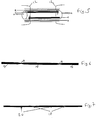
- the resistive strip can be designed to heat up the thermochromic material at spaced intervals as shown in Figure 6.
- Figure 6 This is a view of the thick-film resistive element viewed from above. It comprises repeated wide areas 14 of resistive strip interspersed with constricted areas 16. The wide areas 14 have relatively low resistance and are not heated significantly by the current passing through them. At the constrictions, however, the resistance of the strip increases significantly and heat is generated at these points, thereby warming the thermochromic material above it and changing its colour. Since the majority of the resistive strip has a relatively low resistance, the voltage required to change the colour of the thermochromic ink above the constrictions along the length of the cable is low.
- thermochromic and resistive strips may be applied to the cable in a spiral pattern in order to increase the visibility of the cable in the energized state.
- An alternative implementation uses an electrochromic or electroluminescent strip in place of the resistive element and thermochromic strip arrangement. Again, to reduce the voltage that must be applied between pins B and C of the connector, it is possible to arrange the cable construction such that only segments of the cable length change colour or emit light. Such an arrangement is shown in Figure 7. In this, segments of electrochromic or electroluminescent material 18 are connected together by longer low-resistance strips 20 of thick-film polymer. When energized, on the segments 18 of the cable will change colour or emit light as current is passed through.
- thermochromic, electrochromic or electroluminescent strip acts as a cheap flexible display element. It is suitable for use in many applications where a detailed display with many individual picture elements is not required.
- An example might be a system which guides a user through a building using floor tiles which incorporate a display strip around their edge. Location information from a fine-grain 3D tracker tells the building systems where the user is, and those systems selectively energize the display strips around the floor tiles in the direction in which the user should be progressing. After the user has passed, the building systems cease to energize those tiles, and the user is presented with a graphical display of the directions they should take.
Landscapes
- Physics & Mathematics (AREA)
- General Physics & Mathematics (AREA)
- Optics & Photonics (AREA)
- Engineering & Computer Science (AREA)
- Manufacturing & Machinery (AREA)
- Details Of Connecting Devices For Male And Female Coupling (AREA)
- Illuminated Signs And Luminous Advertising (AREA)
- Devices For Indicating Variable Information By Combining Individual Elements (AREA)
- Insulated Conductors (AREA)
Applications Claiming Priority (2)
| Application Number | Priority Date | Filing Date | Title |
|---|---|---|---|
| GB9808326 | 1998-04-20 | ||
| GB9808326A GB2336711B (en) | 1998-04-20 | 1998-04-20 | Cables |
Publications (3)
| Publication Number | Publication Date |
|---|---|
| EP0952589A2 true EP0952589A2 (de) | 1999-10-27 |
| EP0952589A3 EP0952589A3 (de) | 2000-11-29 |
| EP0952589B1 EP0952589B1 (de) | 2006-06-14 |
Family
ID=10830607
Family Applications (1)
| Application Number | Title | Priority Date | Filing Date |
|---|---|---|---|
| EP99303039A Expired - Lifetime EP0952589B1 (de) | 1998-04-20 | 1999-04-20 | Kabel |
Country Status (4)
| Country | Link |
|---|---|
| US (1) | US6596943B1 (de) |
| EP (1) | EP0952589B1 (de) |
| DE (1) | DE69931840T2 (de) |
| GB (1) | GB2336711B (de) |
Cited By (18)
| Publication number | Priority date | Publication date | Assignee | Title |
|---|---|---|---|---|
| US6954745B2 (en) | 2000-06-02 | 2005-10-11 | Canon Kabushiki Kaisha | Signal processing system |
| US7010483B2 (en) | 2000-06-02 | 2006-03-07 | Canon Kabushiki Kaisha | Speech processing system |
| US7035790B2 (en) | 2000-06-02 | 2006-04-25 | Canon Kabushiki Kaisha | Speech processing system |
| US7072833B2 (en) | 2000-06-02 | 2006-07-04 | Canon Kabushiki Kaisha | Speech processing system |
| WO2015023458A1 (en) * | 2013-08-13 | 2015-02-19 | Corning Optical Communications LLC | Optical fiber cable with cable heating element |
| US9304278B1 (en) | 2015-03-31 | 2016-04-05 | Corning Optical Communications LLC | Traceable cable with side-emitting optical fiber and method of forming the same |
| US9429731B2 (en) | 2013-08-12 | 2016-08-30 | Corning Optical Communications LLC | Optical fiber cable assembly comprising optical tracer fiber |
| US9671551B2 (en) | 2012-02-13 | 2017-06-06 | Corning Optical Communications LLC | Visual tracer system for fiber optic cable |
| US10101545B2 (en) | 2015-10-30 | 2018-10-16 | Corning Optical Communications LLC | Traceable cable assembly and connector |
| US10101553B2 (en) | 2015-05-20 | 2018-10-16 | Corning Optical Communications LLC | Traceable cable with side-emitting optical fiber and method of forming the same |
| US10107983B2 (en) | 2016-04-29 | 2018-10-23 | Corning Optical Communications LLC | Preferential mode coupling for enhanced traceable patch cord performance |
| US10185111B2 (en) | 2016-04-08 | 2019-01-22 | Corning Optical Communications LLC | Traceable end point cable assembly |
| US10222561B2 (en) | 2016-12-21 | 2019-03-05 | Corning Research & Development Corporation | Light launch device for transmitting light into a traceable fiber optic cable assembly with tracing optical fibers |
| US10228526B2 (en) | 2015-03-31 | 2019-03-12 | Corning Optical Communications LLC | Traceable cable with side-emitting optical fiber and method of forming the same |
| US10234614B2 (en) | 2017-01-20 | 2019-03-19 | Corning Research & Development Corporation | Light source assemblies and systems and methods with mode homogenization |
| US10338317B2 (en) | 2015-07-17 | 2019-07-02 | Corning Optical Communications LLC | Systems and methods for traceable cables |
| US10379309B2 (en) | 2014-11-18 | 2019-08-13 | Corning Optical Communications LLC | Traceable optical fiber cable and filtered viewing device for enhanced traceability |
| US10534135B2 (en) | 2015-07-17 | 2020-01-14 | Corning Optical Communications LLC | Systems and methods for tracing cables and cables for such systems and methods |
Families Citing this family (24)
| Publication number | Priority date | Publication date | Assignee | Title |
|---|---|---|---|---|
| US7203412B2 (en) * | 2003-09-22 | 2007-04-10 | Haskell Moore | Illuminated anti-trip cable duct |
| US20050089284A1 (en) * | 2003-10-24 | 2005-04-28 | Ming-Chuan Ma | Light emitting cable wire |
| WO2006044177A2 (en) * | 2004-10-13 | 2006-04-27 | Nortel Networks Limited | Fiber tracer patch cord |
| KR100721637B1 (ko) * | 2005-04-12 | 2007-05-23 | 엘에스전선 주식회사 | 감온변색성 전선 케이블 피복용 조성물 및 이를 이용한감온변색성 전선 케이블 |
| US7406231B1 (en) * | 2005-06-21 | 2008-07-29 | Avaya Technology Corp. | Electroluminescent patch cable |
| US7565751B2 (en) * | 2006-10-16 | 2009-07-28 | The Stanley Works | Measuring device with fluorescent translucent material |
| US20080117061A1 (en) * | 2006-11-16 | 2008-05-22 | Gaymar Industries, Inc. | Electroluminescent lighting for a managed-care setting |
| US20080121171A1 (en) * | 2006-11-28 | 2008-05-29 | Hulsey James | Temperature sensitive color changing cable apparatus |
| US8102169B2 (en) * | 2008-07-25 | 2012-01-24 | International Business Machines Corporation | Cable tracing system and method for cable management |
| US8896286B2 (en) | 2011-11-30 | 2014-11-25 | International Business Machines Corporation | Cable identification using a unique signal carried on an unused conductor |
| US20130135616A1 (en) | 2011-11-30 | 2013-05-30 | International Business Machines Corporation | Cable identification using a unique cable sleeve |
| US8606972B2 (en) | 2011-11-30 | 2013-12-10 | International Business Machines Corporation | Cable identification using data traffic activity information |
| US8896287B2 (en) | 2011-11-30 | 2014-11-25 | International Business Machines Corporation | Cable identification using a unique signal carried on an external conductor |
| US9244046B2 (en) * | 2012-12-03 | 2016-01-26 | International Business Machines Corporation | System for preventing undue bending of cables |
| CA2925465C (en) * | 2013-10-29 | 2019-01-15 | Halliburton Energy Services, Inc. | Safety cable for downhole communications |
| CN203573712U (zh) * | 2013-11-18 | 2014-04-30 | 上海广为电器工具有限公司 | 新型汽车快速启动夹线 |
| CA2935074C (en) | 2013-12-23 | 2020-08-25 | General Cable Technologies Corporation | High visibility cable |
| US9645183B2 (en) | 2014-08-20 | 2017-05-09 | At&T Intellectual Property I, L.P. | Methods, systems, and products for power management in cable assemblies |
| CN105632633B (zh) * | 2016-03-15 | 2017-07-18 | 富通集团有限公司 | 一种预警电缆及其制备方法 |
| EP3565867B1 (de) | 2017-01-04 | 2022-12-14 | ABB Schweiz AG | Thermochrome polymerzusammensetzung, elektrische vorrichtung sowie entsprechende verwendung |
| EP3566237B1 (de) * | 2017-01-04 | 2022-08-17 | ABB Schweiz AG | Temperaturempfindliche farbwechselnde elektrische vorrichtung |
| US10539747B2 (en) | 2017-12-05 | 2020-01-21 | Corning Research & Development Corporation | Bend induced light scattering fiber and cable assemblies and method of making |
| US10539758B2 (en) | 2017-12-05 | 2020-01-21 | Corning Research & Development Corporation | Traceable fiber optic cable assembly with indication of polarity |
| US11328146B2 (en) | 2020-07-28 | 2022-05-10 | Commscope Technologies Llc | Systems and methods for physical cable route tracing |
Family Cites Families (11)
| Publication number | Priority date | Publication date | Assignee | Title |
|---|---|---|---|---|
| US3069579A (en) * | 1960-03-18 | 1962-12-18 | Westinghouse Electric Corp | Electroluminescent device |
| US3442749A (en) * | 1965-08-06 | 1969-05-06 | Boeing Co | Thermal color change marking of elastomers |
| FI60463C (fi) * | 1979-12-03 | 1982-11-08 | Nokia Oy Ab | Plast- eller gummiisolerad elektrisk kabel |
| US4661305A (en) * | 1980-07-23 | 1987-04-28 | Raychem Corporation | Method of marking a substrate using a markable thermochromic article |
| DE3742412A1 (de) * | 1987-12-15 | 1989-06-29 | Hannelore Weinem | Leuchtkabel, elektrisch erregt |
| US5350885A (en) * | 1992-04-08 | 1994-09-27 | Monogram Industries, Inc. | Armored cable |
| US5900275A (en) * | 1992-07-15 | 1999-05-04 | Donnelly Corporation | Method for reducing haze in tin oxide transparent conductive coatings |
| JP3141312B2 (ja) * | 1992-12-21 | 2001-03-05 | キヤノン株式会社 | 表示素子 |
| US5416622A (en) * | 1993-02-01 | 1995-05-16 | Minnesota Mining And Manufacturing Company | Electrical connector |
| US5922996A (en) * | 1994-09-27 | 1999-07-13 | Rizzo Development Corp. | Electrical insulated cable having means for indicating malfunctions |
| US5869930A (en) * | 1996-10-22 | 1999-02-09 | Elam-Electroluminescent Industries Ltd. | Electroluminescent light source with a mixture layer filled with a transparent filler substance |
-
1998
- 1998-04-20 GB GB9808326A patent/GB2336711B/en not_active Expired - Fee Related
-
1999
- 1999-04-20 DE DE69931840T patent/DE69931840T2/de not_active Expired - Lifetime
- 1999-04-20 US US09/294,557 patent/US6596943B1/en not_active Expired - Fee Related
- 1999-04-20 EP EP99303039A patent/EP0952589B1/de not_active Expired - Lifetime
Cited By (21)
| Publication number | Priority date | Publication date | Assignee | Title |
|---|---|---|---|---|
| US6954745B2 (en) | 2000-06-02 | 2005-10-11 | Canon Kabushiki Kaisha | Signal processing system |
| US7010483B2 (en) | 2000-06-02 | 2006-03-07 | Canon Kabushiki Kaisha | Speech processing system |
| US7035790B2 (en) | 2000-06-02 | 2006-04-25 | Canon Kabushiki Kaisha | Speech processing system |
| US7072833B2 (en) | 2000-06-02 | 2006-07-04 | Canon Kabushiki Kaisha | Speech processing system |
| US9671551B2 (en) | 2012-02-13 | 2017-06-06 | Corning Optical Communications LLC | Visual tracer system for fiber optic cable |
| US9429731B2 (en) | 2013-08-12 | 2016-08-30 | Corning Optical Communications LLC | Optical fiber cable assembly comprising optical tracer fiber |
| WO2015023458A1 (en) * | 2013-08-13 | 2015-02-19 | Corning Optical Communications LLC | Optical fiber cable with cable heating element |
| US9182561B2 (en) | 2013-08-13 | 2015-11-10 | Corning Cable Systems Llc | Optical fiber cable with cable heating element |
| US10379309B2 (en) | 2014-11-18 | 2019-08-13 | Corning Optical Communications LLC | Traceable optical fiber cable and filtered viewing device for enhanced traceability |
| US10228526B2 (en) | 2015-03-31 | 2019-03-12 | Corning Optical Communications LLC | Traceable cable with side-emitting optical fiber and method of forming the same |
| US9304278B1 (en) | 2015-03-31 | 2016-04-05 | Corning Optical Communications LLC | Traceable cable with side-emitting optical fiber and method of forming the same |
| US10101553B2 (en) | 2015-05-20 | 2018-10-16 | Corning Optical Communications LLC | Traceable cable with side-emitting optical fiber and method of forming the same |
| US10338317B2 (en) | 2015-07-17 | 2019-07-02 | Corning Optical Communications LLC | Systems and methods for traceable cables |
| US10534135B2 (en) | 2015-07-17 | 2020-01-14 | Corning Optical Communications LLC | Systems and methods for tracing cables and cables for such systems and methods |
| US10101545B2 (en) | 2015-10-30 | 2018-10-16 | Corning Optical Communications LLC | Traceable cable assembly and connector |
| US10185111B2 (en) | 2016-04-08 | 2019-01-22 | Corning Optical Communications LLC | Traceable end point cable assembly |
| US10107983B2 (en) | 2016-04-29 | 2018-10-23 | Corning Optical Communications LLC | Preferential mode coupling for enhanced traceable patch cord performance |
| US10222561B2 (en) | 2016-12-21 | 2019-03-05 | Corning Research & Development Corporation | Light launch device for transmitting light into a traceable fiber optic cable assembly with tracing optical fibers |
| US10222560B2 (en) | 2016-12-21 | 2019-03-05 | Corning Research & Development Corporation | Traceable fiber optic cable assembly with fiber guide and tracing optical fibers for carrying light received from a light launch device |
| US10545298B2 (en) | 2016-12-21 | 2020-01-28 | Corning Research & Development Corporation | Traceable fiber optic cable assembly with illumination structure and tracing optical fibers for carrying light received from a light launch device |
| US10234614B2 (en) | 2017-01-20 | 2019-03-19 | Corning Research & Development Corporation | Light source assemblies and systems and methods with mode homogenization |
Also Published As
| Publication number | Publication date |
|---|---|
| GB2336711B (en) | 2002-01-09 |
| DE69931840T2 (de) | 2007-06-06 |
| GB9808326D0 (en) | 1998-06-17 |
| US6596943B1 (en) | 2003-07-22 |
| DE69931840D1 (de) | 2006-07-27 |
| GB2336711A (en) | 1999-10-27 |
| EP0952589A3 (de) | 2000-11-29 |
| EP0952589B1 (de) | 2006-06-14 |
Similar Documents
| Publication | Publication Date | Title |
|---|---|---|
| EP0952589B1 (de) | Kabel | |
| US9182561B2 (en) | Optical fiber cable with cable heating element | |
| US6717058B2 (en) | Multi-conductor cable with transparent jacket | |
| US7748860B2 (en) | Identification device for visually identifying cables or ducts over their entire length | |
| US7406231B1 (en) | Electroluminescent patch cable | |
| US7029137B2 (en) | Cable having an illuminating tracer element mounted thereon | |
| CN103069506B (zh) | 缆线护套和隔离物中的导电元件 | |
| WO2008067238A2 (en) | Temperature sensitive color changing cable apparatus | |
| KR20020011413A (ko) | 전기 가열장치 및 리셋가능 퓨즈 | |
| US10976191B2 (en) | Device comprising a flat element for laying onto a shelf element of a goods rack and system and goods presentation system having such a device | |
| NO986097D0 (no) | Varmekabel | |
| EP1022596B1 (de) | Wärmeschrumpfbarer Schlauch zum Schutz von optischen Faserspleissen | |
| AU579881B2 (en) | Electric blankets | |
| CA1297140C (en) | Tape element and methods, for heating, pressure measurement and circuit fabrication | |
| CA2313997C (en) | Reticulate heater | |
| CA2081029A1 (en) | Elongated electrical resistance heater | |
| SE9902390L (sv) | Anordning för uppvärmning av krymphylsor | |
| JPH02236914A (ja) | リボン同軸ケーブル | |
| GB2168580A (en) | Electric blanket or pad | |
| FR2753562A1 (fr) | Cable de telecommunication pour signaux a haut debit | |
| US20220051832A1 (en) | Wiring member | |
| JP6639097B2 (ja) | 温度検出体及び温度検出装置 | |
| CN213071651U (zh) | 一种感温电子线束 | |
| NL1005647C2 (nl) | Elektrische kabel, en gebruik van een dergelijke kabel. | |
| US6973721B2 (en) | Tension-resistant connection between a shielded heating cable and a power supply cable |
Legal Events
| Date | Code | Title | Description |
|---|---|---|---|
| PUAI | Public reference made under article 153(3) epc to a published international application that has entered the european phase |
Free format text: ORIGINAL CODE: 0009012 |
|
| AK | Designated contracting states |
Kind code of ref document: A2 Designated state(s): DE FR |
|
| AX | Request for extension of the european patent |
Free format text: AL;LT;LV;MK;RO;SI |
|
| PUAL | Search report despatched |
Free format text: ORIGINAL CODE: 0009013 |
|
| AK | Designated contracting states |
Kind code of ref document: A3 Designated state(s): AT BE CH CY DE DK ES FI FR GB GR IE IT LI LU MC NL PT SE |
|
| AX | Request for extension of the european patent |
Free format text: AL;LT;LV;MK;RO;SI |
|
| 17P | Request for examination filed |
Effective date: 20010227 |
|
| AKX | Designation fees paid |
Free format text: DE FR |
|
| 17Q | First examination report despatched |
Effective date: 20040310 |
|
| GRAP | Despatch of communication of intention to grant a patent |
Free format text: ORIGINAL CODE: EPIDOSNIGR1 |
|
| GRAS | Grant fee paid |
Free format text: ORIGINAL CODE: EPIDOSNIGR3 |
|
| GRAA | (expected) grant |
Free format text: ORIGINAL CODE: 0009210 |
|
| AK | Designated contracting states |
Kind code of ref document: B1 Designated state(s): DE FR |
|
| REF | Corresponds to: |
Ref document number: 69931840 Country of ref document: DE Date of ref document: 20060727 Kind code of ref document: P |
|
| ET | Fr: translation filed | ||
| PLBE | No opposition filed within time limit |
Free format text: ORIGINAL CODE: 0009261 |
|
| STAA | Information on the status of an ep patent application or granted ep patent |
Free format text: STATUS: NO OPPOSITION FILED WITHIN TIME LIMIT |
|
| 26N | No opposition filed |
Effective date: 20070315 |
|
| PGFP | Annual fee paid to national office [announced via postgrant information from national office to epo] |
Ref country code: DE Payment date: 20120430 Year of fee payment: 14 |
|
| PGFP | Annual fee paid to national office [announced via postgrant information from national office to epo] |
Ref country code: FR Payment date: 20120503 Year of fee payment: 14 |
|
| PG25 | Lapsed in a contracting state [announced via postgrant information from national office to epo] |
Ref country code: DE Free format text: LAPSE BECAUSE OF NON-PAYMENT OF DUE FEES Effective date: 20131101 |
|
| REG | Reference to a national code |
Ref country code: FR Ref legal event code: ST Effective date: 20131231 |
|
| REG | Reference to a national code |
Ref country code: DE Ref legal event code: R119 Ref document number: 69931840 Country of ref document: DE Effective date: 20131101 |
|
| PG25 | Lapsed in a contracting state [announced via postgrant information from national office to epo] |
Ref country code: FR Free format text: LAPSE BECAUSE OF NON-PAYMENT OF DUE FEES Effective date: 20130430 |