EP0952596A2 - Disjoncteur basse tension avec rail de contact enfichable - Google Patents
Disjoncteur basse tension avec rail de contact enfichable Download PDFInfo
- Publication number
- EP0952596A2 EP0952596A2 EP99250134A EP99250134A EP0952596A2 EP 0952596 A2 EP0952596 A2 EP 0952596A2 EP 99250134 A EP99250134 A EP 99250134A EP 99250134 A EP99250134 A EP 99250134A EP 0952596 A2 EP0952596 A2 EP 0952596A2
- Authority
- EP
- European Patent Office
- Prior art keywords
- circuit breaker
- voltage circuit
- low
- horn
- breaker according
- Prior art date
- Legal status (The legal status is an assumption and is not a legal conclusion. Google has not performed a legal analysis and makes no representation as to the accuracy of the status listed.)
- Withdrawn
Links
- 238000010791 quenching Methods 0.000 claims description 5
- 230000000171 quenching effect Effects 0.000 claims description 5
- 239000002184 metal Substances 0.000 claims description 4
- 239000004020 conductor Substances 0.000 claims description 2
- 238000003780 insertion Methods 0.000 abstract description 4
- 230000037431 insertion Effects 0.000 abstract description 4
- 238000004519 manufacturing process Methods 0.000 description 5
- 239000000463 material Substances 0.000 description 4
- 230000006835 compression Effects 0.000 description 1
- 238000007906 compression Methods 0.000 description 1
- 238000009434 installation Methods 0.000 description 1
- 239000011810 insulating material Substances 0.000 description 1
- 238000012423 maintenance Methods 0.000 description 1
- 238000000034 method Methods 0.000 description 1
- 239000007787 solid Substances 0.000 description 1
Images
Classifications
-
- H—ELECTRICITY
- H01—ELECTRIC ELEMENTS
- H01H—ELECTRIC SWITCHES; RELAYS; SELECTORS; EMERGENCY PROTECTIVE DEVICES
- H01H1/00—Contacts
- H01H1/58—Electric connections to or between contacts; Terminals
-
- H—ELECTRICITY
- H01—ELECTRIC ELEMENTS
- H01H—ELECTRIC SWITCHES; RELAYS; SELECTORS; EMERGENCY PROTECTIVE DEVICES
- H01H11/00—Apparatus or processes specially adapted for the manufacture of electric switches
- H01H11/04—Apparatus or processes specially adapted for the manufacture of electric switches of switch contacts
- H01H11/06—Fixing of contacts to carrier ; Fixing of contacts to insulating carrier
-
- H—ELECTRICITY
- H01—ELECTRIC ELEMENTS
- H01H—ELECTRIC SWITCHES; RELAYS; SELECTORS; EMERGENCY PROTECTIVE DEVICES
- H01H9/00—Details of switching devices, not covered by groups H01H1/00 - H01H7/00
- H01H9/30—Means for extinguishing or preventing arc between current-carrying parts
- H01H9/46—Means for extinguishing or preventing arc between current-carrying parts using arcing horns
Definitions
- the invention relates to a low-voltage circuit breaker with a housing and a contact system located in this housing, which has at least one insertable busbar fixed by fastening means for connecting the contact system to an external circuit, in particular the area of the upper fixed switching contact, which has an arcing horn is provided.
- This fixed contact is located on a solid rail that is passed through an insulating wall part of the housing. The contact is on the inside and an additional rail can be screwed onto the part that is pushed outwards, or a disconnect contact can be attached to slide-in switches.
- This upper rail with the fixed switching contact must be fixed in the insulating wall body, since during the switching process the movable contacts hit the fixed contact with full force. So it is a strong and dynamic place.
- screws serve as fastening means for the busbar, which extend through openings arranged transversely to the longitudinal axis of the connecting rails and for which a corresponding nut thread is provided in the rear wall of the housing.
- metallic insert nuts or press-in nuts are used here.
- busbars In the case of the circuit breakers mentioned with high rated currents of, for example, 1000 to 6000 A, the busbars have a considerable cross section. That's why they're with several cross holes and a corresponding number of fasteners is required. The manufacture and installation of such busbars is therefore associated with a high cost of materials and manufacturing.
- the object of the present invention is to provide an arrangement which, even in the assembled state of the switch, ensures good accessibility to the fastening of the busbar, for example for control and maintenance purposes, and the material expenditure for the production and the expenditure for the assembly keeps the track in the housing low.
- a low-voltage circuit breaker with a housing and a contact system located in this housing, which has two busbars fixed by fastening means for connecting the contact system to an external circuit
- the upper fixed switching contact is provided with an arcing horn
- the busbar of this contact has at least one integrally formed web extending transversely to its longitudinal direction, which comes into contact with an abutment surface of the rear wall of the housing after insertion of the busbar into the through opening of the rear wall of the housing, as a fastening means the arcing horn is used to fix the busbar in the opening in the rear wall of the housing.
- the arc horn designed as a stamped and bent part made of sheet metal is provided at the end opposite the horn area, which leads the arc in the direction of the quenching chamber, with a pressed-out stop bar for abutment against a wall shoulder provided for this purpose in the through opening of the rear wall of the housing.
- a stop bar one or more stops pushed out can also be expediently provided.
- the arcing horn has two or more holes for fastening screws between the pressed-out stops and the horn region, which leads the arc in the direction of the arcing chamber. To overcome tolerance problems, these holes can be designed as elongated holes.
- the diameter of round holes for the fastening screws can be larger than the diameter of the fastening screws passed therethrough. Then the arrangement can be adjusted accordingly after insertion by pulling the arcing horn forward after insertion and compression, in such a way that it lies firmly against the wall shoulder at the back and then the fastening screws are tightened and produce a frictional engagement due to their pressure, which is a Moving the busbar against the arcing horn prevented. That should be enough for normal switches; with high switching and contact forces, an additional fuse may be required.
- both the round holes for the fastening screws and the eccentric discs have a toothed edge on their outer diameter.
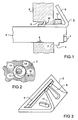
- FIG. 1 schematically shows a possible arrangement of the busbar and the arcing horn in the rear wall of the low-voltage circuit breaker.
- FIG. 2 shows a perspective view of an example embodiment of the arcing horn.
- FIG. 3 shows a schematic, partial sectional illustration of the use of an eccentric disk for absorbing very high switching and contact forces.
- the upper fixed switch contact 1 is shown, which is provided with an arcing horn 2.
- the busbar 3 of this switching contact 1 has an integrally formed web 4 which extends transversely to its longitudinal direction and comes into contact with a stop face 7 of the back wall 6 after the introduction of the busbar 3 into the lead-through opening 5 of the back wall 6.
- the busbar 3 is supported in the direction of the forces occurring. Due to the one-sided arrangement of the web 4, however, a torque or tilting moment arises from the switching and contact forces. Therefore, the final fastening of the busbar 3 in the through opening 5 of the rear wall 6 is to be effected by the arcing horn 2.
- the arc horn 2 which is designed as a stamped and bent part made of sheet metal, is provided at the end opposite the horn region 8, which leads the arc in the direction of the quenching chamber, with a pressed-out stop bar 9 for abutment against a wall shoulder 10 provided for this purpose in the through opening 5 of the rear wall 6 of the housing .
- the arc horn 2 is shown in perspective in FIG. It has two or more holes for fastening screws 12 between the pressed-out stop bar 9 and the horn region 8, which leads the arc in the direction of the quenching chamber, for fastening to and fixing the busbar 3.
- the holes are designed as elongated holes 11. It is assumed that the frictional connection of the connection between the busbar 3 and the arcing horn 2 caused by the contact pressure of the fastening screws 12 is sufficient to prevent the busbar 3 from shifting relative to the arcing horn 2.
- FIG. 3 shows a further possibility for overcoming the tolerance problems, which is particularly suitable for high stresses caused by the switching and contact forces.
- the diameter of the round holes 13 is larger than the diameter of the fastening screws 12 passed through.
- eccentric discs 14 inserted, the form-fitting support of the arcing horn 2 on the in the busbar 3rd form screwed fastening screw 12 against the forces acting in the direction of arrow 15.
- the arcing horn 2 is first arranged in the through opening 5 such that it abuts the wall ledge 10 in the through opening 5 with the stop bar 9. Then the busbar 3 is inserted from the inside into the through opening 5 of the insulating housing rear wall 6 until the integrally formed web 4 bears against the stop surface 7. By tightening the fastening screws 12 of the arcing horn 2, the arrangement of the busbar 3 / arcing horn 2 is finally fixed.
- the advantages of the invention are that the mounting of the busbar and the arcing horn is accessible when the switch is assembled, and the arrangement requires less material and production.
Landscapes
- Physics & Mathematics (AREA)
- Electromagnetism (AREA)
- Engineering & Computer Science (AREA)
- Manufacturing & Machinery (AREA)
- Arc-Extinguishing Devices That Are Switches (AREA)
Applications Claiming Priority (2)
| Application Number | Priority Date | Filing Date | Title |
|---|---|---|---|
| DE1998119165 DE19819165A1 (de) | 1998-04-24 | 1998-04-24 | Niederspannungs-Leistungsschalter mit einer einschiebbaren Stromschiene |
| DE19819165 | 1998-04-24 |
Publications (2)
| Publication Number | Publication Date |
|---|---|
| EP0952596A2 true EP0952596A2 (fr) | 1999-10-27 |
| EP0952596A3 EP0952596A3 (fr) | 2000-06-14 |
Family
ID=7866179
Family Applications (1)
| Application Number | Title | Priority Date | Filing Date |
|---|---|---|---|
| EP99250134A Withdrawn EP0952596A3 (fr) | 1998-04-24 | 1999-04-23 | Disjoncteur basse tension avec rail de contact enfichable |
Country Status (2)
| Country | Link |
|---|---|
| EP (1) | EP0952596A3 (fr) |
| DE (1) | DE19819165A1 (fr) |
Families Citing this family (1)
| Publication number | Priority date | Publication date | Assignee | Title |
|---|---|---|---|---|
| DE10219558B4 (de) | 2002-04-26 | 2004-08-26 | Siemens Ag | Elektrischer Leistungsschalter mit einer Anschlussschiene und einem Lichtbogenhorn |
Family Cites Families (2)
| Publication number | Priority date | Publication date | Assignee | Title |
|---|---|---|---|---|
| DE3679291D1 (de) * | 1985-10-31 | 1991-06-20 | Merlin Gerin | Kinematische uebertragungskette zwischen dem steuermechanismus und den polen eines elektrischen lastschalters mit einem gespritzten isoliergehaeuse. |
| DE19643607A1 (de) * | 1996-05-13 | 1997-11-20 | Siemens Ag | Leistungsschalter für Niederspannung mit Anschlußschienen |
-
1998
- 1998-04-24 DE DE1998119165 patent/DE19819165A1/de not_active Withdrawn
-
1999
- 1999-04-23 EP EP99250134A patent/EP0952596A3/fr not_active Withdrawn
Also Published As
| Publication number | Publication date |
|---|---|
| EP0952596A3 (fr) | 2000-06-14 |
| DE19819165A1 (de) | 1999-10-28 |
Similar Documents
| Publication | Publication Date | Title |
|---|---|---|
| EP1277258B1 (fr) | Connecteur pour barres omnibus | |
| EP0898779B1 (fr) | Disjoncteur pour basse tension avec rails de raccordement | |
| DE102007041650A1 (de) | Installationsschaltgerät und Anschlussklemme für ein Installationsschaltgerät | |
| EP0168596B1 (fr) | Borne de connexion et procédé pour sa fabrication | |
| DE3621071A1 (de) | Klemmelement | |
| EP0223732B1 (fr) | Disjoncteur multipolaire de puissance basse tension avec barres de courant | |
| EP1065683B1 (fr) | Disjoncteur aves des bornes pour plusieurs intensités nominales | |
| DE9417134U1 (de) | Datenübertragungsssystem | |
| WO2006069634A1 (fr) | Dispositif de fixation rapide sur un appareil d'installation electrique | |
| EP1297547B1 (fr) | Barrette a connexions pour dispositifs et appareils electriques utilisables pour differents courants nominaux et comportant une cavite | |
| WO2001013391A1 (fr) | Profiles de raccordement d'appareils et de dispositifs electriques destines a differents courants nominaux | |
| DE19819165A1 (de) | Niederspannungs-Leistungsschalter mit einer einschiebbaren Stromschiene | |
| DE2543959A1 (de) | Adapter fuer sicherungslastschalter zur befestigung auf stromsammelschienen | |
| DE10260371A1 (de) | Niederspannungs-Leistungsschalter | |
| EP1454396A2 (fr) | Traversee | |
| EP0654877A2 (fr) | Armoire de commutation avec ouvertures de ventilation | |
| EP1026801B1 (fr) | Bloc de contacts mobile pour interrupteur de puissance extractible | |
| DE3007970A1 (de) | Elektrische schaltanlage | |
| EP1344234B1 (fr) | Rail de raccordement en demi-produits profiles pour appareils electriques et courant nominaux differents | |
| EP0910858B1 (fr) | Dispositif de contact de commutation pourvu d'une articulation destinee a un levier de contact | |
| EP1028488B1 (fr) | Borne de connexion pour un appareillage d'installation électrique | |
| EP0639846B1 (fr) | Arbre de commande pour un interrupteur d'installation | |
| DE202005014853U1 (de) | Anschlussbaugruppe für einen Leistungsschalter sowie Leistungsschalter | |
| WO2001039225A1 (fr) | Configuration de contact de commutation de commande comprenant un module fixe constitue d'un contact d'arc et d'une corne d'arc | |
| DE10119611A1 (de) | Sicherungslasttrennschalter in Leistenbauform |
Legal Events
| Date | Code | Title | Description |
|---|---|---|---|
| PUAI | Public reference made under article 153(3) epc to a published international application that has entered the european phase |
Free format text: ORIGINAL CODE: 0009012 |
|
| AK | Designated contracting states |
Kind code of ref document: A2 Designated state(s): DE FR GB IT |
|
| AX | Request for extension of the european patent |
Free format text: AL;LT;LV;MK;RO;SI |
|
| PUAL | Search report despatched |
Free format text: ORIGINAL CODE: 0009013 |
|
| AK | Designated contracting states |
Kind code of ref document: A3 Designated state(s): AT BE CH CY DE DK ES FI FR GB GR IE IT LI LU MC NL PT SE |
|
| AX | Request for extension of the european patent |
Free format text: AL;LT;LV;MK;RO;SI |
|
| 17P | Request for examination filed |
Effective date: 20000801 |
|
| AKX | Designation fees paid |
Free format text: DE FR GB IT |
|
| GRAP | Despatch of communication of intention to grant a patent |
Free format text: ORIGINAL CODE: EPIDOSNIGR1 |
|
| STAA | Information on the status of an ep patent application or granted ep patent |
Free format text: STATUS: THE APPLICATION IS DEEMED TO BE WITHDRAWN |
|
| 18D | Application deemed to be withdrawn |
Effective date: 20070105 |