EP0952597A1 - Clavier pour l'entrée d'instructions de commande - Google Patents
Clavier pour l'entrée d'instructions de commande Download PDFInfo
- Publication number
- EP0952597A1 EP0952597A1 EP99107090A EP99107090A EP0952597A1 EP 0952597 A1 EP0952597 A1 EP 0952597A1 EP 99107090 A EP99107090 A EP 99107090A EP 99107090 A EP99107090 A EP 99107090A EP 0952597 A1 EP0952597 A1 EP 0952597A1
- Authority
- EP
- European Patent Office
- Prior art keywords
- keyboard
- bearing plate
- keys
- mat
- switching
- Prior art date
- Legal status (The legal status is an assumption and is not a legal conclusion. Google has not performed a legal analysis and makes no representation as to the accuracy of the status listed.)
- Granted
Links
- 239000012528 membrane Substances 0.000 claims description 27
- 238000003825 pressing Methods 0.000 claims description 3
- 230000000694 effects Effects 0.000 claims description 2
- 239000002184 metal Substances 0.000 claims description 2
- 229910052751 metal Inorganic materials 0.000 claims description 2
- 229920002379 silicone rubber Polymers 0.000 claims description 2
- 239000004945 silicone rubber Substances 0.000 claims description 2
- 239000011888 foil Substances 0.000 abstract 1
- 230000001960 triggered effect Effects 0.000 description 7
- 239000004020 conductor Substances 0.000 description 4
- 238000003860 storage Methods 0.000 description 4
- 238000010276 construction Methods 0.000 description 3
- 238000005260 corrosion Methods 0.000 description 2
- 230000007797 corrosion Effects 0.000 description 2
- 238000004519 manufacturing process Methods 0.000 description 2
- 238000000034 method Methods 0.000 description 2
- 230000003647 oxidation Effects 0.000 description 2
- 238000007254 oxidation reaction Methods 0.000 description 2
- 229910001229 Pot metal Inorganic materials 0.000 description 1
- 238000011109 contamination Methods 0.000 description 1
- 238000001514 detection method Methods 0.000 description 1
- 238000011161 development Methods 0.000 description 1
- 230000018109 developmental process Effects 0.000 description 1
- 238000001746 injection moulding Methods 0.000 description 1
- 238000009434 installation Methods 0.000 description 1
- 238000012423 maintenance Methods 0.000 description 1
- 239000000463 material Substances 0.000 description 1
- 239000006187 pill Substances 0.000 description 1
Images




Classifications
-
- H—ELECTRICITY
- H01—ELECTRIC ELEMENTS
- H01H—ELECTRIC SWITCHES; RELAYS; SELECTORS; EMERGENCY PROTECTIVE DEVICES
- H01H13/00—Switches having rectilinearly-movable operating part or parts adapted for pushing or pulling in one direction only, e.g. push-button switch
- H01H13/70—Switches having rectilinearly-movable operating part or parts adapted for pushing or pulling in one direction only, e.g. push-button switch having a plurality of operating members associated with different sets of contacts, e.g. keyboard
- H01H13/702—Switches having rectilinearly-movable operating part or parts adapted for pushing or pulling in one direction only, e.g. push-button switch having a plurality of operating members associated with different sets of contacts, e.g. keyboard with contacts carried by or formed from layers in a multilayer structure, e.g. membrane switches
-
- H—ELECTRICITY
- H01—ELECTRIC ELEMENTS
- H01H—ELECTRIC SWITCHES; RELAYS; SELECTORS; EMERGENCY PROTECTIVE DEVICES
- H01H2215/00—Tactile feedback
- H01H2215/004—Collapsible dome or bubble
- H01H2215/006—Only mechanical function
-
- H—ELECTRICITY
- H01—ELECTRIC ELEMENTS
- H01H—ELECTRIC SWITCHES; RELAYS; SELECTORS; EMERGENCY PROTECTIVE DEVICES
- H01H2215/00—Tactile feedback
- H01H2215/004—Collapsible dome or bubble
- H01H2215/008—Part of substrate or membrane
-
- H—ELECTRICITY
- H01—ELECTRIC ELEMENTS
- H01H—ELECTRIC SWITCHES; RELAYS; SELECTORS; EMERGENCY PROTECTIVE DEVICES
- H01H2221/00—Actuators
- H01H2221/008—Actuators other then push button
- H01H2221/016—Lever; Rocker
-
- H—ELECTRICITY
- H01—ELECTRIC ELEMENTS
- H01H—ELECTRIC SWITCHES; RELAYS; SELECTORS; EMERGENCY PROTECTIVE DEVICES
- H01H2221/00—Actuators
- H01H2221/036—Return force
- H01H2221/044—Elastic part on actuator or casing
-
- H—ELECTRICITY
- H01—ELECTRIC ELEMENTS
- H01H—ELECTRIC SWITCHES; RELAYS; SELECTORS; EMERGENCY PROTECTIVE DEVICES
- H01H2221/00—Actuators
- H01H2221/05—Force concentrator; Actuating dimple
-
- H—ELECTRICITY
- H01—ELECTRIC ELEMENTS
- H01H—ELECTRIC SWITCHES; RELAYS; SELECTORS; EMERGENCY PROTECTIVE DEVICES
- H01H2221/00—Actuators
- H01H2221/064—Limitation of actuating pressure
-
- H—ELECTRICITY
- H01—ELECTRIC ELEMENTS
- H01H—ELECTRIC SWITCHES; RELAYS; SELECTORS; EMERGENCY PROTECTIVE DEVICES
- H01H2223/00—Casings
- H01H2223/002—Casings sealed
-
- H—ELECTRICITY
- H01—ELECTRIC ELEMENTS
- H01H—ELECTRIC SWITCHES; RELAYS; SELECTORS; EMERGENCY PROTECTIVE DEVICES
- H01H2223/00—Casings
- H01H2223/042—Casings mounted in conventional keyboard
-
- H—ELECTRICITY
- H01—ELECTRIC ELEMENTS
- H01H—ELECTRIC SWITCHES; RELAYS; SELECTORS; EMERGENCY PROTECTIVE DEVICES
- H01H2229/00—Manufacturing
- H01H2229/034—Positioning of layers
-
- H—ELECTRICITY
- H01—ELECTRIC ELEMENTS
- H01H—ELECTRIC SWITCHES; RELAYS; SELECTORS; EMERGENCY PROTECTIVE DEVICES
- H01H2229/00—Manufacturing
- H01H2229/062—Maintenance or repair facilities
-
- H—ELECTRICITY
- H01—ELECTRIC ELEMENTS
- H01H—ELECTRIC SWITCHES; RELAYS; SELECTORS; EMERGENCY PROTECTIVE DEVICES
- H01H2231/00—Applications
- H01H2231/03—Elevator
-
- H—ELECTRICITY
- H01—ELECTRIC ELEMENTS
- H01H—ELECTRIC SWITCHES; RELAYS; SELECTORS; EMERGENCY PROTECTIVE DEVICES
- H01H2233/00—Key modules
- H01H2233/002—Key modules joined to form button rows
- H01H2233/004—One molded part
Definitions
- the invention relates to a keyboard for entering control commands, such as those used in particular for call entry in elevators.
- a keyboard for entering control commands has become known from US Pat. No. 5,664,667, in which a switch mat is equipped with buttons which are placed on a print provided with electrical switch contacts and circuits.
- the buttons have switching cams equipped with contacts that act directly on the corresponding contacts of the print when a button is pressed and can thus trigger a control command.
- the contact is triggered by directly touching the contacted switching cam of the button with the print or. with the contact area on the print. Due to the open construction of this keyboard, moisture can penetrate between the switch mat and the print provided with conductor tracks and switch contacts. This leads to rapid corrosion and / or oxidation of the switch contacts and conductor tracks and can consequently lead to short circuits and thus to an unsatisfactorily short lifespan of the keyboard. Furthermore, the force exerted when the keys are operated is transferred directly to the contact surface of the print and, if the force is too great, it can be intentional or unintentional to destroy the keyboard.
- the invention has for its object to provide a keyboard for entering control commands of the type mentioned, which does not have the aforementioned disadvantages.
- the advantages achieved by the invention are essentially to be seen in the fact that the switching process to be triggered by buttons takes place in a closed unit in the form of a bearing plate which comprises a keyboard mat and a membrane keyboard, the switching contacts being located in the membrane keyboard sealed against moisture.
- the call is recorded in the moisture-proof membrane keyboard and the switch cams on the keyboard mat only have a trigger function.
- the closed unit in the form of the bearing plate also makes installation considerably easier, since the keyboard mat and the membrane keyboard can be pre-assembled in the bearing plate at the factory and only a keypad has to be attached on site.
- buttons placed on the closed unit are combined into a keypad by means of film hinges and are each provided with a stop that acts on the bearing plate, so that the key stroke is limited by the stop after the contact has been triggered, even if the button is pressed too hard.
- FIG. 1 shows a view of a membrane keyboard 1.
- This membrane keyboard 1 is sealed against the effects of moisture and is provided, for example, with fifteen contacts 2.
- the number of contacts 2 can be freely selected depending on the size or the desired number of keyboard signals to be triggered.
- the contacts 2 each have two contact surfaces 3, which are separated from one another by an air or gas cushion and form a so-called contact chamber, this air or gas cushion representing the switching path. If mechanical pressure is now exerted on a contact 2, the air or gas cushion is pressed together until the two contact surfaces 3 touch and the desired signal is triggered. After the pressure on contact 2 has ended, the air or gas cushion expands back into the starting position and contact 2 is opened again.
- Contact chambers are connected to one another via connection channels (not shown in the figure) for the purpose of pressure equalization and thereby improve the switching behavior.
- This membrane keyboard 1 or the contacts 2 separated by an air or gas cushion are particularly characterized by the long service life (a few million switching operations) and the inexpensive manufacture.
- conductor tracks (not shown) are inserted in the membrane keyboard 1 in FIG. 1 and are led out of the contacts 2 via a tongue 4 in order to be able to process the signals in an electronics or control unit.
- the seal against moisture and the isolated triggering of contacts protect the contacts 2 and the electrical connections in the form of, for example, conductor tracks or circuits against contamination, corrosion or oxidation.
- Openings 6 are provided in order to position the membrane keyboard 1 precisely in a bearing plate or bearing pocket 5 shown according to FIGS. 3a and 3b. These openings 6 are arranged in such a way that they fit over pins attached to the bearing pocket 5 and the membrane keyboard 1 is thus fixed.
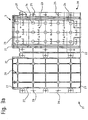
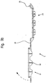
- FIG. 2a shows the view and FIG. 2b shows the side elevation of a keyboard mat 10, which is preferably made of silicone rubber or a material with similar properties.
- the keyboard mat 10 has switching cams 11, the number and positions of which correspond to the contacts 2 of the membrane keyboard 1. Openings 12 are also provided on the keyboard mat 10, so that the keyboard mat 10 is positioned over the pins of the bearing plate 5 and the switching cams 11 lie over the contacts 2 of the membrane keyboard 1.
- FIG 2c shows an enlarged section of a switching cam 11 according to Figures 2a and 2b.
- the switching cam 11 essentially consists of a switching element 13 and a dome 14.
- the domes 14 of the switching cams 11 are each constructed in such a way that a defined switching point for the switching element 13 is given. This means that the dome 14 has a precisely defined sticking point or a tipping point, which is overcome with a certain force on the switching cam 11.
- the switching element 13 is then on the underlying contact 2, respectively. pressed the contact surfaces 3 of the membrane keyboard 1 and thus triggers a signal.
- the keyboard mat 10 has cutouts 17 in the area of the switching cams 11 or the domes 14.
- the switching element 13 can be pressed onto the underlying contact 2 of the membrane keyboard 1.
- this construction differs fundamentally in that the switching element 13 is not provided with a contact surface or a contact pill, but only has the function of triggering a call.
- the actual call detection takes place in the sealed membrane keyboard 1 by pressing the two contact surfaces 3 together.
- FIG. 3a shows a view
- FIG. 3b shows a side elevation of a bearing plate or bearing pocket 5.
- This bearing plate 5 has the task of receiving and fixing the membrane keyboard 1 and the keyboard mat 10.
- the bearing plate 5 consists of an upper part 20 and a lower part 21, which are connected to one another via a film hinge 22. Upper part 20 and lower part 21 are in one piece, so that the entire storage pocket 5 can be produced in one piece in an injection molding tool.
- the lower part 21 has ribs 28 in the form of webs up to the rear wall, which serves both for stiffening the bearing plate 5 and also for dissipating force when the buttons are pressed too hard.
- the upper part 20 contains pins 23, the spacing of which corresponds to that of the openings 6 of the membrane keyboard and that of the openings 12 of the keyboard mat 10. Furthermore, openings 24 are provided on the upper part 20, the spacing of which corresponds to that of the switching cams 11 of the keyboard mat 10. This Openings 24 serve to establish the connection between the switching cams 11 and the keys of the keypad 16.
- the bearing plate 5 can be closed. As indicated in FIG. 3b with an arrow, the bearing plate 5 is closed by the lower part 21 being folded onto the upper part 20 via the film hinge 22.
- a closure is provided which allows a one-time closure or a closure can be used which can be opened again for maintenance.
- cams 25 with a conical tip can be arranged on the upper part, which fit into holes 26 on the lower part 21, the diameter of the holes 26 being slightly smaller than the largest diameter of the conical tip of the cam 25.
- the closed storage plate or storage bag 5 represents a complete, protected and functional unit and also considerably simplifies assembly, since the keyboard mat 10 and the membrane keyboard 1 can already be factory-assembled in the storage plate 5 and only one on site as in FIGS. 4a and b described keypad 16 must be placed.
- fastening holes 27 are provided on the upper part 20 and on the lower part 21, which lie one above the other in the closed state of the bearing plate 5.
- FIG. 4a shows a side view
- FIG. 4b shows a view of a keypad 16.
- This keypad 16 as it is can be used in particular in an elevator system, for example a numeric keypad with further additional functions such as a handicapped key etc., is made in one piece and consists of keys 30 and a frame element 31. Film hinges 32 firstly connect the keys 30 to the frame element 31, for others enable the switching movement of the keys 30.
- the key block 16 can consist entirely of plastic, the keys 30 being provided with plastic-injected symbols and / or numbers.
- the actual keys 30 can consist of metal, for example of die-cast zinc, with plastic-injected numbers and symbols, the remaining elements, such as the frame element 31 and the film hinge 32, being made of plastic.
- Fastening pins 33 are attached to the back of the keypad 16, by means of which the keypad 16 can be snapped onto the closed bearing plate 5 by pressing the fastening pins 33 into the associated fastening holes 27 of the bearing plate 5.
- a switching strip 34 on the back of each button 30 establishes the connection to the corresponding switching cam 11 of the keyboard mat 10 when a button is pressed, through which the call is finally triggered on the contact 2 of the membrane keyboard 1.
- a stop 35 has the task of limiting the switching distance to the switching cams 11 and in order to prevent the keyboard mat 10 or the membrane keyboard 1 from being destroyed if the force exerted on the push button 30 by the stop 35 acting on the outside of the closed bearing plate 5.
- Figure 5 shows a perspective view of the entire keyboard.
- This closed unit can be preassembled and installed in the terminal in production in a short time, and, if necessary, delivered directly to the construction site as a spare part. Time can thus be saved during assembly and, in addition, the membrane keyboard 1 and the keyboard mat 10 are protected against damage by the closed bearing plate 5.
- Another advantage is that no additional fasteners are required to assemble the keyboard.
- only the keypad 16 has to be snapped onto the bearing plate 5.
Landscapes
- Push-Button Switches (AREA)
- Input From Keyboards Or The Like (AREA)
- Input Circuits Of Receivers And Coupling Of Receivers And Audio Equipment (AREA)
- Electrophonic Musical Instruments (AREA)
- Rotary Switch, Piano Key Switch, And Lever Switch (AREA)
- Selective Calling Equipment (AREA)
Priority Applications (1)
| Application Number | Priority Date | Filing Date | Title |
|---|---|---|---|
| EP99107090A EP0952597B1 (fr) | 1998-04-23 | 1999-04-12 | Clavier pour l'entrée d'instructions de commande |
Applications Claiming Priority (3)
| Application Number | Priority Date | Filing Date | Title |
|---|---|---|---|
| EP98810360 | 1998-04-23 | ||
| EP98810360 | 1998-04-23 | ||
| EP99107090A EP0952597B1 (fr) | 1998-04-23 | 1999-04-12 | Clavier pour l'entrée d'instructions de commande |
Publications (2)
| Publication Number | Publication Date |
|---|---|
| EP0952597A1 true EP0952597A1 (fr) | 1999-10-27 |
| EP0952597B1 EP0952597B1 (fr) | 2006-02-08 |
Family
ID=8236051
Family Applications (1)
| Application Number | Title | Priority Date | Filing Date |
|---|---|---|---|
| EP99107090A Expired - Lifetime EP0952597B1 (fr) | 1998-04-23 | 1999-04-12 | Clavier pour l'entrée d'instructions de commande |
Country Status (10)
| Country | Link |
|---|---|
| US (1) | US6087600A (fr) |
| EP (1) | EP0952597B1 (fr) |
| JP (1) | JP2000112622A (fr) |
| CN (1) | CN1118076C (fr) |
| AT (1) | ATE317588T1 (fr) |
| CA (1) | CA2269391C (fr) |
| DE (1) | DE59913104D1 (fr) |
| ES (1) | ES2258303T3 (fr) |
| MY (1) | MY123279A (fr) |
| SG (1) | SG85634A1 (fr) |
Families Citing this family (7)
| Publication number | Priority date | Publication date | Assignee | Title |
|---|---|---|---|---|
| US6781071B2 (en) * | 2000-04-20 | 2004-08-24 | Delphi Technologies, Inc. | Electrical switch actuating element |
| KR100713414B1 (ko) * | 2004-11-24 | 2007-05-04 | 삼성전자주식회사 | 업/다운 키들을 구비한 휴대 통신 장치 |
| US7629547B2 (en) * | 2006-04-24 | 2009-12-08 | Nokia Corporation | Illuminating of an electrical device |
| JP4749404B2 (ja) * | 2007-10-15 | 2011-08-17 | アール・ビー・コントロールズ株式会社 | スイッチ基板の保持構造 |
| JP2011510459A (ja) * | 2008-01-24 | 2011-03-31 | パナソニック株式会社 | キースイッチ及び電子機器 |
| EP3347296B1 (fr) | 2015-09-11 | 2019-11-27 | Inventio AG | Panneau de fonctionnement pour un ascenseur avec interrupteur à clé protégé contre les projections d'eau |
| EP3817169B1 (fr) | 2019-10-28 | 2022-02-09 | KONE Corporation | Station d'inspection |
Citations (4)
| Publication number | Priority date | Publication date | Assignee | Title |
|---|---|---|---|---|
| GB2068643A (en) * | 1980-02-04 | 1981-08-12 | Rogers Corp | Electric switch assembly and keyboard device |
| US4532575A (en) * | 1981-12-29 | 1985-07-30 | Canon Kabushiki Kaisha | Electronic equipment having key input function |
| DE19627184A1 (de) * | 1995-07-07 | 1997-01-09 | Hosiden Corp | Tastatur |
| US5661279A (en) * | 1995-10-26 | 1997-08-26 | Sunarrow Co., Ltd. | Pushbutton switch |
Family Cites Families (6)
| Publication number | Priority date | Publication date | Assignee | Title |
|---|---|---|---|---|
| US4032729A (en) * | 1973-12-21 | 1977-06-28 | Rockwell International Corporation | Low profile keyboard switch having panel hinged actuators and cantilevered beam snap acting contacts |
| US4092527A (en) * | 1977-01-31 | 1978-05-30 | Texas Instruments Incorporated | Calculator with interchangeable keyset |
| KR900002951B1 (ko) * | 1985-01-25 | 1990-05-03 | 마쯔시다덴기산교 가부시기가이샤 | 푸시버튼장치 |
| JPS61288258A (ja) * | 1985-06-14 | 1986-12-18 | Nippon Texas Instr Kk | 電子機器用ケ−ス |
| US5481074A (en) * | 1992-08-18 | 1996-01-02 | Key Tronic Corporation | Computer keyboard with cantilever switch and actuator design |
| US5734136A (en) * | 1996-06-12 | 1998-03-31 | Qualcomm Incorporated | Keypad assembly with moisture-excluding seal |
-
1999
- 1999-04-07 SG SG9901645A patent/SG85634A1/en unknown
- 1999-04-08 JP JP11100905A patent/JP2000112622A/ja active Pending
- 1999-04-09 MY MYPI99001390A patent/MY123279A/en unknown
- 1999-04-12 ES ES99107090T patent/ES2258303T3/es not_active Expired - Lifetime
- 1999-04-12 DE DE59913104T patent/DE59913104D1/de not_active Expired - Lifetime
- 1999-04-12 AT AT99107090T patent/ATE317588T1/de active
- 1999-04-12 EP EP99107090A patent/EP0952597B1/fr not_active Expired - Lifetime
- 1999-04-21 CA CA002269391A patent/CA2269391C/fr not_active Expired - Fee Related
- 1999-04-21 CN CN99105848A patent/CN1118076C/zh not_active Expired - Fee Related
- 1999-04-22 US US09/298,044 patent/US6087600A/en not_active Expired - Lifetime
Patent Citations (5)
| Publication number | Priority date | Publication date | Assignee | Title |
|---|---|---|---|---|
| GB2068643A (en) * | 1980-02-04 | 1981-08-12 | Rogers Corp | Electric switch assembly and keyboard device |
| US4532575A (en) * | 1981-12-29 | 1985-07-30 | Canon Kabushiki Kaisha | Electronic equipment having key input function |
| DE19627184A1 (de) * | 1995-07-07 | 1997-01-09 | Hosiden Corp | Tastatur |
| US5661279A (en) * | 1995-10-26 | 1997-08-26 | Sunarrow Co., Ltd. | Pushbutton switch |
| US5664667A (en) * | 1995-10-26 | 1997-09-09 | Sunarrow Co., Ltd. | Pushbutton switch |
Also Published As
| Publication number | Publication date |
|---|---|
| SG85634A1 (en) | 2002-01-15 |
| DE59913104D1 (de) | 2006-04-20 |
| MY123279A (en) | 2006-05-31 |
| ATE317588T1 (de) | 2006-02-15 |
| CA2269391A1 (fr) | 1999-10-23 |
| ES2258303T3 (es) | 2006-08-16 |
| EP0952597B1 (fr) | 2006-02-08 |
| HK1022563A1 (en) | 2000-08-11 |
| CN1118076C (zh) | 2003-08-13 |
| US6087600A (en) | 2000-07-11 |
| JP2000112622A (ja) | 2000-04-21 |
| CA2269391C (fr) | 2007-02-06 |
| CN1233066A (zh) | 1999-10-27 |
Similar Documents
| Publication | Publication Date | Title |
|---|---|---|
| DE3786010T2 (de) | Tastenfeld mit niedrigem Gehäuse mit angeformtem erhobenem Teil zum Tragen einer Leiterplatte. | |
| DE2106732B2 (de) | Elektrische membran-tastatur | |
| DE2347722A1 (de) | Druckknopfschalter | |
| DE4424510A1 (de) | Sicherheits-Kanten-Baugruppe für einen beweglichen Verschluß | |
| EP1714296B1 (fr) | Actionneur pour interrupteur a poussoir electrique, notamment dans des vehicules | |
| DE3122517A1 (de) | Tastschalteranordnung, insbesondere tastenfeld | |
| EP0952597B1 (fr) | Clavier pour l'entrée d'instructions de commande | |
| DE3123846A1 (de) | Tastschalteranordnung, insbesondere tastenfeld | |
| DE202010011300U1 (de) | Tastenschalterkonstruktion | |
| DE102013200178B4 (de) | Elektrischer Schalter mit Doppelsprungschaltung | |
| EP0758791B1 (fr) | Clavier à natte de commutation simplifiée et dispositif de fixation | |
| DE102008003264B4 (de) | Manipulationsgeschütze Tastatur mit Schutz gegen Ausbau der Tastenkappen | |
| EP1695035A2 (fr) | Dispositif de commande | |
| DE2439697B2 (de) | Druckschalter | |
| DE29722565U1 (de) | Elektrischer Taster | |
| WO2001008182A1 (fr) | Commutateur a effleurement pour cartes a puce | |
| DE10040151C1 (de) | Tastatur zum sicheren Auslösen von elektrischen Schaltfunktionen | |
| DE2036453C3 (de) | Membranschalter | |
| DE4213054A1 (de) | Tastenanordnung zur Betätigung eines Micro-Tippschalters | |
| DE3337122C2 (fr) | ||
| DE2924993C2 (fr) | ||
| EP1355332B1 (fr) | Appareil de contact électrique et clavier correspondant | |
| DE10219401B4 (de) | Wenigstens eine einzige Mehrfachtastenanordnung aufweisende Tastatur | |
| DE3728166A1 (de) | Leiterplatten-tastschalter | |
| DE102006003891B4 (de) | Tastschalter und Verwendung des Tastschalters |
Legal Events
| Date | Code | Title | Description |
|---|---|---|---|
| PUAI | Public reference made under article 153(3) epc to a published international application that has entered the european phase |
Free format text: ORIGINAL CODE: 0009012 |
|
| AK | Designated contracting states |
Kind code of ref document: A1 Designated state(s): AT BE CH DE ES FI FR GB LI |
|
| AX | Request for extension of the european patent |
Free format text: AL;LT;LV;MK;RO;SI |
|
| 17P | Request for examination filed |
Effective date: 20000317 |
|
| AKX | Designation fees paid |
Free format text: AT BE CH DE ES FI FR GB LI |
|
| GRAP | Despatch of communication of intention to grant a patent |
Free format text: ORIGINAL CODE: EPIDOSNIGR1 |
|
| GRAS | Grant fee paid |
Free format text: ORIGINAL CODE: EPIDOSNIGR3 |
|
| GRAA | (expected) grant |
Free format text: ORIGINAL CODE: 0009210 |
|
| AK | Designated contracting states |
Kind code of ref document: B1 Designated state(s): AT BE CH DE ES FI FR GB LI |
|
| REG | Reference to a national code |
Ref country code: GB Ref legal event code: FG4D Free format text: NOT ENGLISH |
|
| REG | Reference to a national code |
Ref country code: CH Ref legal event code: EP |
|
| GBT | Gb: translation of ep patent filed (gb section 77(6)(a)/1977) |
Effective date: 20060220 |
|
| REF | Corresponds to: |
Ref document number: 59913104 Country of ref document: DE Date of ref document: 20060420 Kind code of ref document: P |
|
| REG | Reference to a national code |
Ref country code: HK Ref legal event code: GR Ref document number: 1022563 Country of ref document: HK |
|
| ET | Fr: translation filed | ||
| REG | Reference to a national code |
Ref country code: ES Ref legal event code: FG2A Ref document number: 2258303 Country of ref document: ES Kind code of ref document: T3 |
|
| PLBE | No opposition filed within time limit |
Free format text: ORIGINAL CODE: 0009261 |
|
| STAA | Information on the status of an ep patent application or granted ep patent |
Free format text: STATUS: NO OPPOSITION FILED WITHIN TIME LIMIT |
|
| 26N | No opposition filed |
Effective date: 20061109 |
|
| REG | Reference to a national code |
Ref country code: FR Ref legal event code: PLFP Year of fee payment: 18 |
|
| PGFP | Annual fee paid to national office [announced via postgrant information from national office to epo] |
Ref country code: FI Payment date: 20160413 Year of fee payment: 18 Ref country code: ES Payment date: 20160413 Year of fee payment: 18 Ref country code: CH Payment date: 20160426 Year of fee payment: 18 Ref country code: GB Payment date: 20160421 Year of fee payment: 18 |
|
| PGFP | Annual fee paid to national office [announced via postgrant information from national office to epo] |
Ref country code: BE Payment date: 20160420 Year of fee payment: 18 Ref country code: AT Payment date: 20160421 Year of fee payment: 18 |
|
| REG | Reference to a national code |
Ref country code: FR Ref legal event code: PLFP Year of fee payment: 19 |
|
| PGFP | Annual fee paid to national office [announced via postgrant information from national office to epo] |
Ref country code: DE Payment date: 20170419 Year of fee payment: 19 Ref country code: FR Payment date: 20170419 Year of fee payment: 19 |
|
| REG | Reference to a national code |
Ref country code: CH Ref legal event code: PL |
|
| REG | Reference to a national code |
Ref country code: AT Ref legal event code: MM01 Ref document number: 317588 Country of ref document: AT Kind code of ref document: T Effective date: 20170412 |
|
| GBPC | Gb: european patent ceased through non-payment of renewal fee |
Effective date: 20170412 |
|
| PG25 | Lapsed in a contracting state [announced via postgrant information from national office to epo] |
Ref country code: FI Free format text: LAPSE BECAUSE OF NON-PAYMENT OF DUE FEES Effective date: 20170412 Ref country code: AT Free format text: LAPSE BECAUSE OF NON-PAYMENT OF DUE FEES Effective date: 20170412 |
|
| PG25 | Lapsed in a contracting state [announced via postgrant information from national office to epo] |
Ref country code: GB Free format text: LAPSE BECAUSE OF NON-PAYMENT OF DUE FEES Effective date: 20170412 Ref country code: LI Free format text: LAPSE BECAUSE OF NON-PAYMENT OF DUE FEES Effective date: 20170430 Ref country code: CH Free format text: LAPSE BECAUSE OF NON-PAYMENT OF DUE FEES Effective date: 20170430 |
|
| REG | Reference to a national code |
Ref country code: BE Ref legal event code: MM Effective date: 20170430 |
|
| PG25 | Lapsed in a contracting state [announced via postgrant information from national office to epo] |
Ref country code: BE Free format text: LAPSE BECAUSE OF NON-PAYMENT OF DUE FEES Effective date: 20170430 |
|
| REG | Reference to a national code |
Ref country code: ES Ref legal event code: FD2A Effective date: 20180627 |
|
| PG25 | Lapsed in a contracting state [announced via postgrant information from national office to epo] |
Ref country code: ES Free format text: LAPSE BECAUSE OF NON-PAYMENT OF DUE FEES Effective date: 20170413 |
|
| REG | Reference to a national code |
Ref country code: DE Ref legal event code: R119 Ref document number: 59913104 Country of ref document: DE |
|
| PG25 | Lapsed in a contracting state [announced via postgrant information from national office to epo] |
Ref country code: DE Free format text: LAPSE BECAUSE OF NON-PAYMENT OF DUE FEES Effective date: 20181101 |
|
| PG25 | Lapsed in a contracting state [announced via postgrant information from national office to epo] |
Ref country code: FR Free format text: LAPSE BECAUSE OF NON-PAYMENT OF DUE FEES Effective date: 20180430 |