EP0952616A2 - Structure de toit et/ou de paroi et son utilisation - Google Patents
Structure de toit et/ou de paroi et son utilisation Download PDFInfo
- Publication number
- EP0952616A2 EP0952616A2 EP99101504A EP99101504A EP0952616A2 EP 0952616 A2 EP0952616 A2 EP 0952616A2 EP 99101504 A EP99101504 A EP 99101504A EP 99101504 A EP99101504 A EP 99101504A EP 0952616 A2 EP0952616 A2 EP 0952616A2
- Authority
- EP
- European Patent Office
- Prior art keywords
- roof
- profile
- wall structure
- structure according
- facade
- Prior art date
- Legal status (The legal status is an assumption and is not a legal conclusion. Google has not performed a legal analysis and makes no representation as to the accuracy of the status listed.)
- Withdrawn
Links
Images



Classifications
-
- H—ELECTRICITY
- H02—GENERATION; CONVERSION OR DISTRIBUTION OF ELECTRIC POWER
- H02S—GENERATION OF ELECTRIC POWER BY CONVERSION OF INFRARED RADIATION, VISIBLE LIGHT OR ULTRAVIOLET LIGHT, e.g. USING PHOTOVOLTAIC [PV] MODULES
- H02S20/00—Supporting structures for PV modules
- H02S20/20—Supporting structures directly fixed to an immovable object
- H02S20/22—Supporting structures directly fixed to an immovable object specially adapted for buildings
- H02S20/23—Supporting structures directly fixed to an immovable object specially adapted for buildings specially adapted for roof structures
-
- E—FIXED CONSTRUCTIONS
- E04—BUILDING
- E04D—ROOF COVERINGS; SKY-LIGHTS; GUTTERS; ROOF-WORKING TOOLS
- E04D3/00—Roof covering by making use of flat or curved slabs or stiff sheets
- E04D3/35—Roofing slabs or stiff sheets comprising two or more layers, e.g. for insulation
- E04D3/351—Roofing slabs or stiff sheets comprising two or more layers, e.g. for insulation at least one of the layers being composed of insulating material, e.g. fibre or foam material
- E04D3/352—Roofing slabs or stiff sheets comprising two or more layers, e.g. for insulation at least one of the layers being composed of insulating material, e.g. fibre or foam material at least one insulating layer being located between non-insulating layers, e.g. double skin slabs or sheets
-
- E—FIXED CONSTRUCTIONS
- E04—BUILDING
- E04F—FINISHING WORK ON BUILDINGS, e.g. STAIRS, FLOORS
- E04F13/00—Coverings or linings, e.g. for walls or ceilings
- E04F13/07—Coverings or linings, e.g. for walls or ceilings composed of covering or lining elements; Sub-structures therefor; Fastening means therefor
- E04F13/08—Coverings or linings, e.g. for walls or ceilings composed of covering or lining elements; Sub-structures therefor; Fastening means therefor composed of a plurality of similar covering or lining elements
- E04F13/0801—Separate fastening elements
- E04F13/0832—Separate fastening elements without load-supporting elongated furring elements between wall and covering elements
- E04F13/0833—Separate fastening elements without load-supporting elongated furring elements between wall and covering elements not adjustable
- E04F13/0841—Separate fastening elements without load-supporting elongated furring elements between wall and covering elements not adjustable the fastening elements engaging the outer surface of the covering elements, not extending through the covering
-
- F—MECHANICAL ENGINEERING; LIGHTING; HEATING; WEAPONS; BLASTING
- F24—HEATING; RANGES; VENTILATING
- F24S—SOLAR HEAT COLLECTORS; SOLAR HEAT SYSTEMS
- F24S20/00—Solar heat collectors specially adapted for particular uses or environments
- F24S20/60—Solar heat collectors integrated in fixed constructions, e.g. in buildings
- F24S20/67—Solar heat collectors integrated in fixed constructions, e.g. in buildings in the form of roof constructions
-
- F—MECHANICAL ENGINEERING; LIGHTING; HEATING; WEAPONS; BLASTING
- F24—HEATING; RANGES; VENTILATING
- F24S—SOLAR HEAT COLLECTORS; SOLAR HEAT SYSTEMS
- F24S25/00—Arrangement of stationary mountings or supports for solar heat collector modules
- F24S25/30—Arrangement of stationary mountings or supports for solar heat collector modules using elongate rigid mounting elements extending substantially along the supporting surface, e.g. for covering buildings with solar heat collectors
- F24S25/33—Arrangement of stationary mountings or supports for solar heat collector modules using elongate rigid mounting elements extending substantially along the supporting surface, e.g. for covering buildings with solar heat collectors forming substantially planar assemblies, e.g. of coplanar or stacked profiles
- F24S25/35—Arrangement of stationary mountings or supports for solar heat collector modules using elongate rigid mounting elements extending substantially along the supporting surface, e.g. for covering buildings with solar heat collectors forming substantially planar assemblies, e.g. of coplanar or stacked profiles by means of profiles with a cross-section defining separate supporting portions for adjacent modules
-
- F—MECHANICAL ENGINEERING; LIGHTING; HEATING; WEAPONS; BLASTING
- F24—HEATING; RANGES; VENTILATING
- F24S—SOLAR HEAT COLLECTORS; SOLAR HEAT SYSTEMS
- F24S25/00—Arrangement of stationary mountings or supports for solar heat collector modules
- F24S25/60—Fixation means, e.g. fasteners, specially adapted for supporting solar heat collector modules
- F24S25/61—Fixation means, e.g. fasteners, specially adapted for supporting solar heat collector modules for fixing to the ground or to building structures
- F24S25/615—Fixation means, e.g. fasteners, specially adapted for supporting solar heat collector modules for fixing to the ground or to building structures for fixing to protruding parts of buildings, e.g. to corrugations or to standing seams
-
- F—MECHANICAL ENGINEERING; LIGHTING; HEATING; WEAPONS; BLASTING
- F24—HEATING; RANGES; VENTILATING
- F24S—SOLAR HEAT COLLECTORS; SOLAR HEAT SYSTEMS
- F24S25/00—Arrangement of stationary mountings or supports for solar heat collector modules
- F24S25/60—Fixation means, e.g. fasteners, specially adapted for supporting solar heat collector modules
- F24S25/63—Fixation means, e.g. fasteners, specially adapted for supporting solar heat collector modules for fixing modules or their peripheral frames to supporting elements
- F24S25/634—Clamps; Clips
- F24S25/636—Clamps; Clips clamping by screw-threaded elements
-
- F—MECHANICAL ENGINEERING; LIGHTING; HEATING; WEAPONS; BLASTING
- F24—HEATING; RANGES; VENTILATING
- F24S—SOLAR HEAT COLLECTORS; SOLAR HEAT SYSTEMS
- F24S20/00—Solar heat collectors specially adapted for particular uses or environments
- F24S2020/10—Solar modules layout; Modular arrangements
- F24S2020/11—Solar modules layout; Modular arrangements in the form of multiple rows and multiple columns, all solar modules being coplanar
-
- F—MECHANICAL ENGINEERING; LIGHTING; HEATING; WEAPONS; BLASTING
- F24—HEATING; RANGES; VENTILATING
- F24S—SOLAR HEAT COLLECTORS; SOLAR HEAT SYSTEMS
- F24S25/00—Arrangement of stationary mountings or supports for solar heat collector modules
- F24S2025/01—Special support components; Methods of use
- F24S2025/022—Sealing means between support elements, e.g. overlapping arrangements; Gap closing arrangements
-
- Y—GENERAL TAGGING OF NEW TECHNOLOGICAL DEVELOPMENTS; GENERAL TAGGING OF CROSS-SECTIONAL TECHNOLOGIES SPANNING OVER SEVERAL SECTIONS OF THE IPC; TECHNICAL SUBJECTS COVERED BY FORMER USPC CROSS-REFERENCE ART COLLECTIONS [XRACs] AND DIGESTS
- Y02—TECHNOLOGIES OR APPLICATIONS FOR MITIGATION OR ADAPTATION AGAINST CLIMATE CHANGE
- Y02A—TECHNOLOGIES FOR ADAPTATION TO CLIMATE CHANGE
- Y02A30/00—Adapting or protecting infrastructure or their operation
- Y02A30/60—Planning or developing urban green infrastructure
-
- Y—GENERAL TAGGING OF NEW TECHNOLOGICAL DEVELOPMENTS; GENERAL TAGGING OF CROSS-SECTIONAL TECHNOLOGIES SPANNING OVER SEVERAL SECTIONS OF THE IPC; TECHNICAL SUBJECTS COVERED BY FORMER USPC CROSS-REFERENCE ART COLLECTIONS [XRACs] AND DIGESTS
- Y02—TECHNOLOGIES OR APPLICATIONS FOR MITIGATION OR ADAPTATION AGAINST CLIMATE CHANGE
- Y02B—CLIMATE CHANGE MITIGATION TECHNOLOGIES RELATED TO BUILDINGS, e.g. HOUSING, HOUSE APPLIANCES OR RELATED END-USER APPLICATIONS
- Y02B10/00—Integration of renewable energy sources in buildings
- Y02B10/10—Photovoltaic [PV]
-
- Y—GENERAL TAGGING OF NEW TECHNOLOGICAL DEVELOPMENTS; GENERAL TAGGING OF CROSS-SECTIONAL TECHNOLOGIES SPANNING OVER SEVERAL SECTIONS OF THE IPC; TECHNICAL SUBJECTS COVERED BY FORMER USPC CROSS-REFERENCE ART COLLECTIONS [XRACs] AND DIGESTS
- Y02—TECHNOLOGIES OR APPLICATIONS FOR MITIGATION OR ADAPTATION AGAINST CLIMATE CHANGE
- Y02B—CLIMATE CHANGE MITIGATION TECHNOLOGIES RELATED TO BUILDINGS, e.g. HOUSING, HOUSE APPLIANCES OR RELATED END-USER APPLICATIONS
- Y02B10/00—Integration of renewable energy sources in buildings
- Y02B10/20—Solar thermal
-
- Y—GENERAL TAGGING OF NEW TECHNOLOGICAL DEVELOPMENTS; GENERAL TAGGING OF CROSS-SECTIONAL TECHNOLOGIES SPANNING OVER SEVERAL SECTIONS OF THE IPC; TECHNICAL SUBJECTS COVERED BY FORMER USPC CROSS-REFERENCE ART COLLECTIONS [XRACs] AND DIGESTS
- Y02—TECHNOLOGIES OR APPLICATIONS FOR MITIGATION OR ADAPTATION AGAINST CLIMATE CHANGE
- Y02E—REDUCTION OF GREENHOUSE GAS [GHG] EMISSIONS, RELATED TO ENERGY GENERATION, TRANSMISSION OR DISTRIBUTION
- Y02E10/00—Energy generation through renewable energy sources
- Y02E10/40—Solar thermal energy, e.g. solar towers
- Y02E10/47—Mountings or tracking
-
- Y—GENERAL TAGGING OF NEW TECHNOLOGICAL DEVELOPMENTS; GENERAL TAGGING OF CROSS-SECTIONAL TECHNOLOGIES SPANNING OVER SEVERAL SECTIONS OF THE IPC; TECHNICAL SUBJECTS COVERED BY FORMER USPC CROSS-REFERENCE ART COLLECTIONS [XRACs] AND DIGESTS
- Y02—TECHNOLOGIES OR APPLICATIONS FOR MITIGATION OR ADAPTATION AGAINST CLIMATE CHANGE
- Y02E—REDUCTION OF GREENHOUSE GAS [GHG] EMISSIONS, RELATED TO ENERGY GENERATION, TRANSMISSION OR DISTRIBUTION
- Y02E10/00—Energy generation through renewable energy sources
- Y02E10/50—Photovoltaic [PV] energy
Definitions
- the present invention relates to a roof and / or wall structure for attachment or fastening to an area of a building wall and / or a building roof, and a use thereof.
- a roof and / or wall structure for attachment or fastening to an area of a building wall and / or a building roof is proposed in which an insulating element is attached to a load-bearing part or substructure of the building, the insulating element being on or on the has at least one profile rib facing away from the load-bearing part, and an outer or facade element, in particular a, on the profile rib photovoltaic element or module or cell is attached or abuts by means of a holding device.
- a facade element without a frame or substructure between the facade element and insulation element can thus advantageously be attached.
- the wind suction and wind pressure loads are reliably derived even without a support frame, and the dimensions of the roof or wall structure are advantageously kept small.
- the assembly costs and times are thus advantageously reduced, since a substructure does not first have to be completely assembled before the facade elements are attached, but it is advantageously possible to mount the holding device simultaneously with the fastening of the insulation elements.
- the insulation element also has increased strength and rigidity due to the formation with at least one profile rib.
- the holding device has at least one support or contact profile and a pressure or clamping profile, the contact profile and the clamping profile each having a contact area on or on which the facade element rests, the facade element between the contact profile and the clamping profile is clamped.
- This simple and inexpensive design of the holding device can reliably absorb wind pressure and wind suction loads.
- the system profile and the clamping profile are preferably movable towards one another and are moved by means of an adjusting element, preferably a screw, in order to clamp the facade element between the system profile and the clamping profile.
- an adjusting element preferably a screw
- the system profile and the clamping profile are further preferably aligned with one another in terms of their position by means of alignment surfaces provided on these, the alignment surfaces preferably abutting one another in a sliding manner.
- the profiles are preferably not displaceable against one another in the plane of the facade element and are essentially centered against one another by the alignment surfaces. Furthermore, an increased stiffening of the profiles is achieved through the alignment surfaces.
- An elastic intermediate element is most preferably provided between the contact profile and facade element and / or between the clamping profile and facade element.
- a simple sealing of the joint areas is thus possible. Furthermore, a force absorption e.g. the wind loads essentially without damaging the facade elements, in particular the photovoltaic elements. Furthermore, thermal expansion of the facade elements can be largely absorbed.
- the holding device is fastened by means of a fastening screw through the insulation element directly to the load-bearing part or substructure of the building, preferably by means of a screw.
- the fastening screw preferably comprises a sealing device in the contact area, which preferably has a washer with a vulcanized neoprene seal.
- the load-bearing part or the substructure preferably has a post and / or a transom of the building.
- the insulating element is a sandwich composite element which has an outer layer, an inner layer and in between a core layer, in particular made of polyurethane and / or mineral wool, the outer layer and / or the inner layer being foamed or bonded to one another in a shear-resistant manner /are.
- the outer layer and / or inner layer is preferably formed from one or more of the following materials: steel, galvanized steel, aluminum, copper.
- This provides an inexpensive insulation element termination or surface which provides simple profiling, in particular with the profile ribs and further stiffening ribs.
- the material is printed and / or coated. It is thus advantageously possible to protect the roof or wall structure against aging processes and to improve the overall aesthetic impression of the structure, e.g. by attaching to a wall on which no photovoltaic elements are provided, a facade element with an imitation that simulates a photovoltaic element.
- the profile rib of the insulating element is reinforced by means of an outer layer, preferably made of metal or an alloy.
- the profile rib has an increased rigidity or strength, so that the forces generated by the wind or other loads (for example other roof structures, such as antennas or the like) can be reliably dissipated.
- a plurality of insulating elements arranged adjacent to one another are preferably provided, the insulating elements preferably being connected to one another by an element joint provided on one of the insulating elements.
- the element joint of one insulation element can preferably extend over the profile rib of the adjacent insulation element, so that a further stiffening of the profile rib is achieved.
- a sealing element preferably a sealing strip, is preferably used between the element joint of an insulating element and the insulating element adjacent to it.
- connection area or longitudinal joint of the insulating elements (in particular in the weather direction) can be sealed reliably and inexpensively against moisture and / or air or wind.
- a cavity is provided in regions between the facade element and the insulation element, which cavity can be at least partially ventilated.
- the rear ventilation can be achieved by free convection of the air masses e.g. be achieved by means of a suitable inclination of the structure and / or by using fans for forced air circulation.
- a more favorable heat or temperature gradient can thus be achieved in particular when using a photovoltaic element as a facade element. so that the photovoltaic element has a better efficiency. Furthermore, an even better thermal insulation of the building can be achieved due to the reduced outside temperature in the vicinity of the thermal insulation element.
- the heated air in the cavity is preferably at least partially used to generate energy and / or to convert it into other forms of energy.
- the energy yield of the structure used as a solar energy module can be improved.
- a closing or filling element is provided at least in regions, preferably between the contact profile and the clamping profile, on an edge section of the roof and / or wall structure.
- the closing or filling element advantageously enables secure fastening of the facade element, in particular by improving the clamping properties of the holding device.
- a multiplicity of facade elements arranged adjacent to one another is provided, the holding device having at least one spacing profile in a transverse direction, in particular in a direction essentially perpendicular to the contact profile and clamping profile, which spaced apart the facade elements.
- the distance profile is preferably provided in an area in which no profile rib is arranged. Accordingly, adjacent facade elements are spaced apart and preferably sealed and additionally secured against wind pressure and / or wind suction loads.
- the spacer profile preferably has at least one projection arranged essentially in the longitudinal direction, which preferably lies between the contact profile and clamping profile can be clamped.
- a plurality of facade elements are preferably arranged inclined at more than 5 ° to the horizontal.
- a roof and / or wall structure according to the invention is also provided for attaching one or more photovoltaic cells or modules or panels to a building.
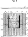
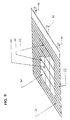
- FIGURES 1 and 8 show a top or perspective view of a roof or wall structure which is attached to or on a load-bearing part 10, e.g. a substructure or construction of a building is mounted.
- the load-bearing part 10 can be a post or transom of a supporting substructure of a roof.
- the structure comprises a multiplicity of insulation elements 20, which are preferably designed as sandwich composite elements.
- the sandwich composite element preferably has an outside, an inside and a foamed middle or core part (e.g. made of polyurethane), the outside and / or inside made of metal, e.g. Steel, copper or aluminum are formed and are particularly preferably foamed.
- the core part can also be formed from mineral wool or the like.
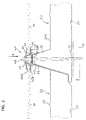
- Each insulation element 20 has one or more profile ribs 22 which project from the insulation element level 20A, preferably on one side opposite the substructure or the load-bearing part 10 (cf. in particular FIG. 2).
- the profile rib 22 preferably has a trapezoidal or polygonal cross-section and has an upper profile surface 22A, which runs essentially parallel to the insulation element plane 20A.
- the insulation element 20 can furthermore have one or more beads 24 and / or one or more beads or projections 25 for stiffening, which preferably run essentially parallel to the profile rib 22.
- An element joint 26 is also provided along a longitudinal joint of the insulating element 20, which preferably abuts a profile rib 22 of the adjacent insulating element 20 at least in regions.
- the element joint 22 can preferably be formed from the outside of the insulation element 20, ie for example that the outer cover shell is cantilevered or cranked and thus assumes a shape corresponding to the profile rib 22, for example in some areas.
- the element joint 26 preferably covers or projects above the upper profile surface 22A of the adjacent profile rib 22 (cf. FIG. 2).
- a sealing strip (not shown) can preferably be inserted between the element joint 26 and the upper profile surface 22A.
- Facade elements 30, in particular photovoltaic elements, are fastened to the profile rib 22, preferably on the upper profile surface 22A, by means of a holding device 40.
- the facade elements 30 are preferably spaced apart from the insulation element plane 20A, so that there is a cavity 60 to be described later between them.
- the holding device 40 comprises an up or contact profile 42, a pressure or clamping profile 44, between which the facade element 30 can be arranged or fastened or clamped.
- the contact profile 42 has a contact surface 42A and the clamping profile 44 has a clamping surface 44A, the contact surface 42A and the clamping surface 44A effecting the fastening of the facade element 30, whereby forces from loads on the facade element 30 (e.g. wind pressure and wind suction loads) over the surfaces 42A and 44A are transferred to the holding device 40.
- the contact profile 42 and the clamping profile 44 each have at least one alignment surface 43 or 45, which abut one another and prevent a relative displacement of the contact and clamping profiles 42 and 44 in the plane of the facade element 30 and only permit their displacement along a clamping direction A. This ensures that the facade element is securely clamped.
- Elastic elements 46 or 47 are preferably provided on the contact surface 42A and / or on the clamping surface 44A so as not to damage the facade elements 30 when clamping and to seal them off from the holding device 40.
- the holding device 40 further comprises a screw 48, which is preferably threadless in the screw head area.
- the screw 48 preferably projects through the insulating element 20 by means of a pilot hole and is fastened to the load-bearing part 10 (FIG. 2). Accordingly, the loads are derived from the facade element 30 on the substructure or the load-bearing part 10.
- a screw 48 ′ can be fastened to the insulating element 20 itself.
- a washer (not shown) can be placed under the screw 48, the washer preferably having a sealing member (e.g. vulcanized neoprene seal).
- a sealing fastening cap can also be provided.
- FIG. 4 shows an edge region of the roof or wall structure (section C-C in FIG. 1).
- a filler element or profile 49 is provided in the edge region at least in regions.
- the filling element 49 is arranged between the contact surfaces 42A, 44A of the contact profile 42 and the clamping profile 44, between which no facade element 30 is arranged.
- the filling element 49 ensures a reliable fastening of the structure by the holding device 40 in this edge region, in particular by the correct alignment and uniform arrangement of the contact surfaces 42A, 44A. Furthermore, the filling element 49 ensures that the holding device 40 is sealed in the edge region.
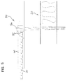
- FIG. 5 is a section along EE in FIG. 1, ie in an abutting area of the facade elements 30, which are arranged at an angle different from 0 ° and 180 °, preferably approximately 90 °, to the longitudinal direction of the holding device 40.
- a spacer profile or element 50 (in particular as an end profile) is preferably provided along this joint area.
- the spacer element 50 has projecting areas 52 which secure the facade element 30 in addition to the holding device 40 (in the pressure and / or suction direction).
- the spacer element 50 can comprise a screw 54, which is fastened to the insulating element 20 and / or in the load-bearing part 10 can, and ensures correct alignment of the facade elements to each other and / or their alignment with respect to the insulation elements 20, for example, to achieve a perfectly flat outside of the roof or wall structure.
- the spacer 50 does not always have to be fastened by means of the screw. However, it is preferred that the spacer element 50 serving as the end profile according to FIG. 5 screwed to better absorb the wind loads.
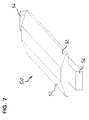
- the spacer 50 is preferably as shown in FIG. 7 trained.
- the spacer element 50 can have one or more clamping projections 56 which extend essentially in the longitudinal direction and which can be clamped between the contact profile 42 and the clamping profile 44 of the corresponding holding device. A simple and secure attachment of the spacer element 50 is thus provided.
- the end spacer 50 can, however, continue to be attached by means of a screw 54 as required.
- a cavity 60 between the photovoltaic element 30 and the insulation element is advantageous to provide a cavity 60 between the photovoltaic element 30 and the insulation element.
- the size of the cavity can be adjusted by means of the height of the profile rib 22.
- This cavity 60 can be used for rear ventilation behind the photovoltaic element 30 in order to produce a suitable temperature gradient or gradient in the photovoltaic element 30, as a result of which the efficiency of the photovoltaic cell can be improved.
- An air flow can be generated in this cavity 60 by a blower, fan or the like and / or by natural air convection. Natural air convection can be achieved in particular by a suitable inclination (for example greater than approximately 3 °, preferably greater than 5 ° from the horizontal) of the roof and / or wall structure.
- the exhaust air can also be used for energy generation by means of a heat exchanger or the like. If the waste heat is fully used, profiles (eg the spacer profiles 50) can be used to completely seal the flow areas of the cavity 60.
- the thermal Waste heat can be used in the building and / or air / water can be temporarily stored via a heat exchanger.
Landscapes
- Engineering & Computer Science (AREA)
- Architecture (AREA)
- Chemical & Material Sciences (AREA)
- Sustainable Development (AREA)
- Sustainable Energy (AREA)
- Thermal Sciences (AREA)
- Physics & Mathematics (AREA)
- Combustion & Propulsion (AREA)
- Mechanical Engineering (AREA)
- General Engineering & Computer Science (AREA)
- Life Sciences & Earth Sciences (AREA)
- Civil Engineering (AREA)
- Structural Engineering (AREA)
- Roof Covering Using Slabs Or Stiff Sheets (AREA)
Applications Claiming Priority (2)
| Application Number | Priority Date | Filing Date | Title |
|---|---|---|---|
| DE19802997 | 1998-01-27 | ||
| DE19802997A DE19802997A1 (de) | 1998-01-27 | 1998-01-27 | Dach- und/oder Wandaufbau sowie Verwendung hiervon |
Publications (1)
| Publication Number | Publication Date |
|---|---|
| EP0952616A2 true EP0952616A2 (fr) | 1999-10-27 |
Family
ID=7855770
Family Applications (1)
| Application Number | Title | Priority Date | Filing Date |
|---|---|---|---|
| EP99101504A Withdrawn EP0952616A2 (fr) | 1998-01-27 | 1999-01-27 | Structure de toit et/ou de paroi et son utilisation |
Country Status (2)
| Country | Link |
|---|---|
| EP (1) | EP0952616A2 (fr) |
| DE (1) | DE19802997A1 (fr) |
Cited By (1)
| Publication number | Priority date | Publication date | Assignee | Title |
|---|---|---|---|---|
| EP2144016A1 (fr) | 2008-07-07 | 2010-01-13 | Sol in G | Structure support de panneau solaire en surface de construction |
Families Citing this family (15)
| Publication number | Priority date | Publication date | Assignee | Title |
|---|---|---|---|---|
| DE10136037A1 (de) * | 2001-07-25 | 2003-03-13 | Ibc Solar Ag | Dachintegriertes Solarmodulsystem |
| DE202007018367U1 (de) | 2007-08-02 | 2008-07-03 | Niemetz Metall Gmbh | Gebäude-Paneele |
| ITUD20080146A1 (it) * | 2008-06-25 | 2009-12-26 | Breda Tecnologie Commerciali Srl | Pannello di copertura per il montaggio di moduli fotovoltaici e procedimento per realizzare tale pannello di copertura |
| DE102008031453A1 (de) * | 2008-07-05 | 2010-01-07 | Bernhard Dipl.-Ing. Heming | Sandwich-Fertigdachmodul für ein großflächiges Dach eines Bauwerks |
| ITMC20080228A1 (it) * | 2008-12-18 | 2010-06-19 | Alberto Ciucci | Sistema per il fissaggio di pannelli fotovoltaici o solari su coperture per tetti ottenute con elementi dotati di profilo grecato. |
| ITBO20090212A1 (it) * | 2009-04-01 | 2010-10-02 | Italpannelli S R L | Sistema per il fissaggio di unita' operative in particolare fotovoltaiche, ad una copertura costituita da pannelli isolanti |
| DE202009004746U1 (de) | 2009-04-28 | 2009-07-23 | Kumatec Sondermaschinenbau & Kunststoffverarbeitung Gmbh | Befestigungseinrichtung zum Fixieren eines Holmes oder einer Leiste an einem C-Profil |
| NL1037010C2 (en) * | 2009-06-03 | 2010-12-08 | Ecofys Netherlands B V | A method of mounting a multitude of devices for hanessing solar energy, a positioning body for use in said method, a clamp guiding body, and a prefab roof element. |
| IT1395216B1 (it) * | 2009-08-10 | 2012-09-05 | Emme Ci S R L | Struttura di copertura |
| ITAP20090004A1 (it) * | 2009-10-07 | 2011-04-08 | Energy Resources Srl | Profilo longitudinale predisposto per lã ⠬⠢applicazione su lamiera grecata o pannello sandwich |
| IT1396109B1 (it) * | 2009-10-07 | 2012-11-16 | Energy Resources Srl | Morsetto per il fissaggio di moduli fotovoltaici privi di cornice. |
| DE202010008389U1 (de) | 2010-08-27 | 2010-11-11 | Ibc Solar Ag | Vorrichtung zum Befestigen einer Tragschiene |
| DE102011102839A1 (de) * | 2011-05-30 | 2012-12-06 | Helmut Ott | Sandwichelement und Gebäude in Sandwichbauweise |
| US10547270B2 (en) | 2016-02-12 | 2020-01-28 | Solarcity Corporation | Building integrated photovoltaic roofing assemblies and associated systems and methods |
| DE102023001672A1 (de) | 2023-04-14 | 2024-10-17 | Robert Vögele | Multifunktionale Wand- und Dacheindeckung zum Schutz des Gebäudes gegen jegliche Witterungseinflüsse, zur optimalen Gewinnung von Solarstrom und/oder Solarthermie, und/oder Solarwärme (Luft), mit luft- und wasserdichter Abdichtung der einzelnen Module, wahlweise mit integrierter Wärmedämmung |
Family Cites Families (2)
| Publication number | Priority date | Publication date | Assignee | Title |
|---|---|---|---|---|
| CA1092462A (fr) * | 1977-06-20 | 1980-12-30 | Peter J. Hastwell | No translation available |
| FR2469673A1 (fr) * | 1979-11-15 | 1981-05-22 | Usinor | Element de construction formant capteur d'energie solaire |
-
1998
- 1998-01-27 DE DE19802997A patent/DE19802997A1/de not_active Ceased
-
1999
- 1999-01-27 EP EP99101504A patent/EP0952616A2/fr not_active Withdrawn
Non-Patent Citations (1)
| Title |
|---|
| None |
Cited By (1)
| Publication number | Priority date | Publication date | Assignee | Title |
|---|---|---|---|---|
| EP2144016A1 (fr) | 2008-07-07 | 2010-01-13 | Sol in G | Structure support de panneau solaire en surface de construction |
Also Published As
| Publication number | Publication date |
|---|---|
| DE19802997A1 (de) | 1999-08-05 |
Similar Documents
| Publication | Publication Date | Title |
|---|---|---|
| DE10132557C2 (de) | Montageprofil zur Befestigung von Photovoltaik-Modulen und Montagesystem | |
| DE19802997A1 (de) | Dach- und/oder Wandaufbau sowie Verwendung hiervon | |
| WO2007096157A2 (fr) | Système de module solaire comportant une structure porteuse | |
| WO2011138344A2 (fr) | Sous-structure pour installation solaire | |
| DE4444439A1 (de) | Solarenergieanlage sowie Montageelement dafür | |
| EP2140499A1 (fr) | Module solaire pour toit pentu | |
| DE102006009194A1 (de) | Anordnung aus einer tragenden Gebäudestruktur und einem Solarzellenaufbau | |
| DE202012005162U1 (de) | Rahmenteil für plattenförmige Funktionselemente und Abdeckungs-System gebildet aus einer Vielzahl derartiger Funktionselemente | |
| DE102011104516A1 (de) | Rahmen für plattenförmige Funktionselemente, Indachsystem gebildet aus einer Vielzahl derartiger Funktionselemente sowie Installationsverfahren hierfür | |
| DE102009043810A1 (de) | Befestigungssystem und Dachaufbau | |
| EP2190030A2 (fr) | Unité photovoltaïque, système photovoltaïque ainsi que procédé de fabrication d'une unité photovoltaïque | |
| EP1988227B1 (fr) | Toit pour bâtiments | |
| DE202008004055U1 (de) | Dachmodul für Solaranwendungen | |
| DE102008055953A1 (de) | Integriertes Dachsystem, Befestigung von Einlegeprofilen auf Sandwichpaneelen mit Hinterschnitt-Nuten | |
| DE102005053639B4 (de) | Befestigungssystem für Solarmodule | |
| EP2528107A1 (fr) | Elément de façade | |
| CH707930B1 (de) | Fassaden- oder Dachelement, aufweisend eine oder mehrere photovoltaische Solarzellen. | |
| DE102008008923B4 (de) | Leicht handhabbares Gestell für Dachaufbauten an Flachdächern und geneigten Flachdächern | |
| EP0674141A2 (fr) | Panneau pour collecteur solaire | |
| CH705987A1 (de) | Gebäudeintegriertes Photovoltaik Rahmensystem. | |
| DE202024100335U1 (de) | Montagesystem für Photovoltaik-Module und andere flächige Elemente | |
| DE102009056337A1 (de) | Montagesystem für Solarmodule sowie Sonnenenergieanlage mit dem Montagesystem | |
| DE3048113A1 (de) | Baukonstruktionselement sowie damit hergestelltes energie- oder absorberdach bzw. energie- oder absorberfassade | |
| DE102007014165A1 (de) | Halteelement, Verfahren zum Befestigen eines Halteelementes auf einer Dachfläche und System zur Befestigung von Platten auf einem Dach mit einem entsprechenden Halteelement | |
| DE10309445B3 (de) | Rahmensystem für Dachbauelemente |
Legal Events
| Date | Code | Title | Description |
|---|---|---|---|
| PUAI | Public reference made under article 153(3) epc to a published international application that has entered the european phase |
Free format text: ORIGINAL CODE: 0009012 |
|
| AK | Designated contracting states |
Kind code of ref document: A2 Designated state(s): AT BE CH CY DE DK ES FI FR GB GR IE IT LI LU MC NL PT SE |
|
| AX | Request for extension of the european patent |
Free format text: AL;LT;LV;MK;RO;SI |
|
| STAA | Information on the status of an ep patent application or granted ep patent |
Free format text: STATUS: THE APPLICATION IS DEEMED TO BE WITHDRAWN |
|
| 18D | Application deemed to be withdrawn |
Effective date: 20010801 |