EP0952626B1 - Connecteur - Google Patents
Connecteur Download PDFInfo
- Publication number
- EP0952626B1 EP0952626B1 EP99106778A EP99106778A EP0952626B1 EP 0952626 B1 EP0952626 B1 EP 0952626B1 EP 99106778 A EP99106778 A EP 99106778A EP 99106778 A EP99106778 A EP 99106778A EP 0952626 B1 EP0952626 B1 EP 0952626B1
- Authority
- EP
- European Patent Office
- Prior art keywords
- plug connector
- plug
- connector according
- ducts
- conductor
- Prior art date
- Legal status (The legal status is an assumption and is not a legal conclusion. Google has not performed a legal analysis and makes no representation as to the accuracy of the status listed.)
- Expired - Lifetime
Links
- 239000004020 conductor Substances 0.000 claims description 32
- 238000003780 insertion Methods 0.000 claims description 31
- 230000037431 insertion Effects 0.000 claims description 31
- 238000010276 construction Methods 0.000 claims description 2
- 239000002184 metal Substances 0.000 claims 1
- 238000012216 screening Methods 0.000 claims 1
- 230000005540 biological transmission Effects 0.000 description 1
- 238000005520 cutting process Methods 0.000 description 1
- 230000000694 effects Effects 0.000 description 1
- 238000004519 manufacturing process Methods 0.000 description 1
- 238000000034 method Methods 0.000 description 1
- 238000009740 moulding (composite fabrication) Methods 0.000 description 1
- BASFCYQUMIYNBI-UHFFFAOYSA-N platinum Chemical compound [Pt] BASFCYQUMIYNBI-UHFFFAOYSA-N 0.000 description 1
- 238000003825 pressing Methods 0.000 description 1
- 238000007493 shaping process Methods 0.000 description 1
- 230000008054 signal transmission Effects 0.000 description 1
- 238000003466 welding Methods 0.000 description 1
Images




Classifications
-
- H—ELECTRICITY
- H01—ELECTRIC ELEMENTS
- H01R—ELECTRICALLY-CONDUCTIVE CONNECTIONS; STRUCTURAL ASSOCIATIONS OF A PLURALITY OF MUTUALLY-INSULATED ELECTRICAL CONNECTING ELEMENTS; COUPLING DEVICES; CURRENT COLLECTORS
- H01R24/00—Two-part coupling devices, or either of their cooperating parts, characterised by their overall structure
- H01R24/38—Two-part coupling devices, or either of their cooperating parts, characterised by their overall structure having concentrically or coaxially arranged contacts
- H01R24/40—Two-part coupling devices, or either of their cooperating parts, characterised by their overall structure having concentrically or coaxially arranged contacts specially adapted for high frequency
- H01R24/50—Two-part coupling devices, or either of their cooperating parts, characterised by their overall structure having concentrically or coaxially arranged contacts specially adapted for high frequency mounted on a PCB [Printed Circuit Board]
-
- H—ELECTRICITY
- H01—ELECTRIC ELEMENTS
- H01R—ELECTRICALLY-CONDUCTIVE CONNECTIONS; STRUCTURAL ASSOCIATIONS OF A PLURALITY OF MUTUALLY-INSULATED ELECTRICAL CONNECTING ELEMENTS; COUPLING DEVICES; CURRENT COLLECTORS
- H01R12/00—Structural associations of a plurality of mutually-insulated electrical connecting elements, specially adapted for printed circuits, e.g. printed circuit boards [PCB], flat or ribbon cables, or like generally planar structures, e.g. terminal strips, terminal blocks; Coupling devices specially adapted for printed circuits, flat or ribbon cables, or like generally planar structures; Terminals specially adapted for contact with, or insertion into, printed circuits, flat or ribbon cables, or like generally planar structures
- H01R12/70—Coupling devices
- H01R12/71—Coupling devices for rigid printing circuits or like structures
- H01R12/712—Coupling devices for rigid printing circuits or like structures co-operating with the surface of the printed circuit or with a coupling device exclusively provided on the surface of the printed circuit
- H01R12/716—Coupling device provided on the PCB
-
- H—ELECTRICITY
- H01—ELECTRIC ELEMENTS
- H01R—ELECTRICALLY-CONDUCTIVE CONNECTIONS; STRUCTURAL ASSOCIATIONS OF A PLURALITY OF MUTUALLY-INSULATED ELECTRICAL CONNECTING ELEMENTS; COUPLING DEVICES; CURRENT COLLECTORS
- H01R13/00—Details of coupling devices of the kinds covered by groups H01R12/70 or H01R24/00 - H01R33/00
- H01R13/73—Means for mounting coupling parts to apparatus or structures, e.g. to a wall
- H01R13/74—Means for mounting coupling parts in openings of a panel
-
- H—ELECTRICITY
- H01—ELECTRIC ELEMENTS
- H01R—ELECTRICALLY-CONDUCTIVE CONNECTIONS; STRUCTURAL ASSOCIATIONS OF A PLURALITY OF MUTUALLY-INSULATED ELECTRICAL CONNECTING ELEMENTS; COUPLING DEVICES; CURRENT COLLECTORS
- H01R2103/00—Two poles
-
- H—ELECTRICITY
- H01—ELECTRIC ELEMENTS
- H01R—ELECTRICALLY-CONDUCTIVE CONNECTIONS; STRUCTURAL ASSOCIATIONS OF A PLURALITY OF MUTUALLY-INSULATED ELECTRICAL CONNECTING ELEMENTS; COUPLING DEVICES; CURRENT COLLECTORS
- H01R4/00—Electrically-conductive connections between two or more conductive members in direct contact, i.e. touching one another; Means for effecting or maintaining such contact; Electrically-conductive connections having two or more spaced connecting locations for conductors and using contact members penetrating insulation
- H01R4/24—Connections using contact members penetrating or cutting insulation or cable strands
-
- H—ELECTRICITY
- H01—ELECTRIC ELEMENTS
- H01R—ELECTRICALLY-CONDUCTIVE CONNECTIONS; STRUCTURAL ASSOCIATIONS OF A PLURALITY OF MUTUALLY-INSULATED ELECTRICAL CONNECTING ELEMENTS; COUPLING DEVICES; CURRENT COLLECTORS
- H01R4/00—Electrically-conductive connections between two or more conductive members in direct contact, i.e. touching one another; Means for effecting or maintaining such contact; Electrically-conductive connections having two or more spaced connecting locations for conductors and using contact members penetrating insulation
- H01R4/28—Clamped connections, spring connections
- H01R4/50—Clamped connections, spring connections utilising a cam, wedge, cone or ball also combined with a screw
- H01R4/5033—Clamped connections, spring connections utilising a cam, wedge, cone or ball also combined with a screw using wedge or pin penetrating into the end of a wire in axial direction of the wire
Definitions
- the invention relates to a connector for electrically conductive Connection of conductor tracks of a circuit board with at least one coaxial cable according to the preamble of claim 1.
- Such connectors are used to transmit High-frequency signals between a circuit board and a board contacting it Allow cables.
- A is a connector for connecting a coaxial cable known in the case of vertically cutting slot recesses contacts are provided in an insertion channel that is gradually narrowed are.
- a central manager is contacted through one of the contacts and the outer shield of the conductor contacts the other contacts.
- US Pat. No. 4,533,191 A discloses a plug connector with an insertion channel, for connecting conductor tracks of a circuit board with a Coaxial cable, known.
- slot recesses that the Cut the insertion channel and are inserted into the plug contacts.
- the invention solves this problem with a connector with the Features of claim 1.
- this can Insert parallel insertion channels that are parallel without one Kinks in their course and perpendicular to their course are reliably contacted by inserted plug contacts.
- the construction height the connector can be kept very low; the The connector in the exemplary embodiment has a height of approximately 7 mm.
- the contacting is particularly reliable if for shielding one Coaxial cable two plug contacts are provided in this shield cut in, and another plug contact for the central conductor is provided.
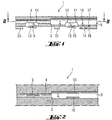
- the connector 1,101 shown in the drawing has in its middle area several adjacent insertion channels 2 for Coaxial cables, each of which has a gradation 3 over its longitudinal course, the one front end region 4 for receiving the central inner conductor of the coaxial cable from a rear end region 5 for receiving of the coaxial cable with inner conductor and outer shield.
- the front end region 4 has one opposite the rear end region 5 reduced diameter, such that this the diameter of the Shield falls below, so that the shield from the coaxial cable be removed at least over the length of the front end region 4 got to.
- slot recesses 6,7,8 provided, which are designed to accommodate plug contacts 9,10 are.
- the two rear slot recesses 7 are arranged in such a way that the plug contacts 10 to be inserted there shield cut the coaxial cable essentially tangentially.
- the coaxial cables are first contacted after partial removal the shield inserted into the insertion channel 2, then the Plug contacts 9,10 pressed into the slot recesses 6,7, whereby the respective conductors cut and thus conductive with the plug contacts 9,10 can be connected.
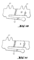
- the plug contacts 9, 10 each at least one tip 11.
- the Plug contacts 9, 10 are provided with spring clips 12, which on the respective conductor track 23, 24, 25 of the circuit board 21 exert a pressure which is reliable Contacting ensures.
- the plug contacts 9, 10 for the inner conductor or the shield is of the same design, so that only the provision for this a component type is required.
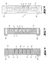
- the connector 1 has coaxial cables in its outer areas in the level of the insertion channels 2 on three further line channels 13 Take up single-core cables, for example for power supply or for transmission of a low-frequency signal.
- the other line channels 13 are symmetrical to the insertion channels 2 and have also via slot recesses 8, which are used to insert plug contacts are provided. These can be used in the same way as the others Plug contacts 9,10 be formed.
- strain reliefs in the rear area of the connector 14.15 are strain reliefs in the rear area of the connector 14.15 provided.
- the strain relief 14 or 15 each integrally formed with the housing and can be a Film hinge 16 are pivoted into a closed position in the it is fixed behind a counter edge 17 and with a tip 18 Cable holds non-positively in the respective channel 2.13. Because of the one-piece design with the housing is such a strain relief 14.15 in Manufacturing particularly inexpensive.
- a comb 19 When transmitting high-frequency signals, especially in the range of A comb 19 is provided for frequencies greater than 1 GHz, which is made of electrically conductive material and the insertion channels 2 separates from each other, so that a signal transmission between to prevent the coaxial conductors.
- the connector 1,101 has lugs 20 on the underside, which around the Grip area of a board 21 and thereby the connector 1 the board 21 hold.
- the circuit board can have lugs 22 which have a stop represent 1.1101 for the push-on connector.
- the conductor tracks 23,24,25 of the board that is in contact with the connector 1,101 stand, are adapted to the corresponding arrangement of the connectors; So there are two conductor tracks 24 for contacting the shield symmetrical to a central conductor track 25 for contacting the inner conductor.
- Three conductor tracks 23 each run in the outer region for the low-frequency individual conductors or those transmitting a direct voltage, which are inserted into the line channels 13.
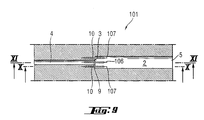
- the three plug contacts 9, 10 are arranged next to one another at an axial height of the plug connector 101.
- the middle plug contact 9 contacts the central conductor in the front area 4 of the insertion channel 2, while the outer plug contacts 10 contact the outer shield in the rear area 5 of the insertion channel 2.
- This position of the plug contacts 9, 10 next to one another improves the shielding behavior
- the outer plug contacts 10 have contact tips 11 which extend into the expanded area of the insertion channel 2, so that the outer shield of the pressed-in cable can be cut and contacted here.
- the tips 11 assigned to the narrower area 4 of the insertion channel 2 have no contact effect since they lie next to the inner conductor. These tips 11 could also be removed.
- FIG. 12 is a connector 201 with a modified strain relief 214, which is essentially like that shown in FIG. 1 and connector described above is formed.
- the strain relief However, it is designed so that the conclusion in the pivoted state of the connector housing.
- FIG. 12 shows a section through the plug connector with the insertion channel 202, which in the rear, expanded area 205 and front area 204 is divided.
- the conically shaped pins 226 are horizontally arranged side by side so that when closing the strain relief in each case in spaces the cable or coaxial cable are pushed and due to the oblique Shaping the cables clamp the spacing and size of the tapered pins 226 to the different diameters of the Coaxial cable and the single conductor are adapted.
Landscapes
- Coupling Device And Connection With Printed Circuit (AREA)
- Details Of Connecting Devices For Male And Female Coupling (AREA)
- Earth Drilling (AREA)
- Piezo-Electric Or Mechanical Vibrators, Or Delay Or Filter Circuits (AREA)
- Quick-Acting Or Multi-Walled Pipe Joints (AREA)
Claims (10)
- Connecteur à fiches (1), (101) pour la connexion électrique de circuits conducteurs (24), (25) de plaquettes à circuit imprimé (21) avec au moins un câble coaxial pourvu d'un blindage extérieur, ledit connecteur à fiches (1), (101) comportant au moins un canal d'enfichage (2) pour le câble coaxial, caractérisé en ce quele canal d'enfichage (2) comporte un étagement (3) longitudinal dont la zone d'extrémité avant (4) présente une section transversale réduite, inférieure au diamètre du blindage,il est prévu des fentes (6,7), (106,107) destinées aux contacts à fiches (9), (10) coupant le canal d'enfichage perpendiculairement,il est prévu trois fentes (6,7), (106,107) avec des contacts à fiches (9), (10) pour un câble coaxial, l'un des contact à fiches (9) assurant la connexion du conducteur central dans la zone avant (4) du canal d'enfichage (2), les deux autres contacts à fiches (10) assurant la connexion du blindage extérieur dans la zone arrière (5) du canal d'enfichage (2),les contacts à fiches (9), (10) comportent au moins une pointe (11) pour la connexion du câble et une bride de ressort (12) faisant face à ladite pointe (11), en vue de son application sur un circuit conducteur (23), (24), (25) de la plaquette à circuit imprimé (21).
- Connecteur à fiches selon la revendication 1 caractérisé en ce que le connecteur à fiches (1), (101) comporte dans sa zone arrière une décharge de traction (14), (15) assemblée avec une charnière film (16) et pivotant autour de cette dernière.
- Connecteur à fiches selon la revendication 2 caractérisé en ce que la décharge de traction (214) est pourvue de pointes (226) de forme conique s'engageant après pivotement de la décharge de traction (214) dans des évidements (227).
- Connecteur à fiches selon la revendication 3 caractérisé en ce que les pointes (226) de forme conique peuvent être soudées dans les évidements (227).
- Connecteur à fiches selon l'une des revendications 1 à 4 caractérisé en ce que les contacts à fiches (9), (10) pour le conducteur intérieur et le blindage sont identiques.
- Connecteur à fiches selon l'une des revendications 1 à 4 caractérisé en ce que le connecteur à fiches (1), (101) comporte au moins un autre canal de connexion (13) pour un conducteur individuel, qui est parallèle au canaux d'enfichage (2) pour les câbles coaxiaux et qui est pourvu, par l'intermédiaire d'une fente (8), d'un contact à fiches.
- Connecteur à fiches selon la revendication 6 caractérisé en ce que les canaux de connexion (13) pour les conducteurs individuels sont disposés dans la zone des bords du connecteur à fiches (1), (101) et comportent une décharge de traction (14) propre, séparée de la décharge de traction (15) du ou des câble(s) coaxial/aux.
- Connecteur à fiches selon l'une des revendications 1 à 7 caractérisé en ce que il est prévu plusieurs canaux d'enfichage (2) pour des câbles coaxiaux, qui sont séparés les uns des autres par un peigne de blindage (19).
- Connecteur à fiches selon l'une des revendications 1 à 8 caractérisé en ce que le connecteur à fiches (1), (101) comporte dans sa partie médiane quatre canaux d'enfichage (2) pour des câbles coaxiaux et, dans la zone des bords, trois canaux de connexion (13) pour des conducteurs électriques individuels, symétriques aux canaux d'enfichage.
- Connecteur à fiches selon l'une des revendications 1 à 9 caractérisé en ce que les fentes (6), (7), (8) pour les contacts à fiches (9), (10) des canaux d'enfichage sont disposées dans un même plan.
Applications Claiming Priority (2)
| Application Number | Priority Date | Filing Date | Title |
|---|---|---|---|
| DE29807349U DE29807349U1 (de) | 1998-04-24 | 1998-04-24 | Steckverbinder |
| DE29807349U | 1998-04-24 |
Publications (2)
| Publication Number | Publication Date |
|---|---|
| EP0952626A1 EP0952626A1 (fr) | 1999-10-27 |
| EP0952626B1 true EP0952626B1 (fr) | 2002-01-09 |
Family
ID=8056182
Family Applications (1)
| Application Number | Title | Priority Date | Filing Date |
|---|---|---|---|
| EP99106778A Expired - Lifetime EP0952626B1 (fr) | 1998-04-24 | 1999-04-06 | Connecteur |
Country Status (3)
| Country | Link |
|---|---|
| US (1) | US6120314A (fr) |
| EP (1) | EP0952626B1 (fr) |
| DE (2) | DE29807349U1 (fr) |
Cited By (1)
| Publication number | Priority date | Publication date | Assignee | Title |
|---|---|---|---|---|
| DE102004032006B3 (de) * | 2004-07-01 | 2006-04-20 | Kathrein-Werke Kg | Kontaktelement |
Families Citing this family (5)
| Publication number | Priority date | Publication date | Assignee | Title |
|---|---|---|---|---|
| DE10048505A1 (de) * | 2000-09-29 | 2002-04-11 | Reitter & Schefenacker Gmbh | Steckverbindungseinrichtung, vorzugsweise für Außenstückblickspiegel von Kraftfahrzeugen |
| US6802739B2 (en) * | 2003-01-16 | 2004-10-12 | Corning Gilbert Inc. | Coaxial cable connector |
| DE102009046601A1 (de) | 2009-11-11 | 2011-06-09 | Robert Bosch Gmbh | Leiterplattenanordnung |
| US9142924B2 (en) * | 2012-08-23 | 2015-09-22 | Zierick Manufacturing Corp. | Surface mount coaxial cable connector |
| CN107732471B (zh) * | 2017-12-09 | 2019-12-13 | 广东电网有限责任公司电力科学研究院 | 一种电力线缆连接穿刺线鼻子 |
Family Cites Families (14)
| Publication number | Priority date | Publication date | Assignee | Title |
|---|---|---|---|---|
| GB960291A (en) * | 1962-05-08 | 1964-06-10 | Amp Inc | Electrical connector for connecting a lead to the braid of a braid-shielded cable |
| DE1928485A1 (de) * | 1969-06-04 | 1970-12-10 | Siemens Ag | Vorrichtung zum Anschluss und zur Klemmung des Innenleiters und des Aussenleiters eines Koaxialkabels |
| US3915535A (en) | 1974-02-21 | 1975-10-28 | Amp Inc | Coaxial cable receptacle for printed circuit boards |
| US4261632A (en) * | 1979-04-09 | 1981-04-14 | Thomas & Betts Corporation | Coaxial cable connector |
| DE3333973A1 (de) | 1983-09-20 | 1985-04-04 | Siemens AG, 1000 Berlin und 8000 München | Kontaktklemme fuer leiterplatten |
| US4533191A (en) * | 1983-11-21 | 1985-08-06 | Burndy Corporation | IDC termination having means to adapt to various conductor sizes |
| NL8600041A (nl) * | 1985-12-23 | 1987-07-16 | Du Pont Nederland | Contactinrichting voor een afgeschermde kabel. |
| JP2906469B2 (ja) * | 1989-08-20 | 1999-06-21 | オムロン株式会社 | シールド線用コネクタ |
| US5147215A (en) * | 1990-03-08 | 1992-09-15 | Amp Incorporated | Connector with integral wire management system |
| US5199896A (en) * | 1991-07-29 | 1993-04-06 | Itt Corporation | Latchable p.c. board connector |
| US5437562A (en) * | 1993-03-26 | 1995-08-01 | The Whitaker Corporation | Low profile edge mount connector |
| US5505638A (en) * | 1994-11-18 | 1996-04-09 | Su; Gorden | Telephone plug module |
| US5664968A (en) | 1996-03-29 | 1997-09-09 | The Whitaker Corporation | Connector assembly with shielded modules |
| DE29622055U1 (de) | 1996-12-19 | 1997-03-06 | Albert Ackermann GmbH & Co. KG, 51643 Gummersbach | Steckverbinder für gedruckte Schaltungen |
-
1998
- 1998-04-24 DE DE29807349U patent/DE29807349U1/de not_active Expired - Lifetime
-
1999
- 1999-04-06 EP EP99106778A patent/EP0952626B1/fr not_active Expired - Lifetime
- 1999-04-06 DE DE59900733T patent/DE59900733D1/de not_active Expired - Fee Related
- 1999-04-22 US US09/299,552 patent/US6120314A/en not_active Expired - Fee Related
Cited By (1)
| Publication number | Priority date | Publication date | Assignee | Title |
|---|---|---|---|---|
| DE102004032006B3 (de) * | 2004-07-01 | 2006-04-20 | Kathrein-Werke Kg | Kontaktelement |
Also Published As
| Publication number | Publication date |
|---|---|
| DE29807349U1 (de) | 1998-06-18 |
| EP0952626A1 (fr) | 1999-10-27 |
| DE59900733D1 (de) | 2002-02-28 |
| US6120314A (en) | 2000-09-19 |
Similar Documents
| Publication | Publication Date | Title |
|---|---|---|
| DE102013110082B4 (de) | Steckverbinder | |
| DE3688284T2 (de) | Verbinder für ein Koaxialkabel. | |
| EP2466697B1 (fr) | Module de raccordement de câble de données et procédé destiné à sa confection sur un câble | |
| EP2797175B1 (fr) | Fiche pour un câble de données et/ou de télécommunications multi-brins | |
| DE2700197A1 (de) | Elektrischer steckverbinder | |
| DE3541772A1 (de) | Aufnahmeteil fuer elektrische steckverbinder | |
| DE3789969T2 (de) | Abgeschirmter kabelendstückeinbau. | |
| EP2026417B1 (fr) | Connecteur électrique doté d'éléments de contact hermaphrodites | |
| DD284782A5 (de) | Kontaktelement fuer elektrische leiter | |
| DE2735838C2 (de) | Elektrische Anschlußklemme und elektrisches Kabelverbindungsglied | |
| DE69522300T2 (de) | Modulstecker für Hochgeschwindigkeits-Datentransfer | |
| DE2855742C2 (de) | Kontaktelement für selbsttätig abisolierende Verbindungseinrichtung und mit diesem Kontaktelement ausgerüstete Verbindungseinrichtung | |
| EP0793299A1 (fr) | Connecteur coaxial | |
| DE10008932A1 (de) | Elektrischer Stecker | |
| EP2856558A1 (fr) | Fiche rj45 à dispositif de guidage pour brins | |
| DE69303490T2 (de) | Elektrischer verbinder | |
| EP1467441A2 (fr) | Connecteur pour un branchement rapide à technique de pince de serrage | |
| DE2406417A1 (de) | Elektrischer verbinder zur verbindung eines koaxialkabels mit einer gedruckten schaltungsplatte | |
| EP0945929B1 (fr) | Connecteur pour un câble blindé | |
| EP0952626A1 (fr) | Connecteur | |
| DE29804836U1 (de) | Steckverbinder für ein geschirmtes Kabel | |
| EP4386993A1 (fr) | Boîte de raccordement pour un réseau de données et de communication | |
| DE10323616A1 (de) | Schnellanschließbare Steckverbindung in Spannzangentechnik | |
| DE2339800B1 (de) | Huelsenfoermiges Klemmelement zum abisolierfreien Anschluss elektrischer Leiter | |
| DE202023102533U1 (de) | Kabelhalteelement, Kabelhaltevorrichtung, die das Kabelhalteelement umfasst und Kabelsteckverbindervorrichtung, die die Kabelhaltevorrichtung umfasst |
Legal Events
| Date | Code | Title | Description |
|---|---|---|---|
| PUAI | Public reference made under article 153(3) epc to a published international application that has entered the european phase |
Free format text: ORIGINAL CODE: 0009012 |
|
| AK | Designated contracting states |
Kind code of ref document: A1 Designated state(s): DE FR GB |
|
| AX | Request for extension of the european patent |
Free format text: AL;LT;LV;MK;RO;SI |
|
| 17P | Request for examination filed |
Effective date: 19991217 |
|
| 17Q | First examination report despatched |
Effective date: 20000419 |
|
| AKX | Designation fees paid |
Free format text: DE FR GB |
|
| GRAG | Despatch of communication of intention to grant |
Free format text: ORIGINAL CODE: EPIDOS AGRA |
|
| GRAG | Despatch of communication of intention to grant |
Free format text: ORIGINAL CODE: EPIDOS AGRA |
|
| GRAH | Despatch of communication of intention to grant a patent |
Free format text: ORIGINAL CODE: EPIDOS IGRA |
|
| GRAH | Despatch of communication of intention to grant a patent |
Free format text: ORIGINAL CODE: EPIDOS IGRA |
|
| GRAA | (expected) grant |
Free format text: ORIGINAL CODE: 0009210 |
|
| REG | Reference to a national code |
Ref country code: GB Ref legal event code: IF02 |
|
| AK | Designated contracting states |
Kind code of ref document: B1 Designated state(s): DE FR GB |
|
| REF | Corresponds to: |
Ref document number: 59900733 Country of ref document: DE Date of ref document: 20020228 |
|
| GBT | Gb: translation of ep patent filed (gb section 77(6)(a)/1977) |
Effective date: 20020406 |
|
| ET | Fr: translation filed | ||
| PLBE | No opposition filed within time limit |
Free format text: ORIGINAL CODE: 0009261 |
|
| STAA | Information on the status of an ep patent application or granted ep patent |
Free format text: STATUS: NO OPPOSITION FILED WITHIN TIME LIMIT |
|
| 26N | No opposition filed | ||
| PGFP | Annual fee paid to national office [announced via postgrant information from national office to epo] |
Ref country code: GB Payment date: 20030325 Year of fee payment: 5 |
|
| PGFP | Annual fee paid to national office [announced via postgrant information from national office to epo] |
Ref country code: FR Payment date: 20030417 Year of fee payment: 5 |
|
| PGFP | Annual fee paid to national office [announced via postgrant information from national office to epo] |
Ref country code: DE Payment date: 20030429 Year of fee payment: 5 |
|
| PG25 | Lapsed in a contracting state [announced via postgrant information from national office to epo] |
Ref country code: GB Free format text: LAPSE BECAUSE OF NON-PAYMENT OF DUE FEES Effective date: 20040406 |
|
| PG25 | Lapsed in a contracting state [announced via postgrant information from national office to epo] |
Ref country code: DE Free format text: LAPSE BECAUSE OF NON-PAYMENT OF DUE FEES Effective date: 20041103 |
|
| GBPC | Gb: european patent ceased through non-payment of renewal fee | ||
| PG25 | Lapsed in a contracting state [announced via postgrant information from national office to epo] |
Ref country code: FR Free format text: LAPSE BECAUSE OF NON-PAYMENT OF DUE FEES Effective date: 20041231 |
|
| REG | Reference to a national code |
Ref country code: FR Ref legal event code: ST |