EP0952629B1 - Elektrischer Steckverbinder für flexible Flachband-Schaltkreise - Google Patents
Elektrischer Steckverbinder für flexible Flachband-Schaltkreise Download PDFInfo
- Publication number
- EP0952629B1 EP0952629B1 EP99107146A EP99107146A EP0952629B1 EP 0952629 B1 EP0952629 B1 EP 0952629B1 EP 99107146 A EP99107146 A EP 99107146A EP 99107146 A EP99107146 A EP 99107146A EP 0952629 B1 EP0952629 B1 EP 0952629B1
- Authority
- EP
- European Patent Office
- Prior art keywords
- connector
- body member
- flexible circuit
- resilient
- locating
- Prior art date
- Legal status (The legal status is an assumption and is not a legal conclusion. Google has not performed a legal analysis and makes no representation as to the accuracy of the status listed.)
- Expired - Lifetime
Links
- 239000004020 conductor Substances 0.000 claims description 18
- 230000000295 complement effect Effects 0.000 claims description 9
- 239000013536 elastomeric material Substances 0.000 claims description 8
- 230000013011 mating Effects 0.000 claims description 8
- 239000004033 plastic Substances 0.000 claims description 8
- 229920002379 silicone rubber Polymers 0.000 claims description 7
- 239000004945 silicone rubber Substances 0.000 claims description 7
- 239000000463 material Substances 0.000 claims description 4
- 239000003989 dielectric material Substances 0.000 description 2
- 239000011241 protective layer Substances 0.000 description 2
- 206010035148 Plague Diseases 0.000 description 1
- 241000607479 Yersinia pestis Species 0.000 description 1
- 239000013070 direct material Substances 0.000 description 1
- 230000037431 insertion Effects 0.000 description 1
- 238000003780 insertion Methods 0.000 description 1
- 239000000758 substrate Substances 0.000 description 1
Images



Classifications
-
- H—ELECTRICITY
- H01—ELECTRIC ELEMENTS
- H01R—ELECTRICALLY-CONDUCTIVE CONNECTIONS; STRUCTURAL ASSOCIATIONS OF A PLURALITY OF MUTUALLY-INSULATED ELECTRICAL CONNECTING ELEMENTS; COUPLING DEVICES; CURRENT COLLECTORS
- H01R9/00—Structural associations of a plurality of mutually-insulated electrical connecting elements, e.g. terminal strips or terminal blocks; Terminals or binding posts mounted upon a base or in a case; Bases therefor
-
- H—ELECTRICITY
- H01—ELECTRIC ELEMENTS
- H01R—ELECTRICALLY-CONDUCTIVE CONNECTIONS; STRUCTURAL ASSOCIATIONS OF A PLURALITY OF MUTUALLY-INSULATED ELECTRICAL CONNECTING ELEMENTS; COUPLING DEVICES; CURRENT COLLECTORS
- H01R12/00—Structural associations of a plurality of mutually-insulated electrical connecting elements, specially adapted for printed circuits, e.g. printed circuit boards [PCB], flat or ribbon cables, or like generally planar structures, e.g. terminal strips, terminal blocks; Coupling devices specially adapted for printed circuits, flat or ribbon cables, or like generally planar structures; Terminals specially adapted for contact with, or insertion into, printed circuits, flat or ribbon cables, or like generally planar structures
- H01R12/70—Coupling devices
- H01R12/77—Coupling devices for flexible printed circuits, flat or ribbon cables or like structures
- H01R12/79—Coupling devices for flexible printed circuits, flat or ribbon cables or like structures connecting to rigid printed circuits or like structures
-
- H—ELECTRICITY
- H01—ELECTRIC ELEMENTS
- H01R—ELECTRICALLY-CONDUCTIVE CONNECTIONS; STRUCTURAL ASSOCIATIONS OF A PLURALITY OF MUTUALLY-INSULATED ELECTRICAL CONNECTING ELEMENTS; COUPLING DEVICES; CURRENT COLLECTORS
- H01R12/00—Structural associations of a plurality of mutually-insulated electrical connecting elements, specially adapted for printed circuits, e.g. printed circuit boards [PCB], flat or ribbon cables, or like generally planar structures, e.g. terminal strips, terminal blocks; Coupling devices specially adapted for printed circuits, flat or ribbon cables, or like generally planar structures; Terminals specially adapted for contact with, or insertion into, printed circuits, flat or ribbon cables, or like generally planar structures
- H01R12/70—Coupling devices
- H01R12/82—Coupling devices connected with low or zero insertion force
- H01R12/85—Coupling devices connected with low or zero insertion force contact pressure producing means, contacts activated after insertion of printed circuits or like structures
- H01R12/87—Coupling devices connected with low or zero insertion force contact pressure producing means, contacts activated after insertion of printed circuits or like structures acting automatically by insertion of rigid printed or like structures
Definitions
- This invention generally relates to the art of electrical connectors and, particularly, to connectors for electrically interconnecting flat flexible circuitry.
- a flat flexible circuit conventionally includes an elongated flat flexible dielectric substrate having laterally spaced strips of conductors on one or both sides thereof.
- the conductors may be covered with a thin, flexible protective layer on one or both sides of the circuit. If protective layers are used, cutouts are formed therein to expose the underlying conductors at desired contact locations where the conductors are to engage the conductors of a complementary mating connecting device which may be a second flat flexible circuit, a printed circuit board or the terminals of a mating connector.
- a wide variety of connectors have been designed over the years for terminating or interconnecting flat flexible circuits with complementary mating connecting devices.
- Major problems continue to plague such connectors, particularly in the area of cost and reliability. Not only is the direct material costs of such connectors unduly high, but an undue amount of labor time is required in assembling such connectors.
- the present invention is directed to solving these problems by providing an extremely simple, inexpensive and reliable connector structure not heretofore available.
- a flexible circuit connector for connecting the flexible circuit to a circuit is known.
- the connector has a pressure applicator aiding in forcing contacts of the flex circuit and board together.
- the pressure applicator is arranged underneath a block, which unfavourably increases the height of the connector.
- An object, therefore, of the invention is to provide a new and improved connector for flat flexible circuitry.
- a new and improved male connector is shown for electrically interconnecting the conductors of a flat flexible circuit to the conductors of a complementary mating connecting device.
- the connector includes a body member having an edge about which the flexible circuit is wrapped, with the conductors of the circuit facing away from the body member. Locating means are provided on the body member for engaging and holding the flexible circuit about the edge of the body member. Resilient means are provided on the body member at the edge thereof for spring loading the flexible circuit to enhance the engagement thereof with the locating means.
- the connector is a female connector, wherein the body member can be a multi-part housing, which is formed by a pair of rigid housing parts.
- the locating means include a plurality of locating pegs projecting from the body member into respective locating holes in the flexible circuit.
- locating pegs and respective locating holes are provided on each opposite side of the resilient means.
- the male body member is disclosed as being elongated, and the resilient means is formed by a longitudinal resilient strip along the edge of the body member.
- the locating means are disposed on each opposite side of the resilient strip.
- the male connector includes at least one of the locating pegs and a respective locating hole on each opposite side of the resilient strip.
- the body member of the preferred embodiment is unitarily molded of relative rigid plastic material, and the resilient means comprises a molded-in-place component of an elastomeric material.
- the resilient means may be a silicone rubber structure.
- a first embodiment of a male connector is shown for electrically interconnecting the conductors 12 of a flat flexible circuit or cable 14 to the conductors of a complementary mating connecting device (not shown).
- male connector 10 can be mated with a complementary female connector by inserting a leading edge 16 of the male connector into an appropriate receptacle of the female connector.
- the male connector could be connected to another complementary male connector.
- flat flexible circuit 14 is wrapped around leading edge 16 of the connector, and locating holes 18 in the circuit are positioned over locating pegs 20 on opposite sides of the male connector.
- male connector 10 includes a male body member 22 about which flat flexible circuit 14 is wrapped.
- the male body member is generally flat and elongated and includes a pair of cantilevered latch arms 24 at opposite ends thereof.
- the body member, including the latch arms, is unitarily molded of relatively rigid dielectric material such as plastic or the like.
- Cantilevered latch arms 24 are joined to the body member at proximal ends 24a of the latch arms near opposite ends of leading edge 16 of the connector. Therefore, free ends 24b of the latch arms can flex in the direction of doubleheaded arrows "A".
- a pair of latch hooks 24c project outwardly of latch arms 24 for engagement with appropriate latch means on the complementary mating connecting device.
- a raised rib or flange 26 extends longitudinally along the top rear edge of the body member to define a slot 28 therebeneath and through which flat flexible circuit 14 extends, as best seen in Figure 5 described hereinafter.
- the invention contemplates the provision of resilient means in the form of an elongated resilient component 30 which extends along and defines leading edge 16 of the connector for spring loading flexible circuit 14 to enhance the engagement thereof with locating pegs 20.
- Resilient component 30 is a molded-in-place strip fabricated of elastomeric material, such as silicone rubber.
- connector 10 (Figs. 1 and 2) includes a molded-in-place resilient backing rib 32 (Fig. 1) which extends longitudinally of the width of body member 22 and engages the underside of flexible circuit 14 to bias conductors 12 of the circuit against the conductors of the complementary mating connecting device.
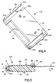
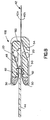
- Figures 3-5 show a second embodiment of a male connector, generally designated 10A, which is substantially identical to connector 10 (Figs. 1 and 2) except that connector 10A includes a resilient strain relief member 33 on the underside of flange 26 as best seen in Figure 5. Consequently, like numerals have been applied in Figures 3-5 designating like components of male connector 10A corresponding to the components described above in relation to connector 10 in Figures 1 and 2.
- flange 26 is a separate rigid plastic component joined to body member 22 by a living hinge 34.
- the living hinge is a molded-in-place component of elastomeric material such as silicone rubber.
- the opposite end of separate flange 26 has a hooked latch 35a for latching over a surface 35b of body member 22. Therefore, the flange can be unlatched to open slot 28 significantly to enable easy positioning of the flexible circuit in the slot.
- Figure 5 clearly shows how resilient component 30 is molded-in-place about a leading edge 22a of body member 22. It also can be seen how flexible circuit 14 is wrapped around leading edge 16 of the connector defined by resilient component 30.
- the invention contemplates that locating holes 18 (Fig. 1) in flexible circuit 14 be spaced such that, when the holes are positioned about locating pegs 20 as seen in Figure 5, the flexible circuit will be wrapped tightly about resilient component 30, even to the extent of slightly compressing the resilient component in the direction of arrow "B". Therefore, the resilient component is effective to spring load the flexible circuit to enhance the engagement thereof with locating pegs 20. In other words, the resilient component is effective to take out any looseness or slack in the flexible circuit which, otherwise, might simply fall off of the locating pegs.
- a first length 14a of the circuit is disposed on top of body member 22, and a second length 14b of the circuit extends beneath flange 26 and away from the rear of the body member. It can be seen that the second length 14b of the circuit is in a plane offset from the plane of the first length 14a of the circuit.
- Resilient strain relief member 33 engages the top of length 14b of the circuit in its plane offset from length 14a of the circuit.
- resilient strain relief member 33 is a molded-in-place structure on the underside of flange 26 and is fabricated of such elastomeric material as silicone rubber.
- connector 10B for interconnecting the conductors 40 on opposite sides of a flat flexible circuit, generally designated 42, to the circuit traces on opposite sides of a printed circuit board 44 as seen in Figures 7 and 8.
- connector 10B includes a multi-part housing, generally designated 46, which is formed by a pair of rigid housing parts 48 and 50.
- Each housing part is a one-piece structure unitarily molded of dielectric material such as rigid plastic.
- the housing parts are movable between open positions shown in Figure 6 to facilitate loading of flexible circuit 42, and closed positions shown in Figures 7 and 8 for interconnecting the conductors of the flexible circuit to the circuit traces of printed circuit board 44.
- the housing parts have complementarily interengaging latch arms 52 which are flexible and molded integrally with the housing parts.
- the latch arms are cantilevered and include complementarily interengaging latch hooks 52a when the housing parts are in their closed positions.
- Housing part 50 has an elongated slot 54 for the passage therethrough of flexible circuit 42 as best seen in Figure 8.
- each housing part includes a resilient spring-loading component 30 at edges thereof about which the flexible circuit is wrapped similar to connectors 10 and 10A.
- the invention contemplates that relatively rigid plastic housing parts 48 and 50 be joined by flexible hinge means provided by a pair of molded-in-place hinge components 56.
- the hinge components are molded of elastomeric material such as silicone rubber. The hinge components accommodate movement of the rigid housing parts from their open positions shown in Figure 6 to their closed positions shown in Figures 7 and 8.
- FIG 8 shows how flexible circuit 42 is interconnected to printed circuit board 44 by connector 10B.
- flexible circuit 42 is a two-sided circuit in that it has conductors on both the top side 42a and the bottom side 42b as viewed in Figure 8.
- printed circuit board 44 will have circuit traces on both sides thereof.
- the flexible circuit is threaded through slot 54 in housing part 50, beneath the housing part and around resilient spring-loading member 30 at the leading edge of the housing part, whereupon bottom side 42b of the flexible circuit becomes the top side for engaging circuit traces on the bottom of printed circuit board 44.
- the circuit is wrapped about a rear edge 60 of housing part 48, over the top of the housing part, around resilient spring-loading component 30 at the front edge of the body part and into engagement with the top of printed circuit board 44.
- the top side 42a of the flexible circuit becomes the bottom side thereof for engaging the circuit traces on the top of the circuit board.
- Both housing parts 48 and 50 are shown in Figure 8 to include locating pegs 20 for insertion into appropriate locating holes in the flexible circuit to tightly wrap the circuit about resilient spring-loading members 30, as described above in relation to connectors 10 and 10A.
- Both housing parts 48 and 50 also include molded-in-place resilient backing structures 62 for biasing the flexible circuit against the top and bottom of the printed circuit board.
Landscapes
- Coupling Device And Connection With Printed Circuit (AREA)
- Multi-Conductor Connections (AREA)
Claims (14)
- Verbinder (10, 10A, 10B) zum elektrischen Verbinden der Leiter (12, 40) einer flachen flexiblen Leitung (14, 42) mit den Leitern einer komplementär zu paarenden Verbindungseinrichtung, der einen Führungsrand aufweist, umfassend:wobei der Verbinder ein nachgiebiges Mittel (30) an dem Rumpfelement (22, 48, 50) umfasst, das an der flexiblen Leitung (14, 42) in Anlage kommen kann;ein Rumpfelement (22, 48, 50), auf welchem die flexible Leitung (14, 42) angeordnet ist, wobei die Leiter (12) der Leitung(14) von dem Rumpfelement abgewandt sind; undPositionierungsmittel (20) an dem Rumpfelement zum Ineingriffbringen und Halten der flexiblen Leitung an diesem;
dadurch gekennzeichnet, dass
die flexible Leitung (14, 42) straff um das nachgiebige Mittel (30) herum geschlagen ist, und zwar in einem Maße, dass das nachgiebige Mittel (30) leicht zusammengedrückt ist, um die flexible Leitung federnd zu beaufschlagen, um den Eingriff derselben mit den Positionierungsmitteln zu verstärken; und dass
sich das nachgiebige Mittel (30) entlang des Führungsrandes (16) des Verbinders (10, 10A, 10B) erstreckt. - Verbinder nach Anspruch 1,
wobei das nachgiebige Mittel eine am Platz angeformte Komponente (30) umfasst. - Verbinder nach Anspruch 2,
wobei das Rumpfelement (22, 48, 50) einheitlich aus Kunststoffmaterial geformt ist und die am Platz angeformte Komponente (30) aus einem elastomeren Material besteht. - Verbinder nach Anspruch 2 oder 3,
wobei die nachgiebige Komponente (30) im Wesentlichen um den Rand (22a) des Rumpfelements (22) herum geformt ist. - Verbinder nach einem der vorhergehenden Ansprüche,
wobei das Rumpfelement (22, 48, 50) aus relativ starrem Kunststoffmaterial geformt ist. - Verbinder nach einem der vorhergehenden Ansprüche,
wobei das nachgiebige Mittel (30) eine Struktur aus Silikongummi darstellt. - Verbinder (10, 10A, 10B) nach einem der vorhergehenden Ansprüche, wobei
der Verbinder ein einzufügender Verbinder (10, 10A) ist; und
das Rumpfelement (22) ein einzufügendes Rumpfelement ist, das einen Rand (22a) aufweist, um welchen herum die flexible Leitung geschlagen ist; und wobei
der einzufügende Verbinder umfasst:Positionierungsmittel (20) an dem Rumpfelement (22) zum Ineingriffbringen und Halten der flexiblen Leitung (14) um den Rand des Rumpfelements herum; undein nachgiebiges Mittel (30) an dem Rumpfelement (22) an dessen Rand (22a), um die flexible Leitung (14) federnd zu beaufschlagen, um den Eingriff derselben mit den Positionierungsmitteln (20) zu verstärken. - Verbinder nach einem der vorhergehenden Ansprüche,
wobei die Positionierungsmittel eine Mehrzahl von Positionierungszapfen (20) umfassen, die von dem Rumpfelement (22) aus in jeweilige Positionierungslöcher (18) in der flexiblen Leitung (14) hineinragen. - Verbinder nach einem der vorhergehenden Ansprüche, welcher zumindest einen der Positionierungszapfen (20) sowie ein jeweiliges Positionierungsloch (18) an jeder der entgegengesetzten Seiten des nachgiebigen Mittels (30) aufweist.
- Verbinder nach einem der vorhergehenden Ansprüche,
wobei das einzufügende Rumpfelement (22) länglich ist und das nachgiebige Mittel einen länglichen, nachgiebigen Streifen (30) entlang des Randes (22a) umfasst. - Verbinder nach einem der vorhergehenden Ansprüche,
wobei die Positionierungsmittel (20) an jeder der entgegengesetzten Seiten des nachgiebigen Streifens (30) angeordnet sind. - Verbinder (10, 10A, 10B) nach einem der vorhergehenden Ansprüche, wobei
der Verbinder ein einzufügender Verbinder (10, 10A) ist; und
das Rumpfelement (22) ein längliches einzufügendes Rumpfelement (22) ist, das einheitlich aus relativ starrem Kunststoffmaterial geformt ist und einen Rand (22a) aufweist, um welchen herum die flexible Leitung (14) geschlagen ist; und wobei
der Verbinder Positionierungsmittel (20) an dem Rumpfelement umfasst, zum Ineingriffbringen und Halten der flexiblen Leitung (14) um den Rand des Rumpfelements herum; sowie
einen länglichen, nachgiebigen Streifen (30), der an seinem Platz entlang des Randes (22a) des Rumpfelements (22) angeformt ist, wobei der Streifen aus elastomerem Material besteht, um die flexible Leitung (14) federnd zu beaufschlagen, um den Eingriff derselben mit den Positionierungsmitteln (20) zu verstärken. - Verbinder nach Anspruch 12,
wobei der nachgiebige Streifen (30) aus Silikongummi hergestellt ist. - Verbinder nach Anspruch 12 oder 13,
welcher zumindest einen der Positionierungszapfen (20) sowie ein jeweiliges Positionierungsloch (18) an jeder der entgegengesetzten Seiten des nachgiebigen Streifens (30) aufweist.
Applications Claiming Priority (2)
| Application Number | Priority Date | Filing Date | Title |
|---|---|---|---|
| US09/064,444 US6086412A (en) | 1998-04-22 | 1998-04-22 | Electrical connector for flat flexible circuitry |
| US64444 | 1998-04-22 |
Publications (3)
| Publication Number | Publication Date |
|---|---|
| EP0952629A2 EP0952629A2 (de) | 1999-10-27 |
| EP0952629A3 EP0952629A3 (de) | 2000-12-27 |
| EP0952629B1 true EP0952629B1 (de) | 2005-12-21 |
Family
ID=22056024
Family Applications (1)
| Application Number | Title | Priority Date | Filing Date |
|---|---|---|---|
| EP99107146A Expired - Lifetime EP0952629B1 (de) | 1998-04-22 | 1999-04-13 | Elektrischer Steckverbinder für flexible Flachband-Schaltkreise |
Country Status (8)
| Country | Link |
|---|---|
| US (1) | US6086412A (de) |
| EP (1) | EP0952629B1 (de) |
| JP (1) | JP3054822B2 (de) |
| KR (1) | KR100360998B1 (de) |
| CN (1) | CN1116711C (de) |
| BR (1) | BR9901385A (de) |
| DE (1) | DE69928983T2 (de) |
| ES (1) | ES2251131T3 (de) |
Families Citing this family (26)
| Publication number | Priority date | Publication date | Assignee | Title |
|---|---|---|---|---|
| DE4329898A1 (de) | 1993-09-04 | 1995-04-06 | Marcus Dr Besson | Kabelloses medizinisches Diagnose- und Überwachungsgerät |
| US6027363A (en) | 1998-04-22 | 2000-02-22 | Molex Incorporated | Electrical connector for flat flexible circuitry |
| US6358064B2 (en) * | 1999-03-29 | 2002-03-19 | Delphi Technologies, Inc. | Z-axis electrical interconnect |
| JP2001068189A (ja) * | 1999-08-27 | 2001-03-16 | Yazaki Corp | コネクタ構造 |
| US6368147B1 (en) * | 2000-03-02 | 2002-04-09 | Microhelix, Inc. | Zero insertion force percutaneous connector and flexible brain probe assembly |
| US6441747B1 (en) | 2000-04-18 | 2002-08-27 | Motorola, Inc. | Wireless system protocol for telemetry monitoring |
| US6496705B1 (en) | 2000-04-18 | 2002-12-17 | Motorola Inc. | Programmable wireless electrode system for medical monitoring |
| AU7596501A (en) | 2000-07-18 | 2002-01-30 | Motorola Inc | Wireless electrocardiograph system and method |
| JP3380539B2 (ja) * | 2000-10-13 | 2003-02-24 | 山一電機株式会社 | フラットケーブル用コネクタ |
| US6688911B2 (en) * | 2000-12-13 | 2004-02-10 | Molex Incorporated | Electrical connector assembly for flat flexible circuitry |
| US6722895B1 (en) * | 2003-01-06 | 2004-04-20 | International Business Machines Corporation | Releasable, repeatable electrical connection employing compression |
| US6540528B2 (en) | 2001-04-26 | 2003-04-01 | International Business Machines Corporation | Releasable, repeatable electrical connections employing compression |
| JP2003022855A (ja) * | 2001-07-09 | 2003-01-24 | Yazaki Corp | ホルダ |
| US7197357B2 (en) | 2001-07-17 | 2007-03-27 | Life Sync Corporation | Wireless ECG system |
| US7933642B2 (en) | 2001-07-17 | 2011-04-26 | Rud Istvan | Wireless ECG system |
| US7378834B2 (en) * | 2002-10-29 | 2008-05-27 | Finisar Corporation | Electronic assembly tester and method for optoelectronic device |
| KR100505650B1 (ko) * | 2002-11-26 | 2005-08-03 | 삼성전자주식회사 | 플렉시블 인쇄회로용 콘넥터 |
| US7503769B2 (en) * | 2006-06-22 | 2009-03-17 | Ddk Ltd. | Connector and pushing jig |
| US8393918B2 (en) * | 2008-06-11 | 2013-03-12 | Pulse Electronics, Inc. | Miniaturized connectors and methods |
| US9039442B2 (en) * | 2011-11-10 | 2015-05-26 | Carmen Rapisarda | Solder-less electrical assembly |
| TWM464866U (zh) * | 2013-07-08 | 2013-11-01 | Yi-Zhi Yang | 連接器 |
| JP6074711B2 (ja) * | 2013-09-10 | 2017-02-08 | パナソニックIpマネジメント株式会社 | ケーブル保持部材、電気的接続装置、コネクタ装置 |
| JP6401676B2 (ja) | 2015-08-06 | 2018-10-10 | モレックス エルエルシー | コネクタ及びコネクタ組立体 |
| JP6597810B2 (ja) * | 2018-02-02 | 2019-10-30 | 日本電気株式会社 | 実装構造、構造部品、実装構造の製造方法 |
| US10637171B1 (en) * | 2019-03-15 | 2020-04-28 | Aptiv Technologies Limited | Electrical connector |
| EP4000138A4 (de) * | 2019-07-16 | 2023-08-23 | CelLink Corporation | Klemmenloser verbinder und schaltungen mit klemmenlosen verbindern |
Family Cites Families (13)
| Publication number | Priority date | Publication date | Assignee | Title |
|---|---|---|---|---|
| US3602870A (en) * | 1969-04-30 | 1971-08-31 | Westinghouse Electric Corp | Connector apparatus for effecting electrical connections |
| IT975428B (it) * | 1972-10-31 | 1974-07-20 | Fiat Spa | Connettore stagno fra cavi e cir cuiti stampati |
| US3825878A (en) * | 1973-09-10 | 1974-07-23 | Motorola Inc | Flexible flat cable system |
| GB2134331B (en) * | 1980-01-17 | 1985-02-06 | Cambion Electronic Products Li | Electrical connectors |
| US4416497A (en) * | 1981-07-27 | 1983-11-22 | Sperry Corporation | Spring clip electrical connector for strip conductor cable |
| US4784615A (en) * | 1987-01-07 | 1988-11-15 | Motorola, Inc. | Direct contact flexible circuit interconnect system and method |
| US4802866A (en) * | 1987-08-10 | 1989-02-07 | Alfiero Balzano | Connector |
| US5009607A (en) * | 1989-07-24 | 1991-04-23 | Rogers Corporation | Flexible circuit connector |
| NL9000087A (nl) * | 1990-01-12 | 1991-08-01 | Du Pont Nederland | Hybride-connector met contactorganen in de vorm van flexibele geleiderfolie. |
| US5297968A (en) * | 1993-01-12 | 1994-03-29 | The Whitaker Corporation | Pluggable connector systems for flexible etched circuits |
| MY131437A (en) * | 1993-01-29 | 2007-08-30 | Minnesota Mining & Mfg | Flexible circuit connector |
| US5383788A (en) * | 1993-05-20 | 1995-01-24 | W. L. Gore & Associates, Inc. | Electrical interconnect assembly |
| US5529502A (en) * | 1994-06-01 | 1996-06-25 | Motorola, Inc. | Solderless flexible circuit carrier to printed circuit board interconnection |
-
1998
- 1998-04-22 US US09/064,444 patent/US6086412A/en not_active Expired - Lifetime
-
1999
- 1999-04-12 JP JP11103676A patent/JP3054822B2/ja not_active Expired - Fee Related
- 1999-04-13 DE DE69928983T patent/DE69928983T2/de not_active Expired - Lifetime
- 1999-04-13 ES ES99107146T patent/ES2251131T3/es not_active Expired - Lifetime
- 1999-04-13 EP EP99107146A patent/EP0952629B1/de not_active Expired - Lifetime
- 1999-04-20 BR BR9901385-1A patent/BR9901385A/pt not_active Application Discontinuation
- 1999-04-21 KR KR1019990014322A patent/KR100360998B1/ko not_active Expired - Fee Related
- 1999-04-21 CN CN99105224A patent/CN1116711C/zh not_active Expired - Fee Related
Also Published As
| Publication number | Publication date |
|---|---|
| DE69928983D1 (de) | 2006-01-26 |
| CN1116711C (zh) | 2003-07-30 |
| CN1233088A (zh) | 1999-10-27 |
| EP0952629A2 (de) | 1999-10-27 |
| DE69928983T2 (de) | 2006-07-20 |
| ES2251131T3 (es) | 2006-04-16 |
| KR100360998B1 (ko) | 2002-11-18 |
| EP0952629A3 (de) | 2000-12-27 |
| JPH11329621A (ja) | 1999-11-30 |
| KR19990083383A (ko) | 1999-11-25 |
| US6086412A (en) | 2000-07-11 |
| BR9901385A (pt) | 2000-01-18 |
| JP3054822B2 (ja) | 2000-06-19 |
Similar Documents
| Publication | Publication Date | Title |
|---|---|---|
| EP0952630B1 (de) | Elektrischer Verbinder für flache flexible Schaltungen | |
| US6086412A (en) | Electrical connector for flat flexible circuitry | |
| EP0963014B1 (de) | Elektrischer Steckverbinderzusammenbau zur Verbindung von flachen flexiblen Schaltungen mit diskreten elektrischen Anschlussklemmen | |
| US6039600A (en) | Male connector for flat flexible circuit | |
| US6162083A (en) | Electrical connector system for flat circuitry | |
| US20080261422A1 (en) | Flat Circuit Connector | |
| US6244890B1 (en) | Male electrical connector for flat flexible circuit | |
| JP2811061B2 (ja) | フラットフレキシブルケーブルをプリント回路板に相互接続するリセプタクルコネクタ | |
| US6015310A (en) | Electrical connector for flat circuitry | |
| US6146171A (en) | Electrical connector for flat circuitry | |
| CN1256789C (zh) | 用于连接扁平柔性电路板与分隔端子的电连接器 | |
| US5584707A (en) | Chip socket system | |
| US6186811B1 (en) | Electrical connector for flat circuitry | |
| US6010357A (en) | System for connecting flat flexible circuitry | |
| EP1439611A1 (de) | Stecker für Bandkabel |
Legal Events
| Date | Code | Title | Description |
|---|---|---|---|
| PUAI | Public reference made under article 153(3) epc to a published international application that has entered the european phase |
Free format text: ORIGINAL CODE: 0009012 |
|
| AK | Designated contracting states |
Kind code of ref document: A2 Designated state(s): DE ES FR IT |
|
| AX | Request for extension of the european patent |
Free format text: AL;LT;LV;MK;RO;SI |
|
| PUAL | Search report despatched |
Free format text: ORIGINAL CODE: 0009013 |
|
| AK | Designated contracting states |
Kind code of ref document: A3 Designated state(s): AT BE CH CY DE DK ES FI FR GB GR IE IT LI LU MC NL PT SE |
|
| AX | Request for extension of the european patent |
Free format text: AL;LT;LV;MK;RO;SI |
|
| 17P | Request for examination filed |
Effective date: 20010616 |
|
| AKX | Designation fees paid |
Free format text: DE ES FR IT |
|
| 17Q | First examination report despatched |
Effective date: 20030922 |
|
| GRAP | Despatch of communication of intention to grant a patent |
Free format text: ORIGINAL CODE: EPIDOSNIGR1 |
|
| GRAS | Grant fee paid |
Free format text: ORIGINAL CODE: EPIDOSNIGR3 |
|
| GRAA | (expected) grant |
Free format text: ORIGINAL CODE: 0009210 |
|
| AK | Designated contracting states |
Kind code of ref document: B1 Designated state(s): DE ES FR IT |
|
| RIC1 | Information provided on ipc code assigned before grant |
Ipc: 7H 01R 12/24 B Ipc: 7H 01R 12/18 A |
|
| REF | Corresponds to: |
Ref document number: 69928983 Country of ref document: DE Date of ref document: 20060126 Kind code of ref document: P |
|
| REG | Reference to a national code |
Ref country code: ES Ref legal event code: FG2A Ref document number: 2251131 Country of ref document: ES Kind code of ref document: T3 |
|
| PGFP | Annual fee paid to national office [announced via postgrant information from national office to epo] |
Ref country code: ES Payment date: 20060426 Year of fee payment: 8 |
|
| ET | Fr: translation filed | ||
| PLBE | No opposition filed within time limit |
Free format text: ORIGINAL CODE: 0009261 |
|
| STAA | Information on the status of an ep patent application or granted ep patent |
Free format text: STATUS: NO OPPOSITION FILED WITHIN TIME LIMIT |
|
| 26N | No opposition filed |
Effective date: 20060922 |
|
| REG | Reference to a national code |
Ref country code: ES Ref legal event code: FD2A Effective date: 20070414 |
|
| PG25 | Lapsed in a contracting state [announced via postgrant information from national office to epo] |
Ref country code: ES Free format text: LAPSE BECAUSE OF NON-PAYMENT OF DUE FEES Effective date: 20070414 |
|
| PGFP | Annual fee paid to national office [announced via postgrant information from national office to epo] |
Ref country code: IT Payment date: 20090428 Year of fee payment: 11 |
|
| PG25 | Lapsed in a contracting state [announced via postgrant information from national office to epo] |
Ref country code: IT Free format text: LAPSE BECAUSE OF NON-PAYMENT OF DUE FEES Effective date: 20100413 |
|
| PGFP | Annual fee paid to national office [announced via postgrant information from national office to epo] |
Ref country code: DE Payment date: 20130429 Year of fee payment: 15 |
|
| PGFP | Annual fee paid to national office [announced via postgrant information from national office to epo] |
Ref country code: FR Payment date: 20130506 Year of fee payment: 15 |
|
| REG | Reference to a national code |
Ref country code: DE Ref legal event code: R119 Ref document number: 69928983 Country of ref document: DE |
|
| REG | Reference to a national code |
Ref country code: FR Ref legal event code: ST Effective date: 20141231 |
|
| REG | Reference to a national code |
Ref country code: DE Ref legal event code: R079 Ref document number: 69928983 Country of ref document: DE Free format text: PREVIOUS MAIN CLASS: H01R0012280000 Ipc: H01R0012500000 |
|
| PG25 | Lapsed in a contracting state [announced via postgrant information from national office to epo] |
Ref country code: DE Free format text: LAPSE BECAUSE OF NON-PAYMENT OF DUE FEES Effective date: 20141101 |
|
| PG25 | Lapsed in a contracting state [announced via postgrant information from national office to epo] |
Ref country code: FR Free format text: LAPSE BECAUSE OF NON-PAYMENT OF DUE FEES Effective date: 20140430 |
|
| REG | Reference to a national code |
Ref country code: DE Ref legal event code: R119 Ref document number: 69928983 Country of ref document: DE Effective date: 20141101 Ref country code: DE Ref legal event code: R079 Ref document number: 69928983 Country of ref document: DE Free format text: PREVIOUS MAIN CLASS: H01R0012280000 Ipc: H01R0012500000 Effective date: 20150127 |