EP0952654A2 - Dispositif de relais de protection pour système de barres conductrices - Google Patents
Dispositif de relais de protection pour système de barres conductrices Download PDFInfo
- Publication number
- EP0952654A2 EP0952654A2 EP99107890A EP99107890A EP0952654A2 EP 0952654 A2 EP0952654 A2 EP 0952654A2 EP 99107890 A EP99107890 A EP 99107890A EP 99107890 A EP99107890 A EP 99107890A EP 0952654 A2 EP0952654 A2 EP 0952654A2
- Authority
- EP
- European Patent Office
- Prior art keywords
- fault
- protective
- absolute value
- unit configured
- idi
- Prior art date
- Legal status (The legal status is an assumption and is not a legal conclusion. Google has not performed a legal analysis and makes no representation as to the accuracy of the status listed.)
- Granted
Links
- 230000001681 protective effect Effects 0.000 title claims description 215
- 230000008859 change Effects 0.000 claims description 39
- 230000005764 inhibitory process Effects 0.000 abstract description 6
- 238000010586 diagram Methods 0.000 description 15
- 238000001514 detection method Methods 0.000 description 11
- 230000035945 sensitivity Effects 0.000 description 11
- 238000012790 confirmation Methods 0.000 description 10
- 230000005540 biological transmission Effects 0.000 description 9
- 238000012545 processing Methods 0.000 description 6
- 101150025634 CTT1 gene Proteins 0.000 description 4
- 230000000694 effects Effects 0.000 description 4
- 230000014509 gene expression Effects 0.000 description 4
- 238000005070 sampling Methods 0.000 description 4
- 230000015572 biosynthetic process Effects 0.000 description 3
- 230000007423 decrease Effects 0.000 description 3
- 238000000034 method Methods 0.000 description 2
- 229920006395 saturated elastomer Polymers 0.000 description 2
- 101100438645 Saccharomyces cerevisiae (strain ATCC 204508 / S288c) CBT1 gene Proteins 0.000 description 1
- 238000013016 damping Methods 0.000 description 1
- 238000013461 design Methods 0.000 description 1
- 238000001914 filtration Methods 0.000 description 1
- 230000004907 flux Effects 0.000 description 1
- 238000009434 installation Methods 0.000 description 1
- 238000005259 measurement Methods 0.000 description 1
- 238000000691 measurement method Methods 0.000 description 1
- 238000012986 modification Methods 0.000 description 1
- 230000004048 modification Effects 0.000 description 1
- 230000002265 prevention Effects 0.000 description 1
- 230000000717 retained effect Effects 0.000 description 1
Images




Classifications
-
- H—ELECTRICITY
- H02—GENERATION; CONVERSION OR DISTRIBUTION OF ELECTRIC POWER
- H02H—EMERGENCY PROTECTIVE CIRCUIT ARRANGEMENTS
- H02H3/00—Emergency protective circuit arrangements for automatic disconnection directly responsive to an undesired change from normal electric working condition with or without subsequent reconnection ; integrated protection
- H02H3/40—Emergency protective circuit arrangements for automatic disconnection directly responsive to an undesired change from normal electric working condition with or without subsequent reconnection ; integrated protection responsive to ratio of voltage and current
-
- H—ELECTRICITY
- H02—GENERATION; CONVERSION OR DISTRIBUTION OF ELECTRIC POWER
- H02H—EMERGENCY PROTECTIVE CIRCUIT ARRANGEMENTS
- H02H7/00—Emergency protective circuit arrangements specially adapted for specific types of electric machines or apparatus or for sectionalised protection of cable or line systems, and effecting automatic switching in the event of an undesired change from normal working conditions
- H02H7/22—Emergency protective circuit arrangements specially adapted for specific types of electric machines or apparatus or for sectionalised protection of cable or line systems, and effecting automatic switching in the event of an undesired change from normal working conditions for distribution gear, e.g. bus-bar systems; for switching devices
-
- H—ELECTRICITY
- H02—GENERATION; CONVERSION OR DISTRIBUTION OF ELECTRIC POWER
- H02H—EMERGENCY PROTECTIVE CIRCUIT ARRANGEMENTS
- H02H7/00—Emergency protective circuit arrangements specially adapted for specific types of electric machines or apparatus or for sectionalised protection of cable or line systems, and effecting automatic switching in the event of an undesired change from normal working conditions
- H02H7/26—Sectionalised protection of cable or line systems, e.g. for disconnecting a section on which a short-circuit, earth fault, or arc discharge has occured
- H02H7/261—Sectionalised protection of cable or line systems, e.g. for disconnecting a section on which a short-circuit, earth fault, or arc discharge has occured involving signal transmission between at least two stations
- H02H7/262—Sectionalised protection of cable or line systems, e.g. for disconnecting a section on which a short-circuit, earth fault, or arc discharge has occured involving signal transmission between at least two stations involving transmissions of switching or blocking orders
Definitions
- This invention relates to a bus-bar protection relay equipment for an electrical power system.
- the protective regions of the bus-bar in electrical power systems are protected by tripping the output based on a combination of outputs described below.
- CT current transformer
- a protective region with a fault is judged in the protective zone based on the above outputs, then the tripping output is sent out to protective regions to separate the protective region with fault from the other protective regions without fault.
- bus-bar protection equipment needs two or more sets of the bus-bar protection relays with CT saturation measurement equipment to protect the bus-bar having a plurality of protective regions.
- a bus-bar protection relay equipment for judging a protective region having a fault, among a protective zone that includes a plurality of protective regions, based on status of a power system, comprises: a first judging unit configured to judge whether an internal fault or an external fault exists in the protective zone by performing a percentage differential protection calculation based on an operating quantity Id and a restrained quantity Ir of the protective zone; a first calculating unit configured to calculate an operating quantity Idi of each protective region, where i is equal to an integer from 1 to n; a second judging unit configured to judge a protective region having the internal fault when an absolute value of a Idi is larger than a coefficient multiplied by an absolute value of a Id; and on output unit configured to output a signal to separate non-fault protective regions from a protective region with the fault based on the result of the first judging unit and the second judging unit.
- a bus-bar protection relay equipment for judging a protective region having a fault, among a protective zone that includes a plurality of protective regions, based on status of a power system comprises: a first judging unit configured to judge whether an internal fault or an external fault exists in the protective zone by performing a percentage differential protection calculation based on an operating quantity Id and a restrained quantity Ir of the protective zone; a first calculating unit configured to calculate an operating quantity Idi of each protective region, where i is equal to an integer from 1 to n; a second judging unit configured to judge a protective region having the internal fault when a difference between an absolute value of the Idi and an absolute value of the Id is smaller than a coefficient multiplied an absolute value of the Id; and an output unit configured to output a signal to separate non-fault protective regions from a protective region with the fault based on the result of the first judging unit and the second judging unit.
- the bus-bar protection relay equipment comprises: wherein the second judging unit configured to judge the protective region having the internal fault when following equations are satisfied: (1) an absolute value of the Idi is more than the coefficient multiplied with an absolute value of the Id, (2) a phase difference between a phase of the Idi and a phase of the Id is more than a designated phase of the Idi to satisfy the equation (1); and an output unit configured to output a signal to separate non-fault protective regions from a protective region with the fault based on the result of the first judging unit and the second judging unit.
- the bus-bar protection relay equipment comprises: wherein the second judging unit configured to judge a protective region having the internal fault when following equations are satisfied: (1) an absolute value of the Idi is a coefficient (less than 1) multiplied with an absolute value of the Id; (2) an absolute value of the Idi is a coefficient (more than 1) multiplied with an absolute value of the Id; (3) a phase difference between a phase of the Idi and a phase of the Id is more than designated phase of the Idi to satisfy the equations (1)and (2); and an output unit configured to output a signal to separate non-fault protective regions from a protective region with the fault based on the result of the first judging unit and the second judging unit.
- the bus-bar protection relay equipment comprises: wherein the second judging unit configured to judge a protective region having the internal fault when following equations are satisfied: an absolute value of the Idi is more than a coefficient (less than 1) multiplied with an absolute value of max ⁇ the Id, prescribed value ⁇ ; and an output unit configured to output a signal to separate non-fault protective regions from a protective region with the fault based on the result of the first judging unit and the second judging unit.
- the bus-bar protection relay equipment comprises: wherein the second judging unit configured to judge a protective region having the internal fault when following equations are satisfied: (1) an absolute value of the Idi is more than a coefficient (less than 1) multiplied with an absolute value of max ⁇ the Id, a prescribed value ⁇ ; (2) a phase difference between a phase of the Idi and a phase of Id is less than a designated phase or the Idi to satisfy the equation (1); and an output unit configured to output a signal to separate non-fault protective regions from a protective region with the fault based on the result of the first judging unit and the second judging unit.
- the bus-bar protection relay equipment comprises: wherein the second judging unit configured to judge a protective region having the internal fault when following equations are satisfied: (1) an absolute value of the Idi is more than a coefficient (less than 1) multiplied with an absolute value of max ⁇ the Id, a prescribed value ⁇ ; (2) an absolute value of the Idi is less than a coefficient multiplied (more than 1) an absolute value of the Id; an output unit configured to output a signal to separate non-fault protective regions from a protective region with the fault based on the result of the first judging unit and the second judging unit.
- the bus-bar protection relay equipment comprises: wherein the second judging unit configured to judge a protective region having the internal fault when following equations are satisfied: (1) an absolute value of the Idi is more than a value which a coefficient (less than 1) multiplied with a sum of an absolute value of the Id and a prescribed value; (2) an absolute value at the Idi is less than a value which a coefficient (more than 1) multiplied with the sum of an absolute value of the Id and a prescribed value; (3) a phase difference between a phase of the Idi and phase of the Id is more than a designated phase among the Idi to satisfy the equations (1)and (2); and an output unit configured to output a signal to separate non-fault protective regions from a protective region with the fault based on the result of the first judging unit and the second judging unit.
- the bus-bar protection relay equipment comprises: wherein the second judging unit configured to judge a protective region having the internal fault when a difference between an absolute value of the Idi and an absolute value of the Id is less than a coefficient multiplied with an absolute value of the Id and that an absolute value of the Idi is more than a coefficient (less than 1) multiplied with a prescribed value; and an output unit configured to output a signal to separate non-fault protective regions from a protective region with the fault based on the result of the first judging unit and the second judging unit.
- the bus-bar protection relay equipment comprises: wherein the second judging unit configured to judge a protective region having the internal fault when following equations are satisfied: (1) an absolute value of the Idi is more than a coefficient (less than 1) multiplied with a prescribed value; (2) an absolute value difference between the Idi and the Id is less than a coefficient multiplied with an absolute value of the Id; and an output unit configured to output a signal to separate non-fault protective regions from a protective region with the fault based on the result of the first judging unit and the second judging unit.
- a bus-bar protection relay equipment for judging a protective region having a fault, among a protective zone that includes two protective regions, based on status of power system, comprising: a first judging unit configured to judge whether an internal fault or an external fault exists in the protective zone by performing a percentage differential protection calculation based on operating quantity and a restrained quantity of the protective zone; a first calculating unit configured to calculate each operating quantity the Idi of two protective regions; a second judging unit configured to judge a protective region having an internal fault when an absolute value of one protective region is larger than a coefficient multiplied with an absolute value of Id and that an absolute value of the other protective region is smaller than a coefficient multiplied with an absolute value of the Id; and an output unit configured to output a signal to separate non-fault protective regions from a protective region with the fault based on the result of the first judging unit and the second judging unit.
- a bus-bar protection relay equipment for judging a protective region having a fault, among a protective zone that includes a plurality of protective regions, based on status of a power system, comprises: a first judging unit configured to judge whether an internal fault or an external fault exists in the protective zone by performing a percentage differential protection calculation based on an operating quantity Id and a restrained quantity Ir of the protective zone; a first calculating unit configured to calculate each operating quantity Idi, where i is equal to an integer from 1 to 2 for two protective regions; a second calculating unit configured to calculate each amount of change ( ⁇ Idi, ⁇ Id) of the Idi and the Id, respectively, in a predetermined time; and a second judging unit configured to judge a protective region having an internal fault when following equations are satisfied: (1) an absolute value of the ⁇ Idi is more than a coefficient multiplied with an absolute value of the ⁇ Id; (2) an absolute value of max ⁇ an absolute value of the ⁇ Id
- a bus-bar protection relay equipment for judging a protective region having a fault, among a protective zone that includes two protective regions, based on status of a power system, comprising: a first judging unit configured to judge whether an internal fault or an external fault exists in the protective zone by performing a percentage differential protection calculation based on an operating quantity Id and a restrained quantity Ir of the protective zone; a first calculating unit configured to calculate each operating quantity Idi, where i is an integrate from 1 to 2 of two protective regions; a second calculating unit configured to calculate each amount of change ⁇ Idi, ⁇ Id for the Idi and the Id, respectively, in a predetermined time; and a second judging unit configured to judge a protective region having an internal fault when an absolute value of the ⁇ Idi is more than a coefficient multiplied with an absolute value of the ⁇ Id.
- a bus-bar protection relay equipment for judging a protective region having a fault, among a protective zone that includes a plurality of protective regions, based on status of a power system, comprises: a first judging unit configured to judge whether an internal fault or an external fault exists in the protective zone by performing a percentage differential protection calculation based on an operating quantity Id and a restrained quantity Ir of the protective zone; a first calculating unit configured to calculate a positive operating quantity Id+ and a negative operating quantity Id- based on an operating quantity Id of a protective zone; a second calculating unit configured to calculate a positive operating quantity Idi+ and a negative operating quantity Idi- based on an operating quantity Idi of each protective region, where i is equal an integer from 1 to n; a second judging unit configured to judge a protective region having an internal fault when following equations are satisfied: (1) an absolute value of the Idi+ is more than a coefficient multiplied with an absolute value of the Id+; (2)
- a bus-bar protection relay equipment for judging a protective region having a fault, among a protective zone that includes a plurality of protective regions, based on status of a power system, comprises: a first judging unit configured to judge whether an internal fault or an external fault exists in the protective zone by performing a percentage differential protection calculation based on an operating quantity Id and a restrained quantity Ir of the protective zone; a first unit configured to calculate amount of change ⁇ Idi of the Idi in a predetermined time; a second unit configured to calculate amount of change ⁇ Id of Id in the predetermined time; a third unit configured to judge a protective region with fault when an absolute value of the ⁇ Idi is more than a coefficient multiplied with an absolute value of the ⁇ Id.
- the bus-bar protection relay equipment comprises wherein the third unit configured to judge a protective region with a fault when followings equations are satisfied: (1) an absolute value of the ⁇ Idi is more than a coefficient multiplied with an absolute value of the ⁇ Id; and (2) an absolute value of max ⁇ the ⁇ Idi ⁇ is more than the coefficient multiplied with the absolute value of the ⁇ Id.
- a bus-bar protection relay equipment for judging a protective region having a fault, among a protective zone that includes a plurality of protective regions, based on status of a power system, comprises: a first judging unit configured to judge whether an internal fault or an external fault exists in the protective zone by performing a percentage differential protection calculation based on an operating quantity Id and a restrained quantity Ir of the protective zone; a first calculating unit configured to calculate an operating quantity Idi of each protective region, where i is equal to an integer from 1 to n; a second judging unit configured to judge a protective region having an internal fault, based on equation between amount of change of the Idi and amount of change of the Id in a predetermined time; a fault detecting unit configured to detect a fault in the power system; and a third judging unit configured send a tripping output exists in the protective region with a fault determined by the second judging unit, the fault detecting unit and the first judging unit.
- the bus-bar protection relay equipment comprises wherein the first judging unit comprising: a first unit configured to calculate amount of the ⁇ Idi of the Idi in a predetermined time; a second unit configured to calculate amount of the ⁇ Id of the Id in the predetermined time; a third unit configured judge a protective region with a fault when an absolute value of the ⁇ Idi is more than a coefficient multiplied with an absolute value of the ⁇ Id.
- the bus-bar protection relay equipment comprises wherein the first judging unit comprising: a first unit configured to calculate amount of a ⁇ Idi of the Idi in a predetermined time; a second unit configured to calculate amount of a ⁇ Id of the Id in a predetermined time; and a third unit configured to judge a protective region with a fault when following equations are satisfied: (1) a phase difference between a phase of the Idi and a phase of the Id is more than a designated phase; and (2) an absolute value of the ⁇ Idi is more than a predetermined value.
- the bus-bar protection relay equipment comprises wherein the first judging unit comprising: a first unit configured to calculate amount of the ⁇ Idi of the Idi in a predetermined time; a second unit configured to calculate amount of the ⁇ Id of the Id in a predetermined time; a third unit configured to judge a protective region with fault when following equations are satisfied: (1) a phase difference between a phase of the Idi and a phase of the Id is more than a designated phase; and (2) an absolute value of the ⁇ Idi is more than an absolute value of the ⁇ Id, and furthermore, comprises wherein the second judging unit comprising: a first unit configured to judge a protective region having a fault, among a protective zone that includes a plurality of protective regions, based on a status of power system, comprising: a first judging unit configured to judge whether an internal fault or an external fault exists in a protective zone by performing a percentage differential protection calculation based on an operating quantity Id and a restrained quantity Ir of the
- Fig.1 is the functional-block diagram related to the 1st, 2nd, 4th and 5th embodiments of a bus-bar protection relay equipment in connection with this invention.
- bus-bar protection relay equipment 10 of an electrical power system includes a data-acquisition means 11, a check zone protection means 12, a fault bus-bar judging means 13, and a tripping bus-bar judging means 14.
- protective region and dependency region have the same meaning.
- the data-acquisition means 11 transforms an analog current signal From a current transformer connected to the bus-bar with two or more dependency regions, into digital data for every predetermined cycle.
- the check zone protection means 12 computes an amount Id (vector sum) of operation, and an amount Ir (scalar sum) of inhibition using the digital data transformed by the data-acquisition means 11.
- the check zone protection means 12 transforms analog current from the current transformer corresponding to each line segment into digital data.
- K0 is a coefficient set in accordance with functions of the protection.
- An actuating signal is outputted when the above equations are not by using the amounts Id and Ir as calculated.
- the internal and external faults in the area which includes the computed value for two or more dependency regions by a predetermined percentage differential protection calculation is judged.
- the fault bus-bar judging means 13 performs a fault bus-bar judging operation for two or more above-mentioned dependency regions using the operating quantity which was computed with the operating quantity and the check zone protection means 12, and outputs a fault bus-bar judging output.
- a tripping bus-bar judging means 14 obtains a tripping bus-bar judging output based on the output of a check zone protection means 12 or an external judging output, and the fault bus-bar judging output from the fault bus-bar judging means 13.
- the isolator conditions (LSA, LSB) of each line are incorporated.
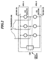
- Discernment of the dependency region by isolator conditions is based on a well-known method. For example, if only LSA has closed conditions when one line is connected with two bus-bars BA and BB by LSA and LSB (Fig.2), current which flows in the concerned line will be introduced into the operation of area A.
- Fig.2 is an example of a system diagram of the bus-bar with two or more dependency regions.
- the bus-bar dependency region of this transmission line 18 is composed of area A on the side of a bus-bar BA, and the area B on the side of a bus-bar BB. These bus-bars BA and the bus-bar BB are divided through the circuit-breaker CBO.
- the bus-bar BA connected to this transmission line 18 and the bus-bar BB are changed by isolators LSA and LSB.
- the amount Id of operation generated in the area which includes two areas turns into the amount (differential current) IdA of operation generated in two dependency regions internal to a bus-bar in the dependency region which the fault generated, and the same quantity.
- a fault bus-bar judging means 13 compares each of the two amounts IdA or IdB of operation computed for every dependency region by each to the amount Id of operation computed with the check zone protection means 12.
- K1 of the above-mentioned equation (4) is a coefficient which is less than or equal to one.
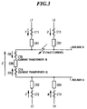
- Fig.3 shows the fault current which flows to the bus-bar for two dependency regions about the feature of the amount (differential current) of operation generated at the time of the fault being explained by an example.
- the bus-bar is divided into the bus-bar BA and the bus-bar BB on both sides of the circuit-breaker CB0, and transmission lines L2 and L4 are connected to transmission lines L1 and L3 and the bus-bar BB at the bus-bar BA.
- differential current generated in the area which includes two areas becomes the same quantity as differential current generated in two dependency regions internal to the bus-bar in the dependency region where the fault was generated.
- the Id computed in the check zone protection means 12 is compared with (IdA or IdB) computed individually in a fault bus-bar judging means 13, in accordance with the dependency region.
- the judgment of a fault bus-bar is attained by confirming that a predetermined equation is satisfied among both regions.
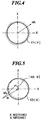
- Fig.4 - Fig.7 show the property principle vector characteristics explaining the equation between the Id computed in a check zone protection means 12 and the operating amount (IdA at the side of a fault bus-bar) computed individually in accordance with each protective area, in the fault bus-bar judging means 13.
- the vertical axis show the impedance(x), and the horizontal axis show the resistance.
- Fig.4 shows the characteristics of the 1st embodiment, compares the absolute value of Id with the absolute value of IdA, and shows the system which distinguishes a fault generating area.
- IdA and Id have as the same quantity theoretically.
- the fault in the area A is judged if equation (13) is satisfied between the absolute value of IdA, and the absolute values of Id by using above-mentioned principle.
- Fig.5 shows characteristics of a 2nd embodiment.
- IdA and Id serve as the same value as in the vector.
- the amount of difference between IdA and Id is equivalent to an error vector, and a big value cannot occur at the time of the fault in area A.
- Fig. 6 shows characteristics of the 3rd embodiment with added phase comparison of Id and IdA to Fig.4.
- phase ( ⁇ ) is also the same for each other.
- Fig.7 shows the conditions which give a maximum, further to the absolute value of IdA, to equation (13) showing the characteristics of the 4th embodiment and showing the equation between the absolute value of Id, and the absolute value of IdA.
- the absolute value of the operating quantity at the time of the fault generation may perform an internal and an external fault judging in an operation means for protection at least, it should become larger than the sensitivity value (KTAP) set up beforehand.
- KTAP sensitivity value
- KTAP is defined as a value to detect a minimum fault current.
- equation (18) are set up as AND conditions with equation (16), the fault bus-bar judging is possible, and also a fault bus-bar judging can also be performed as equation (19) combining with equations (17).
- equation (20) is also effective.
- a sensitivity value (KTAP) multiplied by the predetermined coefficient (K4) as a minimum value of the amount IdA of operation is set up, using equation (21).
- the amount IdA of operation of area A turns into the amount Id of operation of an operation means for protection, and the same quantity as mentioned above when the fault happens in the area A in two dependency regions A and B, the amount IdB of operation of the area B at this time is not generated (it becomes only a part for error).
- the present invention takes into consideration that equation (22) is satisfied between the absolute value of IdB, and the absolute value of Id as conditions of detecting that the fault happened in area A.
- equation (22) is used.
- Tripping bus-bar judging means 14 judges the bus-bar which should be tripped, based on the internal and the external fault judging output from a check zone protection means 12, and the result of judgment of a fault bus-bar judging means 13.
- a check zone protection means 12 performs an internal fault judging and a fault bus-bar judging means outputs the fault judging of area A
- the tripping output to the line connected to the bus-bar of area A is started.
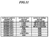
- a tripping bus-bar judging means 14 The judgment of a tripping bus-bar judging means 14 is performed according to Fig.11, and, thereby, tripping starting of a fault generating area (fault bus-bar connection line) is performed.
- Fig. 8 is the functional block diagram related to the 5th, 6th, 7th, and 8th embodiments of the bus-bar protection relay equipment in connection with this invention.
- Bus-bar protection relay equipment 20 of electrical power system includes a data-acquisition means 21, a check zone protection means 22, the amount operation judging means 23, a fault detection means 24, a fault bus-bar judging means 25, a tripping bus-bar judging table 26, and a tripping bus-bar judging means 27.
- the amount operation judging means 23 in operation computes the amount of change ⁇ Idi of operating quantity Idi (i:1 - n) in a predetermined time from the digital data which corresponds for every individual dependency region.
- the amount of change ⁇ Id in the predetermined time of operating quantity Id in the check zone protection means 22 is compared with this amount of change ⁇ Idi of individual dependency region, a fault generating area is judged the individual dependency region where the amount of change ⁇ Idi becomes large among the regions.
- a fault detection means 24 detects faults generated from a changed part in the predetermined time of the digital data transformed by the above-mentioned data-acquisition means 21, or an analog current signal.
- a fault bus-bar judging means 25 outputs the judgment result of the fault bus-bar which extended the judgment result of the above-mentioned amount judging means 23 of operation, and the detection output of the above-mentioned fault detection means 24 at a predetermined time.
- a tripping bus-bar judging table 26 scores the judgment data for tripping bus-bars.
- a tripping bus-bar judging means 27 judges a tripping bus-bar with reference to the judgment table for tripping bus-bars 26 based on the internal or external judging output of the cheek zone protection means 22, and the fault bus-bar judging output of the above-mentioned fault bus-bar judging means 25.
- Fig.2 is the system diagram of the bus-bar with two or more dependency regions.
- This bus-bar dependency region of this transmission line 18 is separated into area A at the side of a bus-bar BA, and area B at the side of a bus-bar BB. These bus-bars BA and the bus-bar BB are divided through the circuit-breaker CBO.
- the bus-bar BA connected to the transmission line 18 and the bus-bar BB serve as the structure which is changed by isolators LSA and LSB.
- a data-acquisition means 21 incorporates current from the current transformer for n lines connected to the bus-bar which has two or more dependency regions for every predetermined cycle, and transforms it into digital data for each line.
- the sequential digital data is sent out to the check zone protection means 22.
- the check zone protection means 22 transforms the analog current from the current transformer of a line segment into digital data for each of the n lines. Regarding the operation processing, more explanation is omitted since the operation of the operating quantity is similar to that of Fig. 1.
- the internal fault judging output of a bus-bar is sent out.
- the amount Id of operation generated in the area which includes the two areas turns into the amount (differential current) IdA of operation generated in two dependency regions internal to the bus-bar in the dependency region which generated the fault, and it is in the same quantity.
- the amount operation judging means 23 compares each of the two amounts IdA or IdB computed for every dependency region by each to the amount Id and computed with an operation means for protection 22.
- Equation (25) When equation (25) is satisfied, it judges with the fault having happened in area A.
- K1 of the above-mentioned equation (25) is a coefficient less than or equal to 1.
- the quantity which applies the predetermined coefficient K1 (K1 is a coefficient less than or equal to 1.) to absolute value
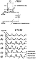
- Fig. 9 and Fig. 10 are figures explaining the effect of the judgment by the above-mentioned equation (26).
- Fig.9 is a system diagram of a standard double bus-bar, and which includes a bus-bar A1, a bus-bar B1, and a circuit-breaker CBT1 that separates the bus-bars A1 and B1.
- Transmission lines LO1 and LO2 are connected to this bus-bar A1 through the circuit-breakers CB11 and CB12.
- CTT1, CT11, and CT12 are current transformers.
- Figs.10(a) to Figs.10(f) are diagrams explaining the amount (current vector sum) of operation computed for CT secondary current at the time of bus-bar B1 fault, and every bus-bar.
- Fig.10 (a) shows secondary current Ip1 of CT11 of Fig.9.
- Fig.10 (b) shows secondary current Ip2 of CT12 of Fig. 9.
- Fig.10 (c) shows secondary current It of CTT1 of Fig. 9.
- the amount IdA of operation in the area of a bus-bar A1 and Fig.10 (f) express the amount IdB of operation in the area of a bus-bar B1, respectively, and the amount Id of operation in the area in which Fig.10 (d) includes both the bus-bars A1 and B1, and Fig.10 (e) assume the case where a current transformer CTT1 results in CT saturation.
- the amount IdA of operation of the bus-bar A1 that should not generate the operating quantity that is a healthy bus-bar increases after saturation start, and the amount IdB of operation of the bus-bar B1 that is a fault bus-bar decreases.
- a fault detection means 24 the absolute value of change part ⁇ I of predetermined time in analog current or the transformed digital data from all the current transformers connected to the bus-bar is added.
- the absolute value of change part ⁇ I is achieved by calculating a differential electrical quantity between present time and fixed time.
- the total of these change part absolute values is compared with the predetermined sensitivity value IK1, and when the total of a change part absolute values is one or more, sensitivity value IK of the following equational expression is predetermined, if the fault has happened for the system, it is detected. ⁇
- IK1 is defined as a value to detect a minimum fault current.
- Judgment operation processing and fault detection processing are performed as mentioned above with the amount operation judging means 23, and a fault detection means 24, and the result is sent out to a fault bus-bar judging means 25.
- the fault bus-bar judging means 25 confirms the judgment result outputted from the amount operation judging means 23, when a fault detected signal is received from a fault detection means 24.
- the area where conditions, such as the above-mentioned a equation (25) and (26), are satisfied is judged to be a fault bus-bar, an abortive area is judged to be a healthy bus-bar, and a predetermined time judging output is retained.
- the tripping output is sent out to a fault generating area based on the internal and the external fault judging output of the check zone protection means 22, and the fault bus-bar judging output of a fault bus-bar judging means 25.
- the check zone protection means 22 outputs an internal fault judging and a fault bus-bar judging means 25 outputs the fault judging of area A
- the judgment data for tripping bus-bars of the table for a tripping bus-bar judging 26 shown in Fig. 11 are referred to.
- the fault judging to the line connected to the bus-bar BA of area A is performed, and tripping output is sent out.
- amount ⁇ Id of change in the predetermined time of the operating quantity obtained from the digital data which is the sampling data with which the amount operation judging means 23 is obtained from the dependency region by each, by amount ⁇ IdA of change and the check zone protection means 22 in the predetermined time of the operating quantity is used.
- the fault bus-bar judging is completed in the predetermined time means the time until it outputs a tripping signal to a fault generating area. Even if it is a fault accompanied by CT saturation, without forming like before two or more relays for the division protection with CT saturation measure, a fault generating area is judged, and a tripping signal can be outputted.
- the 6th embodiment of the bus-bar protection relay equipment in connection with this invention is explained.
- the amount judging means of operation 23A differs from that show in Fig.8, and the other structure follows the explanation of structure shown in Fig.8.
- This protection relay equipment sets two dependency regions as a protection object.
- the amount judging means of operation 23A the amount of change ( ⁇ IdA, ⁇ IdB in the predetermined time of the operating quantity (IdA, IdB) is individually computed to two dependency regions, respectively.
- it judges the area to which the large amount of change ⁇ is obtained with the fault having happened, and outputs to it.
- the amount judging means of operation 23A compares absolute value
- the amount judging means of operation 23A can also judge a fault area only using the condition judging equation (28).
- This bus-bar protection relay equipment sets two dependency regions as a protection object, and performs phase comparison with the amounts IdA and IdB individually computed as the amount judging means of operation 23B to the amount Id and each dependency region which was computed with the check zone protection means 22.
- phase difference When both phase difference are smaller than predetermined phase angle, and, when an amount of change of the operating quantity (for example, ⁇ IdA in area A) in a predetermined time is larger than the predetermined sensitivity value IK2 (sensitivity value which defined IK2 beforehand), for example, (29)
- Fig. 10 is the operating quantity at the time of the fault, the amount Id of the area which includes the amount IdB of the bus-bar B1, and A1 and one B bus-bar which is a fault generating area serves as the same wave in a term until CT become saturated after fault generating.
- the above-mentioned equation (30) may perform a phase comparison judging for confirming the changed level of the required operating quantity.
- the absolute value of the phase difference IdA and IdB is smaller than a predetermined phase angle, for example, 30 degrees.
- Fig. 12 is a functional block diagram showing the ninth embodiment of bus-bar protection relay equipment in connection with this invention.
- This bus-bar protection relay equipment 30 consists of a data-acquisition means 31, a check zone protection means 32, a positive/negative data calculation means 33, a fault bus-bar judging means 34, a tripping bus-bar judging table 35, and a tripping bus-bar judging means 36.
- a positive/negative data calculation means 33 divides the operating quantity of the area which includes two or more dependency regions into positive and negative, and computes it.
- a fault bus-bar judging means 34 measures individually the positive operating quantity, and the negative operating quantity to two or more dependency regions, respectively.
- a fault bus-bar judging means 34 judges the dependency region which the fault has generated, by comparing the operating quantity of the check zone protection means 32 with the positive operating quantity, and the negative operating quantity to two or more dependency regions.
- a tripping bus-bar judging table 35 stores the data for a tripping bus-bar judging shown in Fig. 11.
- the data-acquisition means 31 incorporates the analog current signal from the current transformer connected to the bus-bar which has two or more dependency regions for every predetermined cycle, and transforms and outputs it to digital data.
- the operating quantity and the amount of inhibition are computed using the digital data from the data-acquisition means 31, and the internal and the external fault of the area, which included two or more dependency regions by a predetermined percentage differential protection calculation, are judged and outputted.
- the digital data transformed by the data-acquisition means 31 is decomposed into a right wave and negative wave.
- a predetermined operation for example, the sampling data of 1 cycle (for 360 degrees), is added at the operating quantity of the dependency region which includes two or more dependency regions.
- a fault bus-bar judging means 34 is conventionally well-known, the isolator conditions of each line are incorporated and it discriminates an individual dependency region.
- bus-bar B which is a fault generating bus-bar
- a right wave exists in the amount IdA of operation of bus-bar A which is a healthy bus-bar (refer to Fig. 10(e)).
- the amount, which generates this in connection with CT saturation, of the operating quantity error (error current generated in a healthy bus-bar side) is for generating only in one of a right wave or negative wave.
- This phenomenon is for CT saturation phenomenon mainly occur according to the bias of the magnetic flux in direct current of the current.
- a fault bus-bar can be correctly judged also in the fault accompanied by CT saturation by measuring the absolute value of the positive operating quantity individually computed to two or more dependency regions and the absolute value of the negative operating quantity, and the positive operating quantity and the positive negative operating quantity of an area that includes two or more dependency regions, by right and negative.
- This fault bus-bar judging means 34 is added to the judgment conditions of equations (31) and (32).
- equation (35) and (36) The purpose of equation (35) and (36) is to confirm the level of the required operating quantity to perform the comparison judging by the absolute value of the computed operating quantity.
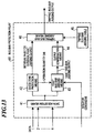
- Fig.13 is a functional-block diagram showing the 10th embodiment of the bus-bar protection relay equipment in connection with this invention.
- This bus-bar protection relay equipment 40 includes a data-acquisition means 41, a check zone protection means 42, a fault bus-bar judging means 43, an output confirmation means 44, and a tripping bus-bar judging table 45.
- a fault bus-bar judging means 43 measures the operating quantity which computes the operating quantity individually of two or more dependency regions, and computes with this operating quantity, and the check zone protection means 42, judges the dependency region where the fault has generated, and sends out a fault bus-bar judging output.
- An output confirmation means 44 confirms whether the same judgment result is continuing during a predetermined time for every dependency region to the output of this fault bus-bar judging means 43.
- the tripping bus-bar judging table 45 stores the tripping bus-bar judging data shown in Fig. 11.
- the check zone protection means 42 If it transforms and outputs to digital data, with the check zone protection means 42, the operating quantity and the amount of inhibition will be computed using the digital data from the data-acquisition means 41.
- the internal and the external faults of the area which included two or bore dependency regions by a predetermined percentage differential protection calculation are judged and outputted.
- the amounts IdA and IdB are individually computed to each dependency region like the fault bus-bar judging means 25 shown in Fig. 8.
- the judgment output of the fault bus-bar judging means 43 is sent out to the output confirmation means 44, and a judgment is made possible also by the fault generated in connection with the CT saturation here.
- the amount of error of the operating quantity accompanied by this CT saturation becomes maximum immediately after generating of the CT saturation, and it decreases after that.
- the damping time constant related to direct current of fault current which is the cause of generating of this CT saturation changes with the impedance of a system, generally, by the fault in a high resistance installation system, even if it is long, it is about 50ms, and the most decreases it between 4 cycles (50Hz system appearance is also 80ms) after the fault.
- a fault bus-bar judging means 43 can confirm whether it is correct or not.
- a tripping bus-bar judging means 46 is supplied.
- the tripping bus-bar judging means 46 sends out a tripping output according to the tripping bus-bar judging table 45 using the internal external fault judging output of the check zone protection means 42, and the output of the confirmation result of the output confirmation means 44.
- a check zone protection means will judge a tripping bus-bar judging means 46, for example, to be an internal fault.
- a fault bus-bar judging means 43 judges with the fault of the area A, the tripping output to the line connected to the bus-bar of the area A is sent out.
- the output confirmation means 44 is formed in the output side of a fault bus-bar judging means 43, and while the judgment output of a fault bus-bar judging means 43 is carrying out time continuation for a predetermined time, the concerned judgment output is sent out.
- a part for the error of the operating quantity accompanied by the CT saturation is not only avoidable, but it can judge the generating area of the fault correctly in the time of the fault accompanied by the CT saturation.
- the effect can be confirmed by filtering the fault bus-bar judging output through the confirmation means 44 before the fault bus-bar judging output is input into the tripping bus-bar judging means.
- bus-bar system was used as into the example, it is not limited to this.
- the design is to judge the fault occurrence area, even when a fault is accompanied by the CT saturation, using the operating quantity obtained from sampling data corresponding to a region that contains multiple protection areas and operating quantities obtained from sampling data corresponding to individual protection areas.
- the discriminating zone protection relays can be reduced. Therefore, cost can be reduced and reliability can be improved with a simplified structure.
Landscapes
- Emergency Protection Circuit Devices (AREA)
Applications Claiming Priority (4)
| Application Number | Priority Date | Filing Date | Title |
|---|---|---|---|
| JP12667898 | 1998-04-21 | ||
| JP12667898A JP3808624B2 (ja) | 1998-04-21 | 1998-04-21 | 系統保護継電装置 |
| JP14291998 | 1998-05-25 | ||
| JP14291998A JP3792893B2 (ja) | 1998-05-25 | 1998-05-25 | 母線保護継電装置 |
Publications (3)
| Publication Number | Publication Date |
|---|---|
| EP0952654A2 true EP0952654A2 (fr) | 1999-10-27 |
| EP0952654A3 EP0952654A3 (fr) | 2000-10-04 |
| EP0952654B1 EP0952654B1 (fr) | 2011-03-09 |
Family
ID=26462825
Family Applications (1)
| Application Number | Title | Priority Date | Filing Date |
|---|---|---|---|
| EP99107890A Expired - Lifetime EP0952654B1 (fr) | 1998-04-21 | 1999-04-21 | Dispositif de relais de protection pour système de barres conductrices |
Country Status (3)
| Country | Link |
|---|---|
| US (1) | US6222711B1 (fr) |
| EP (1) | EP0952654B1 (fr) |
| DE (1) | DE69943254D1 (fr) |
Families Citing this family (9)
| Publication number | Priority date | Publication date | Assignee | Title |
|---|---|---|---|---|
| CN1635679B (zh) * | 2003-12-30 | 2010-12-15 | 许继电气股份有限公司 | Ta饱和时的电流差动保护方法 |
| CN108028529B (zh) * | 2015-09-18 | 2019-12-20 | 施瓦哲工程实验有限公司 | 电力输送系统的时域线路保护 |
| US10180451B2 (en) | 2015-10-13 | 2019-01-15 | Schweitzer Engineering Laboratories, Inc. | Electric power system monitoring using high-frequency signals |
| US10677834B2 (en) | 2018-09-14 | 2020-06-09 | Schweitzer Engineering Laboratories, Inc. | Distance protection of electric power delivery systems using time domain and frequency domain |
| US10641815B2 (en) | 2018-09-27 | 2020-05-05 | Schweitzer Engineering Laboratories, Inc. | Secure distance protection of electric power delivery systems under transient conditions |
| CN110661235B (zh) * | 2019-10-18 | 2021-12-28 | 长园深瑞继保自动化有限公司 | 接入母联开关两侧ct的母线保护方法 |
| KR102792567B1 (ko) * | 2020-01-22 | 2025-04-08 | 한국전력공사 | 실시간 고장 분석 시스템 및 고장 판정 분석 방법 |
| US11735907B2 (en) | 2021-02-03 | 2023-08-22 | Schweitzer Engineering Laboratories, Inc. | Traveling wave overcurrent protection for electric power delivery systems |
| CN114649797B (zh) * | 2022-05-12 | 2025-04-18 | 国网江苏省电力有限公司镇江供电分公司 | 一种消除母联死区的继电保护方法 |
Family Cites Families (6)
| Publication number | Priority date | Publication date | Assignee | Title |
|---|---|---|---|---|
| US3599044A (en) * | 1970-04-30 | 1971-08-10 | Fuji Electric Co Ltd | Superhigh-speed relaying system and apparatus for protection of power systems |
| US4408246A (en) | 1982-01-13 | 1983-10-04 | Westinghouse Electric Corp. | Protective relay apparatus |
| JP2565870B2 (ja) | 1986-06-11 | 1996-12-18 | 株式会社東芝 | 差動継電装置 |
| JP3217353B2 (ja) | 1990-11-21 | 2001-10-09 | 株式会社東芝 | ディジタル形母線保護装置 |
| US5325061A (en) * | 1992-08-27 | 1994-06-28 | Schweitzer Engineering Laboratories, Inc. | Computationally-efficient distance relay for power transmission lines |
| FR2729513B1 (fr) | 1995-01-17 | 1997-04-11 | Schneider Electric Sa | Dispositif de controle-commande d'un systeme electrique |
-
1999
- 1999-04-20 US US09/294,392 patent/US6222711B1/en not_active Expired - Lifetime
- 1999-04-21 DE DE69943254T patent/DE69943254D1/de not_active Expired - Lifetime
- 1999-04-21 EP EP99107890A patent/EP0952654B1/fr not_active Expired - Lifetime
Non-Patent Citations (1)
| Title |
|---|
| None |
Also Published As
| Publication number | Publication date |
|---|---|
| EP0952654B1 (fr) | 2011-03-09 |
| US6222711B1 (en) | 2001-04-24 |
| DE69943254D1 (de) | 2011-04-21 |
| EP0952654A3 (fr) | 2000-10-04 |
Similar Documents
| Publication | Publication Date | Title |
|---|---|---|
| EP1273083B1 (fr) | Relais de protection differentiel destine aux bus electriques a immunite amelioree a la saturation de transformateurs de courant | |
| EP1020729B1 (fr) | Détection de défauts sur lignes électriques | |
| US9425609B2 (en) | Method and apparatus for differential protection of an electric connection | |
| EP0035365B1 (fr) | Procédé et appareil pour la détection de défauts | |
| US4329727A (en) | Directional power distance relay | |
| AU689859B2 (en) | Methods and apparatus for identifying faulted phases on an electric power transmission line | |
| US20100202092A1 (en) | Differential Protection Method, System And Device | |
| US4560922A (en) | Method for determining the direction of the origin of a disturbance affecting an element of an electrical energy transfer network | |
| EP0952654B1 (fr) | Dispositif de relais de protection pour système de barres conductrices | |
| GB1590665A (en) | Protective relay circuit for interphase faults | |
| JP3808624B2 (ja) | 系統保護継電装置 | |
| US8462474B2 (en) | Reclosing system for power transmission line | |
| JPS5893422A (ja) | 高圧送電線路用保護装置 | |
| US11705722B2 (en) | Method for protecting lines in which a reactor device for reactive power compensation is provided on an electrical line and protection assembly including a reactor device for reactive power compensation | |
| US5566082A (en) | Method of detecting a fault section of busbar | |
| EP2502318B1 (fr) | Relais d'interférence floue et procédé de protection différentielle de courant d'une ligne de transmission | |
| US3732464A (en) | Distance relay system | |
| US4513340A (en) | Power transmission line protective apparatus | |
| CA1256486A (fr) | Relais protecteur de transformateur | |
| US4398255A (en) | Polyphase angle estimator | |
| JP3792893B2 (ja) | 母線保護継電装置 | |
| US4755903A (en) | Distance measuring relay for line faults | |
| JP2001103656A (ja) | 母線保護継電装置 | |
| CN114899795B (zh) | 一种在线自整定的变压器后备保护方法及系统 | |
| JP3560297B2 (ja) | 地絡距離継電装置 |
Legal Events
| Date | Code | Title | Description |
|---|---|---|---|
| PUAI | Public reference made under article 153(3) epc to a published international application that has entered the european phase |
Free format text: ORIGINAL CODE: 0009012 |
|
| 17P | Request for examination filed |
Effective date: 19990421 |
|
| AK | Designated contracting states |
Kind code of ref document: A2 Designated state(s): CH DE FR GB LI SE |
|
| AX | Request for extension of the european patent |
Free format text: AL;LT;LV;MK;RO;SI |
|
| PUAL | Search report despatched |
Free format text: ORIGINAL CODE: 0009013 |
|
| AK | Designated contracting states |
Kind code of ref document: A3 Designated state(s): AT BE CH CY DE DK ES FI FR GB GR IE IT LI LU MC NL PT SE |
|
| AX | Request for extension of the european patent |
Free format text: AL;LT;LV;MK;RO;SI |
|
| AKX | Designation fees paid |
Free format text: CH DE FR GB LI SE |
|
| GRAP | Despatch of communication of intention to grant a patent |
Free format text: ORIGINAL CODE: EPIDOSNIGR1 |
|
| GRAS | Grant fee paid |
Free format text: ORIGINAL CODE: EPIDOSNIGR3 |
|
| GRAA | (expected) grant |
Free format text: ORIGINAL CODE: 0009210 |
|
| RAP1 | Party data changed (applicant data changed or rights of an application transferred) |
Owner name: KABUSHIKI KAISHA TOSHIBA |
|
| AK | Designated contracting states |
Kind code of ref document: B1 Designated state(s): CH DE FR GB LI SE |
|
| REG | Reference to a national code |
Ref country code: GB Ref legal event code: FG4D |
|
| REG | Reference to a national code |
Ref country code: CH Ref legal event code: NV Representative=s name: E. BLUM & CO. AG PATENT- UND MARKENANWAELTE VSP Ref country code: CH Ref legal event code: EP |
|
| REF | Corresponds to: |
Ref document number: 69943254 Country of ref document: DE Date of ref document: 20110421 Kind code of ref document: P |
|
| REG | Reference to a national code |
Ref country code: DE Ref legal event code: R096 Ref document number: 69943254 Country of ref document: DE Effective date: 20110421 |
|
| REG | Reference to a national code |
Ref country code: SE Ref legal event code: TRGR |
|
| PLBE | No opposition filed within time limit |
Free format text: ORIGINAL CODE: 0009261 |
|
| STAA | Information on the status of an ep patent application or granted ep patent |
Free format text: STATUS: NO OPPOSITION FILED WITHIN TIME LIMIT |
|
| 26N | No opposition filed |
Effective date: 20111212 |
|
| REG | Reference to a national code |
Ref country code: DE Ref legal event code: R097 Ref document number: 69943254 Country of ref document: DE Effective date: 20111212 |
|
| PGFP | Annual fee paid to national office [announced via postgrant information from national office to epo] |
Ref country code: GB Payment date: 20140416 Year of fee payment: 16 |
|
| PGFP | Annual fee paid to national office [announced via postgrant information from national office to epo] |
Ref country code: SE Payment date: 20140411 Year of fee payment: 16 Ref country code: CH Payment date: 20140414 Year of fee payment: 16 Ref country code: FR Payment date: 20140409 Year of fee payment: 16 Ref country code: DE Payment date: 20140430 Year of fee payment: 16 |
|
| REG | Reference to a national code |
Ref country code: DE Ref legal event code: R119 Ref document number: 69943254 Country of ref document: DE |
|
| REG | Reference to a national code |
Ref country code: CH Ref legal event code: PL |
|
| REG | Reference to a national code |
Ref country code: SE Ref legal event code: EUG |
|
| GBPC | Gb: european patent ceased through non-payment of renewal fee |
Effective date: 20150421 |
|
| PG25 | Lapsed in a contracting state [announced via postgrant information from national office to epo] |
Ref country code: GB Free format text: LAPSE BECAUSE OF NON-PAYMENT OF DUE FEES Effective date: 20150421 Ref country code: CH Free format text: LAPSE BECAUSE OF NON-PAYMENT OF DUE FEES Effective date: 20150430 Ref country code: LI Free format text: LAPSE BECAUSE OF NON-PAYMENT OF DUE FEES Effective date: 20150430 Ref country code: DE Free format text: LAPSE BECAUSE OF NON-PAYMENT OF DUE FEES Effective date: 20151103 |
|
| REG | Reference to a national code |
Ref country code: FR Ref legal event code: ST Effective date: 20151231 |
|
| PG25 | Lapsed in a contracting state [announced via postgrant information from national office to epo] |
Ref country code: FR Free format text: LAPSE BECAUSE OF NON-PAYMENT OF DUE FEES Effective date: 20150430 Ref country code: SE Free format text: LAPSE BECAUSE OF NON-PAYMENT OF DUE FEES Effective date: 20150422 |