EP0952660A2 - Elektromotor - Google Patents
Elektromotor Download PDFInfo
- Publication number
- EP0952660A2 EP0952660A2 EP99303043A EP99303043A EP0952660A2 EP 0952660 A2 EP0952660 A2 EP 0952660A2 EP 99303043 A EP99303043 A EP 99303043A EP 99303043 A EP99303043 A EP 99303043A EP 0952660 A2 EP0952660 A2 EP 0952660A2
- Authority
- EP
- European Patent Office
- Prior art keywords
- magnet
- magnetic poles
- coil
- rotor
- poles
- Prior art date
- Legal status (The legal status is an assumption and is not a legal conclusion. Google has not performed a legal analysis and makes no representation as to the accuracy of the status listed.)
- Granted
Links
Images




Classifications
-
- H—ELECTRICITY
- H02—GENERATION; CONVERSION OR DISTRIBUTION OF ELECTRIC POWER
- H02K—DYNAMO-ELECTRIC MACHINES
- H02K37/00—Motors with rotor rotating step by step and without interrupter or commutator driven by the rotor, e.g. stepping motors
- H02K37/10—Motors with rotor rotating step by step and without interrupter or commutator driven by the rotor, e.g. stepping motors of permanent magnet type
-
- H—ELECTRICITY
- H02—GENERATION; CONVERSION OR DISTRIBUTION OF ELECTRIC POWER
- H02K—DYNAMO-ELECTRIC MACHINES
- H02K21/00—Synchronous motors having permanent magnets; Synchronous generators having permanent magnets
- H02K21/02—Details
-
- H—ELECTRICITY
- H02—GENERATION; CONVERSION OR DISTRIBUTION OF ELECTRIC POWER
- H02K—DYNAMO-ELECTRIC MACHINES
- H02K21/00—Synchronous motors having permanent magnets; Synchronous generators having permanent magnets
- H02K21/12—Synchronous motors having permanent magnets; Synchronous generators having permanent magnets with stationary armatures and rotating magnets
- H02K21/125—Synchronous motors having permanent magnets; Synchronous generators having permanent magnets with stationary armatures and rotating magnets having an annular armature coil
-
- H—ELECTRICITY
- H02—GENERATION; CONVERSION OR DISTRIBUTION OF ELECTRIC POWER
- H02K—DYNAMO-ELECTRIC MACHINES
- H02K2201/00—Specific aspects not provided for in the other groups of this subclass relating to the magnetic circuits
- H02K2201/12—Transversal flux machines
Definitions
- This invention relates to a motor constructed super-compactly.
- a motor formed as a compact motor there is, for example, a compact cylindrically shaped step motor as shown in Fig. 24 of the accompanying drawings.
- this motor is provided with two stators 102 arranged axially of the motor, and each of the stators 102 has two stator yokes 106 disposed so as to be axially opposed to each other.
- a stator coil 105 is concentrically wound on a bobbin 101 held by the two stator yokes 106.
- Each bobbin 101 having the stator coil 105 wound thereon is axially sandwiched and fixed by and between the two stator yokes 106.
- Each of the stator yokes 106, 106 is formed with stator teeth 106a and 106b alternately disposed circumferentially of the inner diametral surface of the bobbin 101.
- the pair of stator yokes 106 and 106 having the stator teeth 106a and 106b are fixed to the case 103 of each stator 102.
- the stators 102 are constructed.
- a flange 115 and a bearing 108 are fixed to one (the left one as viewed in Fig. 24) of the two sets of case 103, and a bearing 108 on the opposite side is fixed to the other (the right one as viewed in Fig. 24) case 103.
- a rotor 109 is of such structure that a rotor magnet 111 is fixed to a rotor shaft 110. An air gap is formed between the outer peripheral surface of the rotor magnet 111 and the inner diametral surface of the stator yoke 106 of the stator 102.
- the rotor shaft 110 is rotatably supported by the two bearings 108 fixed to each case 103.
- Fig. 26 of the accompanying drawings is a plan view exemplifying a step motor driven by a coil which is used in a timepiece or the like.
- the reference numeral 201 designates a rotor comprising a permanent magnet
- the reference numerals 202 and 203 denote stators
- the reference numeral 204 designates a coil.
- This proposed motor is designed such that a rotor comprising a permanent magnet circumferentially equidistantly divided and alternately magnetized to different poles is formed into a cylindrical shape, a first coil, the rotor and a second coil are disposed axially of the rotor in the named order, a first outer magnetic pole and a first inner magnetic pole excited by the first coil are opposed to the outer peripheral surface and inner peripheral surface, respectively, of the rotor, and a second outer magnetic pole and a second inner magnetic pole excited by the second coil are opposed to the outer peripheral surface and inner peripheral surface, respectively, of the rotor, and a rotary shaft which is a rotor shaft is taken out of the cylindrically shaped permanent magnet.
- the motor of such a construction is high in output and can have its outside dimension made small, but the working of its magnetic pole teeth is difficult because the diametral dimension of its inner magnetic poles is small, and it has been desired that a stable output free of fluctuation be obtained from a motor of a small diametral dimension.
- the present invention has been made in view of the above-noted circumstances and an object thereof is to provide a motor which is high in output and is constructed more super-compactly.
- Another object of the present invention is to stabilize the positioning of a rotor when a motor is made into a one-phase motor.
- Fig. 1 is an exploded perspective view of a motor according to Embodiment 1 of the present invention.
- Fig. 2 is a cross-sectional view of the motor shown in Fig. 1 during the assembly thereof.
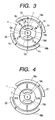
- Fig. 3 shows the positional relation between the rotor and stator of the motor shown in Fig. 2, and shows the state of the rotor when a coil is not electrically energized.
- Fig. 4 shows the state of the rotor when the coil is electrically energized from the state of Fig. 3.
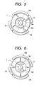
- Fig. 5 shows the state of the rotor when the electrical energization of the coil has been cut off in the state of Fig. 4.
- Fig. 6 shows the state of the rotor when the electrical energization of the coil has been reversed in the state of Fig. 5.
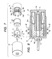
- Fig. 7 is an exploded perspective view of a motor according to Embodiment 2 of the present invention.
- Fig. 8 is a cross-sectional view of the motor shown in Fig. 7 during the assembly thereof.
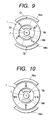
- Fig. 9 shows the positional relation between the rotor and stator of the motor shown in Fig. 8, and shows the state of the rotor when a coil is not electrically energized.
- Fig. 10 shows the state of the rotor when the coil has been electrically energized from the state of Fig. 9.
- Fig. 11 shows the state of the rotor when the electrical energization of the coil has been cut off in the state of Fig. 10.
- Fig. 12 shows the state of the rotor when the electrical energization of the coil has been reversed in the state of Fig. 11.
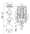
- Fig. 13 is an exploded perspective view of a motor according to Embodiment 3 of the present invention.
- Fig. 14 is a cross-sectional view of the motor shown in Fig. 13 during the assembly thereof.
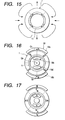
- Fig. 15 is a cross-sectional view showing the state of the magnetic flux of a magnet shown in Fig. 14.
- Fig. 16 shows the positional relation between the rotor and stator of the motor shown in Fig. 14, and shows the state of the rotor when a coil is not electrically energized.
- Fig. 17 shows the intermediate state of the rotor when the coil is electrically energized from the state of Fig. 16.
- Fig. 18 shows the final state of the rotor when the coil is electrically energized from the state of Fig. 16.
- Fig. 19 shows a first intermediate state of the rotor when the electrical energization of the coil has been reversed in the state of Fig. 18.
- Fig. 20 shows a second intermediate state of the rotor when the electrical energization of the coil has been reversed in the state of Fig. 18.
- Fig. 21 shows the final state of the rotor when the electrical energization of the coil has been reversed in the state of Fig. 18.
- Fig. 22 shows the positional relation between the rotor and stator of a motor to which the countermeasure of the present invention is not taken, and shows a first stable state of the rotor when the coil is not electrically energized.
- Fig. 23 shows a second stable state of the rotor when the coil is not electrically energized in Fig. 22.
- Fig. 24 is a cross-sectional view showing a step motor according to the prior art.
- Fig. 25 is an illustration of the magnetic flux of the step motor according to the prior art shown in Fig. 24.
- Fig. 26 is a plan view showing a one-phase motor according to the prior art.
- Fig. 1 is an exploded perspective view of the step motor
- Fig. 2 is a cross-sectional view of the motor shown in Fig. 1 during the assembly thereof.
- the motor according to the present invention is provided with a rotatable rotor magnet 1 circumferentially alternately magnetized to different poles, a cylindrical stator 18 opposed to the rotor magnet 1 with a clearance therebetween, and a coil 2 mounted in the interior of the stator 18, the coil 2 is disposed axially of the rotor magnet 1, the outer magnetic poles 18a and 18b of the stator 18 excited by the coil 2 are opposed to the outer peripheral surface of the magnet 1, the inner magnetic poles 18c and 18d of the stator 18 are opposed to the inner peripheral surface of the magnet 1, and provision is made of holding means for holding the magnet at a location whereat the center of the poles of the magnet deviates from a straight line linking the center of the outer magnetic poles and the center of rotation of the magnet together.
- the present invention will be described with respect to a case where the motor is a step motor.
- the magnet (rotor magnet) 1 constituting a rotor has its outer peripheral surface circumferentially divided into a plurality of portions (in the present embodiment, four portions) and alternately magnetized to S poles and N poles.
- the magnetized portions 1a, 1b, 1c and 1d are magnetized to S poles and the magnetized portions 1b and 1d are magnetized to N poles.
- the centers of the poles of the magnetized portions 1a, 1b, 1c and 1d are shown as K 1 , K 2 , K 3 and K 4 in Fig. 3.
- the magnet 1 is made of a plastic magnet material formed by injection molding. By the magnet 1 being thus made of a plastic magnet material, the thickness thereof with respect to the radial direction of the cylindrical shape of the rotor magnet 1 can be made very small.
- the central portion of the rotor magnet 1 is formed with an axial through-hole, and a fitting portion le having its inner diameter made small is formed on the axially intermediate portion of this through-hole.
- An output shaft 7 which is a rotor shaft is forced into the fitting portion le of the rotor magnet 1 and is secured to the magnet 1.
- the magnet 1 comprises a plastic magnet molded by injection molding and therefore, it is not broken even by an assembling method such as forcing the rotor shaft 7 into the fitting portion. Also, even though the magnet 1 is of a complicated shape having the fitting portion le of a small inner diameter in the axially central portion of the through-hole thereof, it can be manufactured easily. Also, the output shaft 7 and the magnet 1 are assembled together and secured by being forced in and therefore, the assembly becomes easy and it becomes possible to manufacture the motor inexpensively.
- the rotor (magnet rotor) 1 is constituted by the output shaft 7 and the magnet 1.
- the material of the magnet 1 use is made of a plastic magnet formed by injection-molding a mixture, for example, of Nd-Fe-B rare earth magnetic powder and a thermoplastic resin binder material such as polyamide.
- a plastic magnet formed by injection-molding a mixture, for example, of Nd-Fe-B rare earth magnetic powder and a thermoplastic resin binder material such as polyamide.
- the bending strength of a compression-molded magnet is of the order of 500 kgf/cm 2
- polyamide resin is used as the binder material
- bending strength of 800 kgf/cm 2 or greater can be obtained and accordingly, such a thin-walled cylindrical shape that cannot be realized by compression molding can be provided.
- it enhances the performance of the motor to make the magnet into a thin-walled cylindrical shape.
- the shape of the magnet can be freely chosen and an effect which cannot be provided by compression molding, that is, integrating the shape for securing the rotor shaft 7, can be realized, and sufficient rotor shaft securing strength can be obtained. Also, the magnet is excellent in strength and therefore, the rotor shaft 7 will not be damaged (broken) even if use is made of a method of forcing in the rotor shaft 7.
- the secured portion of the rotor shaft 7 is integrally molded, whereby the coaxial accuracy of the magnet portion to the rotor shaft portion is improved and it becomes possible to reduce vibration and it also becomes possible to reduce the clearance distance between the magnet 1 and the stator portion, and the sufficient output torque of the motor can be obtained although the magnetic characteristic of a compression-molded magnet is 8 MGOe or greater, whereas the magnetic characteristic of an injection-molded magnet is of the order of 5 to 7 MGOe.
- the injection-molded magnet has a thin resin coating formed on its surface and therefore, as compared with the compression-molded magnet, the creation of rust is greatly decreased and a rust preventing process such as coating can be eliminated. Also, there is not the adherence of magnetic powder which poses a problem in a compression magnet, and there is nor the swelling of the surface which is liable to occur during the rust preventing coating and thus, the quality can be improved.
- the cylindrically shaped coil 2 is disposed concentrically with and axially of the magnet 1.
- the outer diameter of the coil 2 is substantially equal to the outer diameter of the magnet 1.
- the stator 18 is formed of a soft magnetic material, and comprises an outer cylinder portion and an inner cylinder portion.
- the coil 2 is mounted between the outer cylinder portion and inner cylinder portion of the stator 18. By electrically energizing this coil 2, the stator 18 is excited.
- the fore end portion of the outer cylinder portion of the stator 18 forms outer magnetic poles 18a and 18b, and the fore end portion of the inner cylinder portion of the stator 18 forms inner magnetic poles 18c and 18d.
- the inner magnetic pole 18c and the inner magnetic pole 18d are formed with a deviation of 360/0.5 n degrees, i.e., 180 degrees when as in the present embodiment, the number of magnetic poles is four, so that they may be in phase with each other.
- the outer magnetic pole 18a is disposed in opposed relationship with the inner magnetic pole 18c, and the outer magnetic pole 18b is disposed in opposed relationship with the inner magnetic pole 18d.
- the outer magnetic poles 18a and 18b of the stator 18 are formed by cut-away apertures and teeth extending out in a direction parallel to the shaft.
- the outer magnetic poles 18a, 18b and inner magnetic poles 18c, 18d of the stator 18 are provided in opposed relationship with the outer peripheral surface and inner peripheral surface of one end of the rotor magnet 1 and so as to sandwich one end of the rotor magnet 1 therebetween. Also, one end portion 7b of the output shaft 7 is rotatably fitted in the aperture 18e of the stator 18. Accordingly, a magnetic flux created by the coil 2 crosses the magnet 1 which is the rotor between the outer magnetic poles 18a, 18b and the inner magnetic poles 18c, 18d and therefore, effectively acts on the magnet which is the rotor, and enhances the output of the motor.
- the magnet 1 is formed of a plastic magnet material formed by injection molding, whereby the thickness of the cylindrical shape with respect to the radial direction thereof can be made very small. Therefore, the distance between the outer magnetic poles 18a, 18b and inner magnetic poles 18c, 18d of the stator 18 can be made very small, and the magnetic resistance of a magnetic circuit formed by the coil 2 and the first stator can be made small. Thereby, a great deal of magnetic flux can be created by a small electric current and thus, the increased output and lower power consumption of the motor and the downsizing of the coil are achieved.
- the reference numeral 20 designates a cover as a cylindrical member formed of a non-magnetic material, and the outer diametral portion (the portion on which the outer magnetic poles 18a and 18b are formed) of the stator 18 is fitted and adhesively or otherwise fixed to the inner diametral portion 20a of this cover 20.
- the fitting portion 7a of the output shaft 7 is rotatably fitted in the fitting hole 20b of the cover 20, and one end portion 7b of the output shaft 7 is rotatably fitted in the fitting aperture 18e of the stator 18.
- Figs. 3 to 6 are illustrations successively showing the operation of the motor of Fig. 2 by the use of a cross-sectional view taken along the line 3-3 of Fig. 2.
- Q 1 designates the center of the outer magnetic pole 18a of the stator
- Q 2 denotes the center of the outer magnetic pole 18b of the stator
- Q 3 designate the center of rotation of the rotor magnet 1.
- the reference numerals 21 and 22 denote positioning stators formed of a soft magnetic material. These positioning stators 21 and 22 are secured to the inner diametral portion 20a (Fig. 2) of the cover 20.
- the positioning stators 21 and 22 are opposed to the outer peripheral surface of the rotor magnet 1.
- One positioning stator 21, as shown in Fig. 3, is located between the outer magnetic poles 18a and 18b of the stator 18 and near the outer magnetic pole 18a.
- the other positioning stator 22, as shown in Fig. 3, is located between the outer magnetic poles 18a and 18b of the stator 18 and near the outer magnetic pole 18b.
- These positioning stators 21 and 22 are not in contact with the stator 18 and are not opposed to the inner magnetic poles 18c and 18d or are sufficiently spaced apart from the inner magnetic poles 18c and 18d, whereby even if the coil 2 is electrically energized, they are hardly magnetized as compared with the outer magnetic poles 18a and 18b, and accordingly do not contribute to rotatively driving the rotor magnet 1.
- the stopped position of the magnet when the coil 2 is not electrically energized is set to a position shown in Fig. 3. That is, the magnet 1 is set so as to be stopped at a position (a position shown in Fig. 3) in which the centers K 1 , K 2 , K 3 and K 4 of the poles of the magnetized portion of the magnet 1 deviate from a straight line L 1 linking the centers of the outer magnetic poles 18a and 18b of the stator 18 and the center of rotation of the magnet 1 together.
- K 2 the magnet is stopped at a position deviating by an angle ⁇ .
- the positioning stators 21 and 22 are not excited as previously described, but the outer magnetic poles 18a, 18b and the inner magnetic poles 18c, 18d are excited, and the force with which the excited outer magnetic poles 18a, 18b act on the magnetized portion of the magnet 1 is directed in the direction of rotation of the magnet 1 without fail. Therefore, the magnet (rotor magnet) 1 is actuated smoothly.
- Fig. 22 or 23 are typical cross-sectional views showing these two positions at which the magnet 1 is stably stopped.
- the centers K 1 , K 2 , K 3 and K 4 of the poles of the magnetized portion of the magnet 1 are on a straight line linking the centers Q 1 and Q 2 of the outer magnetic poles and the center of rotation Q 3 of the magnet 1 together and therefore, even if the coil 2 is electrically energized, an electromagnetic force does not act in a direction to rotate the magnet 1.
- the actuation of the magnet 1 is possible by the electrical energization of the coil 2, but unless the electrical energization is changed at a certain timing, the magnet 1 cannot be rotated in its stable state. That is, when from the state of Fig. 23, the outer magnetic poles 18a and 18b are excited, for example, into N poles, even if the electrical energization of the coil 2 is changed over to the opposite direction after the magnet 1 is stopped at the same position as that of Fig. 22, and the outer magnetic poles 18a and 18b are excited into S poles, the electromagnetic force does not act in the direction to rotate the magnet 1, as described in connection with Fig. 22.
- the positioning stators 21 and 21 cooperate with the rotor magnet 1 to constitute holding means for holding the magnet 1. Also, the positioning stators 21 and 22 are located between the outer magnetic poles 18a and 18b of the stator 18 and therefore, can be constructed without making the size of the motor larger.
- the coil 2 is electrically energized to thereby excite the outer magnetic poles and 18a, 18b of the stator 18 into N poles and excite the inner magnetic poles 18c, 18d of the stator 18 into S poles, the magnet 1 which is the rotor is rotated in a counter-clockwise direction as viewed in Fig. 3, and assumes a state shown in Fig. 4.
- the position of the magnet 1 is determined substantially by the excited state of the magnetized portion of the magnet 1 and the outer magnetic poles 18a, 18b and inner magnetic poles 18c, 18d of the stator 18 by the coil 2, and the magnet assumes the state shown in Fig. 4.
- the coil 2 is electrically deenergized, a state stabilized by the magnetic force of the magnet 1 (the position of Fig. 5) is brought about.
- the diameter of the motor can be a size enough to oppose the magnetic poles of the stator 18 to the outer peripheral surface of the magnet 1, and the length of the motor can be the length of the magnet 1 plus the length of the coil 2.
- the size of the motor is determined by the diameters and lengths of the magnet 1 and the coil 2, and by making the diameters and lengths of the magnet 1 and the coil 2 very small, the motor can be made super-compact.
- the diameter of the motor is substantially determined by the outer magnetic poles 18a and 18b opposed to the outer peripheral surface of the rotor magnet 1, and the axial length of the motor is determined by the coil 2 and the rotor magnet 1 being arranged (disposed) axially thereof, and the motor can be made very compact.
- a magnetic flux created by the coil 2 crosses the magnet between the outer magnetic poles and the inner magnetic poles and therefore acts effectively.
- the holding means constituted by the rotor magnet 1 and the positioning stators 21 and 22 opposed to the outer peripheral surface of the magnet 1 and therefore, during the non-energization of the coil 2, the magnet 1 can be held at a position whereat the centers of the pole of the magnet 1 deviate from a straight line linking the centers of the outer magnetic poles and the center of rotation Q 3 of the magnet together.
- the motor can be constituted by a very small number of parts such as the rotor magnet 1, the coil 2, the stator 18 and the output shaft 7 and thus, the cost can be reduced.
- the rotor magnet 1 is formed into a hollow cylindrical shape, and the outer magnetic poles 18a, 18b and the inner magnetic poles 18c, 18d are opposed to the outer peripheral surface and inner peripheral surface, respectively, of this rotor magnet 1 formed into the hollow cylindrical shape, whereby an effective output can be obtained as the motor.
- the output shaft (rotor shaft) 7 is secured to the fitting portion le of the central hole of the magnet 1 which is the rotor by press-in.
- the rotor magnet 1 comprises a plastic magnet formed by injection molding, the rotor magnet 1 is not broken even by the assembly by press-in, and also, even a complicated shape in which the fitting portion le of a small inner diameter is provided in the axially central portion can be manufactured easily. Also, the output shaft 7 and the magnet 1 are assembled and secured by press-in and therefore, the assembly is easy and inexpensive manufacture becomes possible.
- the step motor of the construction described above in Embodiment 1 is of a construction best suited for making the motor super-compact. That is, the fact includes that in the basic construction of the step motor, firstly, the rotor magnet 1 is made into a hollow cylindrical shape, that secondly, the outer peripheral surface of the rotor magnet 1 is circumferentially divided into a plurality and alternately magnetized to different poles, that thirdly, the coil 2 is disposed axially of the rotor magnet 1, that fourthly, the outer magnetic poles and inner magnetic poles of the stator 18 excited by the coil 2 are opposed to the outer peripheral surface and inner peripheral surface, respectively, of the rotor magnet 1, that fifthly, the outer magnetic poles 18a and 18b are formed by cut-away apertures and teeth extending out in a direction parallel to the shaft, and that sixthly, provision is made of holding means for holding the rotor magnet 1 at a position whereat the centers of the poles of the rotor magnet 1 deviate from a
- the diameter of this step motor can be the size enough to oppose the magnetic poles of the stator 18 to the diameter of the rotor magnet 1, and the length of this step motor can be the length of the rotor magnet 1 plus the length of the coil 2.
- the size of the step motor is determined by the diameters and lengths of the rotor magnet 1 and the coil 2, and if the diameters and lengths of the rotor magnet 1 and the coil 2 are made very small, the step motor can be made super-compact.
- the problem of the accuracy of the step motor is solved by a simple construction in which the rotor magnet 1 is formed into a hollow cylindrical shape and the outer magnetic poles and inner magnetic poles of the stator 18 are opposed to the outer peripheral surface and inner peripheral surface, respectively, of the rotor magnet 1 formed into the hollow cylindrical shape. If in that case, not only the outer peripheral surface of the rotor magnet 1, but also the inner peripheral surface of the rotor magnet 1 is circumferentially divided into a plurality and magnetized, the output of the motor can be further enhanced.
- the rotor magnet 1 is formed of a plastic magnet material formed by injection molding, as previously described, whereby the thickness thereof with respect to the radial direction of the cylindrical shape can be made very small. Therefore, the distance between the outer magnetic poles 18a, 18b and inner magnetic poles 18c, 18d of the stator 18 can be made very small, and the magnetic resistance of a magnetic circuit formed by the coil 2 and the stator 18 can be made small. Thereby, a great deal of magnetic flux can be created by a small electric current, and it becomes possible to achieve the increased output and lower power consumption of the motor and the downsizing of the coil.
- Embodiment 2 of the present invention will now be described with reference to Figs. 7 to 12, and the same portions of Embodiment 2 as those of Embodiment 1 are given the same reference characters and need not be described specifically.
- Fig. 7 is an exploded perspective view of a motor according to Embodiment 2 of the present invention
- Fig. 8 is a cross-sectional view of the motor shown in Fig. 7 during the assembly thereof
- Figs. 9 to 12 are illustrations sequentially showing the operation of the motor of Figs. 7 and 8 by the use of a cross-sectional view taken along the line 9-9 of Fig. 8.
- This embodiment 2 also shows a case where the motor is a step motor.
- holding means is constructed by further extending the outer magnetic poles 18a and 18b of the stator 18.
- the outer magnetic poles 18a and 18b comprise portions 18a 1 and 18b 1 opposed to the inner magnetic poles 18c and 18d, and extended portions 18a 2 and 18b 2 .
- the rotor magnet 1 as shown in Fig. 7, is made to differ in magnetization phase between a portion E opposed to the portions 18a 1 and 18b 1 of the outer magnetic poles 18a and 18b and a portion D opposed to the extended portions 18a 2 and 18b 2 .
- the portion E of the magnet 1 when the coil 2 is not electrically energized, the portion E of the magnet 1 is held at a position deviating from a straight line linking the centers of the magnetized portions 18a 1 and 18b 1 of the outer magnetic poles 18a and 18b magnetized by the coil 2 and the center of rotation Q 3 of the magnet 1 together.
- the extended portions 18a 2 and 18b 2 are not opposed to the inner magnetic poles 18c and 18d and therefore, are hardly magnetized as compared with the magnetized portions 18a 1 and 18b 1 even if the coil 2 is electrically energized, and do not produce a driving force. Accordingly, the magnetic flux created from the coil 2 by the electrical energization of the coil 2 substantially passes through the magnetized portions 18a 1 , 18b 1 and the inner magnetic poles 18c, 18d and therefore, a force acting on the rotor magnet 1 does not go toward the center of rotation of the rotor magnet. Therefore, the motor can be actuated stably and smoothly.
- the extended portions 18a 2 and 18b 2 are hardly magnetized as compared with the magnetized portions 18a 1 and 18b 1 even if the coil 2 is electrically energized, and hardly affect the driving force created by the electrical energization of the coil 2. Therefore, a sufficient and stable output can be taken out of the motor.
- the holding means for holding the magnet 1 at a position whereat the centers of the poles of the magnet 1 deviate from a straight line linking the centers of the outer magnetic poles 18a and 18b and the center of rotation Q 3 of the magnet 1 together is constituted by the magnet 1 and the extended portions 18a 2 and 18b 2 opposed to the outer peripheral surface of the magnet 1.
- These extended portions 18a 2 and 18b 2 correspond to the aforedescribed positioning stators 21 and 22, and form positioning stators formed integrally with the outer magnetic poles 18a and 18b.
- the motor step motor
- the coil 2 is electrically energized to thereby excite the outer magnetic poles 18a and 18b of the stator 18 into N poles and the inner magnetic poles 18c and 18d of the stator 18 into S poles, the magnet 1 which is the rotor is rotated in a counter-clockwise direction as viewed in Fig. 9 and assumes a state shown in Fig. 10.
- the extended portions 18a 2 and 18b 2 corresponding to the aforedescribed positioning stators 21 and 22 are hardly excited by the coil 2 and therefore, the position of the magnet 1 is determined substantially by the excited states of the magnetized portions of the magnet 1 and the outer magnetic poles 18a, 18b and inner magnetic poles 18c, 18d of the stator 18 by the coil 2 and the magnet assumes a position shown in Fig. 10.
- the electrical energization of the coil 2 is cut off, the state of Fig. 11 which is a state stabilized by the magnetic force of the magnet 1 is brought about.
- Embodiment 2 of Figs. 7 to 12 differs in the above-described points from Embodiment 1 of Figs. 1 to 6.
- the holding means is constituted by the extended portions 18a 2 and 18b 2 formed integrally with the outer magnetic poles of the stator 18 and the magnet 1 and therefore, the number of parts becomes smaller and assembly becomes easy, and cost can also be reduced.
- the diameter of this step motor can be a size enough to oppose the magnetic poles of the stator 18 to the outer peripheral surface of the magnet 1, and the length of the motor can be the length of the magnet 1 plus the length of the coil 2.
- the size of the motor is determined by the diameters and lengths of the magnet 1 and the coil 2, and by making the diameters and lengths of the magnet 1 and the coil 2 very small, the motor can be made super-compact.
- the problem of the accuracy of the step motor can be solved by simple structure in which the magnet 1 is formed into a hollow cylindrical shape and the outer magnetic poles 18a, 18b and inner magnetic poles 18c, 18d of the stator 18 are opposed to the outer peripheral surface and inner peripheral surface, respectively, of the magnet 1 formed into the hollow cylindrical shape. If in that case, not only the outer peripheral surface of the magnet 1, but also the inner peripheral surface of the magnet is circumferentially divided into a plurality and magnetized, the output of the motor can be further enhanced.
- Embodiment 3 of the present invention will now be described with reference to Figs. 13 to 21, and the same portions as those of Embodiment 1 are given the same reference characters and need not be described specifically.
- Fig. 13 is an exploded perspective view of a motor according to Embodiment 3 of the present invention
- Fig. 14 is a cross-sectional view of the motor shown in Fig. 13 during the assembly thereof.
- a cylinder member 11 formed of a soft magnetic material is secured to the inner peripheral surface of the rotor magnet 1
- the coil 2 is disposed axially of the rotor magnet 1
- the outer magnetic poles 18a and 18b of the stator 18 excited by the coil 2 are opposed to the outer peripheral surface of the magnet 1
- the inner magnetic poles 18c and 18d of the stator 18 are opposed to the inner peripheral surface of the cylinder member 11.
- the cylinder member 11 is formed of a soft magnetic material such as electromagnetic soft iron or pure iron. Therefore, it never happens that the magnetic flux of the magnet 1 leaks to the inner diametral portion of the cylinder member 11.
- Fig. 15 shows the state of the magnetic flux of the magnet 1 to which the cylinder member 11 is secured.
- Figs. 16 to 21 are illustrations sequentially showing the operation of the motor of Figs. 13 to 15 by the use of a cross-sectional view taken along the line 4-4 of Fig. 14.
- Q 1 designates the center of the outer magnetic pole 18a of the stator 18
- Q 2 denotes the center of the outer magnetic pole 18b of the stator 18
- Q 3 designates the center of rotation of the rotor magnet 1.
- the cylinder member 11 formed of a soft magnetic material is secured to the inner diametral portion of the rotor magnet 1 and therefore, it never happens that the magnetic flux of the rotor magnet 1 leaks to the inner diametral portion of the cylinder member 11 and the inner magnetic poles 18c and 18d.
- the stopped position of the rotor magnet 1 during the non-energization of the coil 2, as shown in Fig. 16, is a position at which the center of each pole of the magnetized portion deviates from a straight line linking the centers Q 1 and Q 2 of the outer magnetic poles 18a and 18b of the stator 18 and the center of rotation Q 3 of the magnet 1 together.
- the coil 2 is electrically energized, the force with which the excited outer magnetic poles 18a and 18b act on the magnetized portion of the magnet 1 turns to the direction of rotation of the magnet 1 without fail. Therefore, the magnet (rotor magnet) 1 is actuated smoothly.
- the position at which the magnet 1 is stably stopped when the coil 2 is not electrically energized is a position shown in Fig. 22 or a position shown in Fig. 23.
- Figs. 22 and 23 are typical cross-sectional views showing those two positions. Accordingly, if the step motor described with reference to Figs. 13 to 21 is not provided with the cylinder member 11, the position at which the magnet 1 is stably stopped when the coil 2 is not electrically energized is the position shown in Fig. 22 or 23. If the magnet 1 is stably stopped as shown in Fig.
- the centers of the magnetic poles of the magnetized portion are on a straight line linking the center Q 1 of the outer magnetic poles and the center of rotation Q 3 of the magnet 1 together and therefore, even if the coil 2 is electrically energized, an electromagnetic force does not act in a direction to rotate the magnet 1 and therefore, the magnet cannot be actuated.
- the centers of the poles of the magnetized portion are not on the straight line linking the centers of the outer magnetic poles and the center of rotation of the magnet 1 together and therefore, the electrical energization of the coil 2 is changed over at the timing of Fig. 18 to thereby excite the outer magnetic poles 18a and 18b of the stator 18 into S poles and the inner magnetic poles 18c and 18d of the stator 18 into N poles, whereby the rotor magnet 1 receives a rotatively driving force and is rotated.
- the magnet 1 passes the state of Fig. 19 and is further rotated in the counter-clockwise direction, and momentarily passes the stable state in the electrically energized state shown in Fig. 20, and is further rotated by inertia and rotated to a position shown in Fig. 21.
- the centers of the poles of the magnetized portion are not on the straight line linking the centers of the outer magnetic poles and the center of rotation of the magnet 1 together and therefore, the electrical energization of the coil 2 is changed over at the timing of Fig.
- the diameter of the motor is substantially determined by the outer magnetic poles 18a and 18b opposed to the outer peripheral surface of the rotor magnet 1, and the axial length of the motor is determined by axially arranging (disposing) the coil 2 and the rotor magnet 1, and the motor can be made very compact. Also, a magnetic flux created by the coil 2 crosses the magnet between the outer magnetic poles and the inner magnetic poles and therefore, effectively acts.
- the cylinder member 11 prevents a magnetic flux created from the inner diametral portion of the rotor magnet 1 from going round to the inner magnetic poles 18c and 18d, and during the non-energization of the coil 2, it holds the rotor magnet 1 at a position deviating from the straight line linking the centers of the outer magnetic poles and the center of rotation of the magnet together and therefore, during the stoppage of the motor to the first electrical energization of the coil 2, the force with which the magnetic flux created from the coil 2 acts on the magnet does not go toward the center of rotation of the magnet and accordingly, it becomes possible to effect the starting of smooth and stable rotation.
- the motor can be constructed of a very small number of parts such as the rotor magnet 1, the coil 2, the stator 18, the output shaft 7 and the cylinder member 11 and thus, the cost can be made low.
- the rotor magnet 1 is formed into a hollow cylindrical shape, and the outer magnetic poles 18a, 18b and the inner magnetic poles 18c, 18d are opposed to the outer peripheral surface and inner peripheral surface, respectively, of the rotor magnet 1 formed into the hollow cylindrical shape, whereby an effective output can be obtained as a motor.
- the output shaft (rotor shaft 7) is secured to the fitting portion le of the central hole of the magnet 1 which is the rotor by press-in.
- the rotor magnet 1 comprises a plastic magnet formed by injection molding and therefore, the rotor magnet 1 is not broken even by the assembly by press-in, and even a complicated shape in which the fitting portion le of a small inner diameter is provided in the axially central portion can be manufactured easily. Also, the output shaft 7 and the magnet 1 are assembled and secured by press-in and therefore, the assembly is easy and easy manufacture becomes possible.
- the step motor of the construction described above in Embodiment 3 is of a construction best suited for making the motor super-compact. That is, the fact includes that in the basic construction of the step motor, firstly, the rotor magnet 1 is made into a hollow cylindrical shape, that secondly, the outer peripheral surface of the rotor magnet 1 is circumferentially divided into a plurality and alternately magnetized to different poles, that thirdly, the coil 2 is disposed axially of the rotor magnet 1, that fourthly, the outer magnetic poles and inner magnetic poles of the stator 18 excited by the coil 2 are opposed to the outer peripheral surface and inner peripheral surface, respectively, of the rotor magnet 1, that fifthly, the outer magnetic poles 18a and 18b are formed by cut-away apertures and teeth extending in parallelism to the shaft, and that sixthly, the cylinder member 11 formed of a soft magnetic material is secured to the inner diametral portion of the rotor magnet 1.
- the diameter of this step motor can be a size enough to oppose the magnetic poles of the stator 18 to the diameter of the rotor magnet 1, and the length of this step motor can be the length of the rotor magnet 1 plus the length of the coil 2.
- the size of the step motor is determined by the diameters and lengths of the rotor magnet 1 and the coil 2, and if the diameters and lengths of the rotor magnet 1 and the coil 2 are made very small, the step motor can be made super-compact.
- the problem of the accuracy of the step motor is solved by a simple construction in which the rotor magnet is formed into a hollow cylindrical shape and the outer magnetic poles and inner magnetic poles of the stator 18 are opposed to the outer peripheral surface and inner peripheral surface, respectively, of the rotor magnet 1 formed into the hollow cylindrical shape. If in that case, not only the outer peripheral surface of the rotor magnet 1, but also the inner peripheral surface of the rotor magnet 1 is circumferentially divided into a plurality and magnetized, the output of the motor can be further enhanced.
- the magnetic flux of the rotor magnet 1 can be prevented from leaking to the inner diametral portion of the cylinder member 11 and the inner magnetic poles 18c and 18d by the cylinder member 11. Therefore, the stopped position of the magnet 1 when the coil 2 is not electrically energized is set to a position at which the center of each pole of the magnetized portion of the magnet deviates from a straight line linking the centers Q 1 and Q 2 of the outer magnetic poles 18a and 18b of the stator 18 and the center of rotation Q 3 of the magnet 1 together, as shown in Fig. 16.
- the coil 2 When from this position (deviated position), the coil 2 is electrically energized, the force with which the excited outer magnetic poles 18a and 18b act on the magnetized portion of the magnet 1 turns to the direction of rotation of the magnet 1. Therefore, the magnet 1 is actuated smoothly.
- the rotor magnet 1 is formed of a plastic magnet material formed by injection molding, whereby the thickness thereof with respect to the diametral direction of the cylindrical shape can be made very small. Therefore, the distance between the outer magnetic poles 18a, 18b and inner magnetic poles 18c, 18d of the stator 18 can be made very small, and the magnetic resistance of a magnetic circuit formed by the coil 2 and the stator 18 can be made small. Thereby, a great deal of magnetic flux can be created by a small electric current, and it becomes possible to achieve the increased output and lower power consumption of the motor and the downsizing of the coil.
- the mechanical strength of the magnet 1 can be increased by the cylinder member 11 and accordingly, the magnet 1 can be made thinner. If the magnet 1 is made thinner, the gap between the outer magnetic poles and inner magnetic poles of the stator 18 can be made narrow and correspondingly, magnetic resistance can be reduced. Thereby, it becomes possible to drive the magnet by a small electric current.
- the outer peripheral surface of the magnet is circumferentially divided into n, which are alternately magnetized to S poles and N poles
- the inner peripheral surface of the magnet is also circumferentially divided into n, which are alternately magnetized to S poles and N poles so as to differ from the adjacent outer peripheral surface, but only the outer peripheral surface of the magnet may be circumferentially divided into n, which may be alternately magnetized to S poles and N poles.
- the motor is of a construction which is provided with a rotatable rotor magnet circumferentially alternately magnetized to different poles, a cylindrical stator opposed to the rotor magnet with a clearance therebetween, and a coil mounted in the interior of the stator, and in which said coil is disposed axially of said rotor magnet, the outer magnetic poles of said stator excited by said coil are opposed to the outer peripheral surface of said magnet, the inner magnetic poles of said stator are opposed to the inner peripheral surface of said magnet, and provision is made of holding means for holding said magnet at a position whereat the centers of the poles of said magnet deviate from a straight line linking the centers of said outer magnetic poles and the center of rotation of said magnet together, and therefore the diameter of the motor can be of a size enough to oppose the magnetic poles of the stator to the diameter of said rotor magnet, and the length of the motor can be the length of said rotor magnet plus the length of said coil and thus,
- a motor which is provided with a rotatable rotor magnet circumferentially alternately magnetized to different poles, a cylindrical stator opposed to the rotor magnet with a clearance therebetween, and a coil mounted in the interior of the stator, and in which a cylinder member formed of a soft magnetic material is secured to the inner diametral portion of said rotor magnet, said coil is disposed axially of said rotor magnet, the outer magnetic poles of said stator excited by said coil are opposed to the outer peripheral surface of said magnet, and the inner magnetic poles of said stator are opposed to the inner peripheral surface of said cylinder member, and therefore the diameter of the motor can be a size enough to oppose the magnetic poles of said stator to the diameter of said rotor magnet, and the length of the motor can be the length of said rotor magnet plus the length of said coil and therefore, the diameters and lengths of the rotor magnet and the coil can be made very small to thereby make the motor super-comp
Landscapes
- Engineering & Computer Science (AREA)
- Power Engineering (AREA)
- Permanent Field Magnets Of Synchronous Machinery (AREA)
- Permanent Magnet Type Synchronous Machine (AREA)
Applications Claiming Priority (4)
| Application Number | Priority Date | Filing Date | Title |
|---|---|---|---|
| JP12531398A JP3990811B2 (ja) | 1998-04-20 | 1998-04-20 | モータ |
| JP12531498A JP4011727B2 (ja) | 1998-04-20 | 1998-04-20 | モータ |
| JP12531398 | 1998-04-20 | ||
| JP12531498 | 1998-04-20 |
Publications (3)
| Publication Number | Publication Date |
|---|---|
| EP0952660A2 true EP0952660A2 (de) | 1999-10-27 |
| EP0952660A3 EP0952660A3 (de) | 2000-08-16 |
| EP0952660B1 EP0952660B1 (de) | 2006-03-01 |
Family
ID=26461779
Family Applications (1)
| Application Number | Title | Priority Date | Filing Date |
|---|---|---|---|
| EP99303043A Expired - Lifetime EP0952660B1 (de) | 1998-04-20 | 1999-04-20 | Elektromotor |
Country Status (8)
| Country | Link |
|---|---|
| US (1) | US6400055B1 (de) |
| EP (1) | EP0952660B1 (de) |
| KR (1) | KR100364581B1 (de) |
| CN (1) | CN1178368C (de) |
| DE (1) | DE69930061T2 (de) |
| MY (1) | MY118952A (de) |
| SG (1) | SG94323A1 (de) |
| TW (1) | TW459437B (de) |
Cited By (3)
| Publication number | Priority date | Publication date | Assignee | Title |
|---|---|---|---|---|
| EP1006642B1 (de) * | 1998-12-04 | 2006-07-12 | Canon Kabushiki Kaisha | Elektromotor |
| CN105890833A (zh) * | 2015-02-17 | 2016-08-24 | 操纵技术Ip控股公司 | 轴向通量聚焦型小直径低成本转矩传感器 |
| DE10049107B4 (de) * | 2000-07-07 | 2017-03-23 | Delta Electronics, Inc. | Elektromotorkonstruktion |
Families Citing this family (14)
| Publication number | Priority date | Publication date | Assignee | Title |
|---|---|---|---|---|
| TW476180B (en) * | 1999-09-30 | 2002-02-11 | Sanyo Electric Co | Permanent magnet stepping motor |
| DE10135019A1 (de) * | 2001-07-18 | 2003-01-30 | Bosch Gmbh Robert | Permanentmagnetisch erregter Elektromotor |
| US6897579B2 (en) * | 2001-09-28 | 2005-05-24 | Canon Kabushiki Kaisha | Motor |
| KR20030046763A (ko) * | 2001-12-06 | 2003-06-18 | 삼성전기주식회사 | 스태핑 모터 |
| US6979918B2 (en) * | 2002-12-20 | 2005-12-27 | Canon Kabushiki Kaisha | Actuator |
| US6765319B1 (en) | 2003-04-11 | 2004-07-20 | Visteon Global Technologies, Inc. | Plastic molded magnet for a rotor |
| JP4387858B2 (ja) * | 2004-04-14 | 2009-12-24 | キヤノン株式会社 | ステッピングモータ |
| KR100790542B1 (ko) * | 2005-12-29 | 2008-01-02 | 엘지전자 주식회사 | 자기자화모터 및 고정자 구조 |
| JP4068653B2 (ja) * | 2006-05-31 | 2008-03-26 | 山洋電気株式会社 | モータ用回転子 |
| CN101154862B (zh) * | 2007-09-03 | 2010-09-29 | 中国科学院电工研究所 | 一种双机械端口电机的无刷化内转子 |
| JP5355029B2 (ja) * | 2008-10-20 | 2013-11-27 | キヤノン株式会社 | 駆動装置 |
| DE102009042452A1 (de) * | 2009-09-23 | 2011-03-31 | Elektromotorenwerk Grünhain GmbH & Co. KG | Käfigläufer für elektrische Maschinen und Herstellungsverfahren |
| KR101872897B1 (ko) | 2011-04-25 | 2018-06-29 | 엘지이노텍 주식회사 | 토크 센서의 로터 및 이를 포함하는 토크 센서 |
| CN111637270B (zh) * | 2019-03-01 | 2025-10-28 | 纬湃汽车电子(芜湖)有限公司 | 一种电子膨胀阀 |
Family Cites Families (22)
| Publication number | Priority date | Publication date | Assignee | Title |
|---|---|---|---|---|
| US3149256A (en) | 1960-12-20 | 1964-09-15 | Kohlhagen Walter | Self-starting rotors for synchronous reaction motors |
| US3330975A (en) | 1964-10-15 | 1967-07-11 | Vega Prec Lab Inc | Self-starting synchronous motor |
| FR2214990B1 (de) | 1973-01-18 | 1976-05-14 | Lip Horlogerie | |
| US4012652A (en) * | 1973-04-26 | 1977-03-15 | Electrical Remote Control Company, Ltd. | Unidirectional self-starting electrical motors with shaded poles and shaded magnetic shunt |
| US4004168A (en) * | 1974-08-08 | 1977-01-18 | Tri-Tech, Inc. | Electric rotating machine |
| CH619329A5 (de) * | 1977-07-15 | 1980-09-15 | Sodeco Compteurs De Geneve | |
| JPS5831819B2 (ja) * | 1978-03-10 | 1983-07-08 | 株式会社精工舎 | 小型モ−タ |
| US4207483A (en) * | 1978-09-01 | 1980-06-10 | Warner Electric Brake & Clutch Co. | Step motor with circumferential stators on opposite sides of disc-like rotor |
| CH647107A5 (de) * | 1979-05-30 | 1984-12-28 | Landis & Gyr Ag | Synchronmotor. |
| FR2472867A1 (fr) | 1979-12-26 | 1981-07-03 | Jaeger | Moteur electrique a avance pas a pas et ensemble motoreducteur le mettant en oeuvre |
| JPS61128763A (ja) * | 1984-11-27 | 1986-06-16 | Copal Co Ltd | ステツピングモ−タ |
| CH665510A5 (de) * | 1984-12-06 | 1988-05-13 | Landis & Gyr Ag | Einphasen-schrittmotor. |
| EP0196457A1 (de) * | 1985-04-01 | 1986-10-08 | Saia Ag | Einphasenschrittmotor |
| JPS63113476U (de) * | 1987-01-14 | 1988-07-21 | ||
| DE3871674D1 (de) * | 1987-09-11 | 1992-07-09 | Siemens Ag | Magnetanordnung. |
| US4973866A (en) * | 1989-09-26 | 1990-11-27 | North American Philips Corporation | Variable angle stepper motor |
| US5097162A (en) * | 1989-09-26 | 1992-03-17 | North American Philips Corporation | Variable angle stepper motor with spring magnet |
| US5384506A (en) | 1992-05-29 | 1995-01-24 | Canon Kabushiki Kaisha | Stepper motor |
| AU660249B2 (en) * | 1993-07-08 | 1995-06-15 | Mitsubishi Materials Corporation | Stepping motor |
| US5831356A (en) | 1996-04-08 | 1998-11-03 | Canon Kabushiki Kaisha | Compact cylindrical stepping motor and advancing device |
| DE69707829T2 (de) | 1996-12-27 | 2002-04-04 | Canon K.K., Tokio/Tokyo | Kompakter Schrittmotor |
| JP3517545B2 (ja) * | 1997-02-13 | 2004-04-12 | キヤノン株式会社 | モータ |
-
1999
- 1999-04-16 SG SG9901871A patent/SG94323A1/en unknown
- 1999-04-16 US US09/293,063 patent/US6400055B1/en not_active Expired - Fee Related
- 1999-04-19 TW TW088106243A patent/TW459437B/zh not_active IP Right Cessation
- 1999-04-20 DE DE69930061T patent/DE69930061T2/de not_active Expired - Fee Related
- 1999-04-20 KR KR1019990014098A patent/KR100364581B1/ko not_active Expired - Fee Related
- 1999-04-20 CN CNB99105203XA patent/CN1178368C/zh not_active Expired - Fee Related
- 1999-04-20 EP EP99303043A patent/EP0952660B1/de not_active Expired - Lifetime
- 1999-04-20 MY MYPI99001533A patent/MY118952A/en unknown
Cited By (5)
| Publication number | Priority date | Publication date | Assignee | Title |
|---|---|---|---|---|
| EP1006642B1 (de) * | 1998-12-04 | 2006-07-12 | Canon Kabushiki Kaisha | Elektromotor |
| DE10049107B4 (de) * | 2000-07-07 | 2017-03-23 | Delta Electronics, Inc. | Elektromotorkonstruktion |
| CN105890833A (zh) * | 2015-02-17 | 2016-08-24 | 操纵技术Ip控股公司 | 轴向通量聚焦型小直径低成本转矩传感器 |
| EP3059564A1 (de) * | 2015-02-17 | 2016-08-24 | Steering Solutions IP Holding Corporation | Kostengünstiger axialflussfokussierungs-drehmomentsensor mit kleinem durchmesser |
| US9823146B2 (en) | 2015-02-17 | 2017-11-21 | Steering Solutions Ip Holding Corporation | Axial flux focusing small diameter low cost torque sensor |
Also Published As
| Publication number | Publication date |
|---|---|
| CN1178368C (zh) | 2004-12-01 |
| EP0952660A3 (de) | 2000-08-16 |
| TW459437B (en) | 2001-10-11 |
| SG94323A1 (en) | 2003-02-18 |
| DE69930061D1 (de) | 2006-04-27 |
| DE69930061T2 (de) | 2006-11-09 |
| KR19990083351A (ko) | 1999-11-25 |
| EP0952660B1 (de) | 2006-03-01 |
| KR100364581B1 (ko) | 2002-12-16 |
| CN1233103A (zh) | 1999-10-27 |
| MY118952A (en) | 2005-02-28 |
| US6400055B1 (en) | 2002-06-04 |
Similar Documents
| Publication | Publication Date | Title |
|---|---|---|
| US6400055B1 (en) | Motor | |
| CN100472918C (zh) | 电动机 | |
| US6800970B2 (en) | Motor and optical apparatus using the same | |
| US5973425A (en) | Motor | |
| US6844643B2 (en) | Motor device | |
| KR100550140B1 (ko) | 모터 | |
| US6316851B1 (en) | Motor | |
| JP3517606B2 (ja) | モータ | |
| JP4011727B2 (ja) | モータ | |
| US20060055253A1 (en) | Stepping motor | |
| JP3990811B2 (ja) | モータ | |
| JP3517602B2 (ja) | モータ | |
| JPH09152645A (ja) | カメラ用開閉機構の駆動用モータ | |
| JP2000232766A (ja) | モータ | |
| JP2000175428A (ja) | モータ | |
| JP4378047B2 (ja) | モータ | |
| JP2000175430A (ja) | モータ | |
| JP4250312B2 (ja) | 駆動伝達装置 | |
| JP2002010615A (ja) | モータ | |
| JPH11289739A (ja) | モータ | |
| JP2000175429A (ja) | モータ | |
| JPH1127924A (ja) | モータ | |
| JPH0624420B2 (ja) | 回転アクチュエ−タ | |
| JP4006370B2 (ja) | ステッピングモータ | |
| JP2000236654A (ja) | モータ |
Legal Events
| Date | Code | Title | Description |
|---|---|---|---|
| PUAI | Public reference made under article 153(3) epc to a published international application that has entered the european phase |
Free format text: ORIGINAL CODE: 0009012 |
|
| AK | Designated contracting states |
Kind code of ref document: A2 Designated state(s): DE FR GB |
|
| AX | Request for extension of the european patent |
Free format text: AL;LT;LV;MK;RO;SI |
|
| PUAL | Search report despatched |
Free format text: ORIGINAL CODE: 0009013 |
|
| AK | Designated contracting states |
Kind code of ref document: A3 Designated state(s): AT BE CH CY DE DK ES FI FR GB GR IE IT LI LU MC NL PT SE |
|
| AX | Request for extension of the european patent |
Free format text: AL;LT;LV;MK;RO;SI |
|
| RIC1 | Information provided on ipc code assigned before grant |
Free format text: 7H 02K 21/12 A, 7H 02K 37/12 B, 7H 02K 21/02 B |
|
| 17P | Request for examination filed |
Effective date: 20010117 |
|
| AKX | Designation fees paid |
Free format text: DE FR GB |
|
| 17Q | First examination report despatched |
Effective date: 20031230 |
|
| GRAP | Despatch of communication of intention to grant a patent |
Free format text: ORIGINAL CODE: EPIDOSNIGR1 |
|
| GRAS | Grant fee paid |
Free format text: ORIGINAL CODE: EPIDOSNIGR3 |
|
| GRAA | (expected) grant |
Free format text: ORIGINAL CODE: 0009210 |
|
| AK | Designated contracting states |
Kind code of ref document: B1 Designated state(s): DE FR GB |
|
| REG | Reference to a national code |
Ref country code: GB Ref legal event code: FG4D |
|
| REF | Corresponds to: |
Ref document number: 69930061 Country of ref document: DE Date of ref document: 20060427 Kind code of ref document: P |
|
| ET | Fr: translation filed | ||
| PLBE | No opposition filed within time limit |
Free format text: ORIGINAL CODE: 0009261 |
|
| STAA | Information on the status of an ep patent application or granted ep patent |
Free format text: STATUS: NO OPPOSITION FILED WITHIN TIME LIMIT |
|
| 26N | No opposition filed |
Effective date: 20061204 |
|
| PGFP | Annual fee paid to national office [announced via postgrant information from national office to epo] |
Ref country code: FR Payment date: 20090424 Year of fee payment: 11 Ref country code: DE Payment date: 20090430 Year of fee payment: 11 |
|
| PGFP | Annual fee paid to national office [announced via postgrant information from national office to epo] |
Ref country code: GB Payment date: 20090428 Year of fee payment: 11 |
|
| GBPC | Gb: european patent ceased through non-payment of renewal fee |
Effective date: 20100420 |
|
| REG | Reference to a national code |
Ref country code: FR Ref legal event code: ST Effective date: 20101230 |
|
| PG25 | Lapsed in a contracting state [announced via postgrant information from national office to epo] |
Ref country code: DE Free format text: LAPSE BECAUSE OF NON-PAYMENT OF DUE FEES Effective date: 20101103 |
|
| PG25 | Lapsed in a contracting state [announced via postgrant information from national office to epo] |
Ref country code: GB Free format text: LAPSE BECAUSE OF NON-PAYMENT OF DUE FEES Effective date: 20100420 |
|
| PG25 | Lapsed in a contracting state [announced via postgrant information from national office to epo] |
Ref country code: FR Free format text: LAPSE BECAUSE OF NON-PAYMENT OF DUE FEES Effective date: 20100430 |