EP0952906B1 - Technique et dispositif permettant d'approvisionner en panneaux une scie a panneaux - Google Patents
Technique et dispositif permettant d'approvisionner en panneaux une scie a panneaux Download PDFInfo
- Publication number
- EP0952906B1 EP0952906B1 EP98945501A EP98945501A EP0952906B1 EP 0952906 B1 EP0952906 B1 EP 0952906B1 EP 98945501 A EP98945501 A EP 98945501A EP 98945501 A EP98945501 A EP 98945501A EP 0952906 B1 EP0952906 B1 EP 0952906B1
- Authority
- EP
- European Patent Office
- Prior art keywords
- panels
- stack
- saw machine
- rollers
- loading table
- Prior art date
- Legal status (The legal status is an assumption and is not a legal conclusion. Google has not performed a legal analysis and makes no representation as to the accuracy of the status listed.)
- Expired - Lifetime
Links
- 238000000034 method Methods 0.000 title claims abstract description 19
- 238000012546 transfer Methods 0.000 claims abstract description 19
- 238000013519 translation Methods 0.000 claims abstract description 8
- 230000000875 corresponding effect Effects 0.000 description 3
- 238000010586 diagram Methods 0.000 description 3
- 238000003754 machining Methods 0.000 description 3
- 238000005259 measurement Methods 0.000 description 3
- 230000000284 resting effect Effects 0.000 description 3
- 230000014616 translation Effects 0.000 description 2
- 230000004913 activation Effects 0.000 description 1
- 230000015572 biosynthetic process Effects 0.000 description 1
- 238000010276 construction Methods 0.000 description 1
- 230000002596 correlated effect Effects 0.000 description 1
- 238000012986 modification Methods 0.000 description 1
- 230000004048 modification Effects 0.000 description 1
- 238000011017 operating method Methods 0.000 description 1
- 238000003825 pressing Methods 0.000 description 1
- 238000011144 upstream manufacturing Methods 0.000 description 1
Images



Classifications
-
- B—PERFORMING OPERATIONS; TRANSPORTING
- B65—CONVEYING; PACKING; STORING; HANDLING THIN OR FILAMENTARY MATERIAL
- B65H—HANDLING THIN OR FILAMENTARY MATERIAL, e.g. SHEETS, WEBS, CABLES
- B65H3/00—Separating articles from piles
- B65H3/24—Separating articles from piles by pushers engaging the edges of the articles
- B65H3/242—Separating articles from piles by pushers engaging the edges of the articles for separating a part of the pile, i.e. several articles at once
-
- B—PERFORMING OPERATIONS; TRANSPORTING
- B27—WORKING OR PRESERVING WOOD OR SIMILAR MATERIAL; NAILING OR STAPLING MACHINES IN GENERAL
- B27B—SAWS FOR WOOD OR SIMILAR MATERIAL; COMPONENTS OR ACCESSORIES THEREFOR
- B27B31/00—Arrangements for conveying, loading, turning, adjusting, or discharging the log or timber, specially designed for saw mills or sawing machines
-
- B—PERFORMING OPERATIONS; TRANSPORTING
- B27—WORKING OR PRESERVING WOOD OR SIMILAR MATERIAL; NAILING OR STAPLING MACHINES IN GENERAL
- B27B—SAWS FOR WOOD OR SIMILAR MATERIAL; COMPONENTS OR ACCESSORIES THEREFOR
- B27B31/00—Arrangements for conveying, loading, turning, adjusting, or discharging the log or timber, specially designed for saw mills or sawing machines
- B27B31/003—Arrangements for conveying, loading, turning, adjusting, or discharging the log or timber, specially designed for saw mills or sawing machines with rollers
-
- B—PERFORMING OPERATIONS; TRANSPORTING
- B65—CONVEYING; PACKING; STORING; HANDLING THIN OR FILAMENTARY MATERIAL
- B65H—HANDLING THIN OR FILAMENTARY MATERIAL, e.g. SHEETS, WEBS, CABLES
- B65H2301/00—Handling processes for sheets or webs
- B65H2301/40—Type of handling process
- B65H2301/42—Piling, depiling, handling piles
- B65H2301/422—Handling piles, sets or stacks of articles
- B65H2301/4228—Dividing piles
Definitions
- the present invention relates to panel saws in general and, in particular, to a method for feeding panels to a panel saw machine.
- panel saw machines are used to cut large rough-hewn panels to obtain suitably shaped smaller, semifinished or finished panels.
- the panels are stacked on a loading table on the panel saw machine so as to form regular geometrical stacks, in which the number of panels corresponding with a precise cutting pattern is selected according to the number of items of furniture to be produced.
- Such a panel stacking machine is known for example from EP-A-0,106,019.
- the stacks which are gradually formed on the loading table on the machine are obtained from a large stack located at a loading station further upstream and on a feed line which comprises, one after another, the loading station, the loading table and the cutting station of the panel saw machine.
- the rough-hewn panels are essentially fed from the loading station to the loading table on the panel saw machine using two different pick up and transfer techniques.
- the first envisages moving the various panels by means of sliding, transversal to the stack, of the top panel, which is translated resting on the panel immediately beneath it.
- the second technique envisages the pick up and transfer of the panels which reach the top of the stack, using vacuum pick up means.
- the panels are picked up and transferred following a preparatory stage during which the panel to be transferred is first lifted slightly above the stack, using vacuum pick up means applied to one side of the panel.
- the panel is then intercepted by a horizontally mobile mechanical pusher, which pushes it and feeds it along the feed line, the panel resting on the stack until it arrives at an infeed device, preferably of the type with rollers positioned opposite one another.
- the infeed device transfers the panels received and sends them in series over the loading table on the panel saw machine.
- the panels reach the upright of the loading table, they are released by the infeed device and drop, under their own weight, being deposited one on top of another on the loading table, where suitable aligning means tidy the stack as it is formed.
- suitable transfer means transfer the stack to the panel saw machine for machining.
- the individual panels are first picked up from the top of the stack, until they are completely separated from it, then transferred by a mobile carriage, which mounts the pick up means, over the loading table on the panel saw machine, where they are allowed to drop under their own weight.
- a further disadvantage is the fact that, at present, panel saw machines are fed using systems that are structured to function according to one technique or the other, meaning that it is not normally possible to pick up and transfer rigid and thin panels on the same feed line.
- some known systems envisage the use of twin feed devices, structured according to one pick up and transfer technique or the other, alternating in their operation on the feed line, depending on the type of panels to be fed.
- twin feed devices structured according to one pick up and transfer technique or the other, alternating in their operation on the feed line, depending on the type of panels to be fed.
- this solution is not always economically feasible.
- the aim of the present invention is, therefore, to overcome the above-mentioned disadvantages.
- said aim is achieved by a method for feeding panels to a panel saw machine having the combined features according to claim 1.
- the numeral 1 indicates as a whole a feed line for automatically feeding panels 2 to a panel saw machine, not completely illustrated since it does not form part of the subject matter of the present invention.
- the feed line 1 essentially comprises a loading station 3 for the panels 2 and a loading table 4 on the panel saw machine, located one after another and beneath a structure 5 with a horizontal frame 5a.
- the loading station 3 comprises a horizontal platform 9, guided vertically on a structure 5b fixed to the stand P, and motor-driven so that it can move between two end positions, respectively corresponding with a condition in which the platform 9 is fully lowered and a condition in which it is fully raised off the ground.
- the platform 9 is designed to receive a vertical stack 17 of rough-hewn panels 2, one on top of another, and is designed to move the stack 17 upwards, with short strokes alternating with -pauses.
- the stack 17 strokes and pauses are effected on the basis of state switching signals sent by a photocell 51 located, relative to the stack 17, in a suitable position and at a height at which it is periodically intercepted by the top panel 2 on the stack 17.
- the horizontal frame 5a supports the guide for a carriage 6 which is horizontally mobile above the loading station 3 and is equipped with a set of parallel mechanical pushers 7 (see Figure 2).
- the pushers 7 are supported by support arms, labelled 52 as a whole, which are jointed in such a way as to allow vertical raising and lowering of the pushers 7 relative to the platform 9 of the loading station 3.
- the arms 52 comprise a support element 53 and a vertical guide 56 connected by two pairs of parallel, jointed connecting rods 54 arranged so that, together with the support element 53 and vertical guide 56, they form a four-bar linkage assembly.
- the arms 52 also comprise a cross-member 55 which connects two of the connecting rods, the upper pair labelled 54a in Figure 1a.
- a hydraulic piston 58 is connected to the cross-member, its action allowing the configuration of the quadrilateral to be varied.
- a shoe 59, integral with the pushers 7, is mounted in such a way that it can slide in the guide 56.
- a motor-driven screw 60 controlled by an angular resolver (encoder) 61 is attached to the shoe 59 and imparts to the latter controlled sliding movements whose extent can be modulated along the guide 56.
- the hydraulic piston 58, motor-driven screw 60 and encoder 61 together define first actuator means with which the pushers 7 may be first positioned at a height correlated with the photocell 51, then moved towards the platform 9, to delimit on the stack 17 a micrometrically controlled height h of panels 2, to be transferred from the top of the stack 17 to the panel saw machine.
- the loading table 4 on the panel saw machine is supported by four motor-driven screws 10 (again see Figure 2), equipped with angular resolvers 62, or equivalent systems for detecting positions.
- the motor-driven screws 10 which together with, for example, without limiting the devices which may be used, the encoders 62, define second actuator means, are positioned at right angles to the loading table 4, being located at the corners of the table 4 and controlled in such a way that they impart to the loading table 4 intermittent, gradual translational motion, with short strokes whose extent is controlled between two end positions, in which the loading table 4 is respectively fully raised off the ground and fully lowered.
- the translational motion of the loading table 4 is effected when a command is issued to the motor-driven screws 10, due to a signal corresponding to a panel 2 covering the photocell 63 located at the loading table 4 fully raised position.
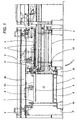
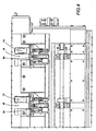
- the feed line 1 comprises an infeed device 8 (see Figures 2 and 3) equipped with a plurality of units 8t arranged in series across the feed line 1.
- Each of the units 8t comprises four horizontal rollers 8s, 8i which form two pairs of vertically overlapping rollers, which are moved along the feed line 1.
- the lower rollers 8i of the infeed device 8 are fixed on the structure 5 and driven, using belt or chain drives 12, by a shared motor 16 (see Figure 4).
- the upper rollers 8s are fitted on the ends of arms 13, attached to the frame 5 of the feed line 1, and are attached to the rods 14 of hydraulic pistons 15 which are the third actuator means of the feed line 1.
- the action of the pistons 15 allows the upper rollers 8s of the infeed device 8 to be raised or lowered on the frame 5, so that they can be moved towards or away from the fixed rollers 8i, pressing any panels 2 between them against the fixed rollers.
- the feed line 1 comprises general control means 70 (see Figure 5), of the programmable type, which are interconnected with the actuator means and the photocells 51, 63 (which identify more general sensor means), so as to automatically control all of the operating sequences of the feed line 1.
- a vertical stack 17 of panels 2 to be cut is placed on the platform 9 in the loading station 3.
- the platform 9, controlled by the feed line 1 control means 70, is translated vertically upwards, in a controlled fashion, until it is in a condition in which at least the top panel 2 of the stack 17 is higher than the pushers 7.
- the upstroke of the stack 17 is stopped.
- the pushers 7 are then lowered so that they are below the photocell 51, alongside the stack 17, until they are lower than the top of the stack 17 by a measurement h determined according to the parameters programmed in the control means 70 depending on the unit thickness of the panels 2 and the number of panels 2 to be transferred from the stack 17 to the panel saw machine.
- the carriage 6 translates along the frame 5a, drawing the pushers 7. The latter, making contact with the stack 17 at the preset height h, transfer the top panel 2, or a set of top panels 2, causing them to translate, transversal to the stack 17, along an initial section of the feed line 1 as far as the infeed device 8.
- the infeed device 8 makes contact with the panel 2 or set of panels 2 received, gripping them between the first pair of rollers 8s, 8i thanks to the thrust exerted by the upper rollers 8s against the opposing action of the fixed lower rollers 8i.
- the infeed device 8 transfers the panel 2 (or set of panels) picked up, sending it along a final section of the feed line 1 until it is above the loading table 4 on the panel saw machine.
- the panel 2 When it reaches the upright of the loading table 4, the panel 2 is released by the infeed device 8 and drops, under its own weight, onto the loading table 4 on the panel saw machine, where it joins the vertical stack of panels 2 previously deposited.
- the feed line 1 control means 70 can control both the vertical translations of the loading station 3 platform 9 and those of the panel saw machine loading table 4, with movements whose extent is controlled, the feed line 1 transfers the various panels 2 taken from the stack 17 in series to the panel saw machine loading table 4, with a control based not on a number of panels preset according to the fixed thickness of a single panel 2, but a control of the total thickness of the panels 2 which may be defined either as the sum of panels with equal unit thickness, or the sum of the thicknesses of panels 2 with varying unit thicknesses, yet which form the total thickness h.
- control means 70 may be programmed to control the translation of the loading table 4, so as to create, on the loading table 4, and depending on the height of the panels 2 (or relative packs of panels 2) passing through the infeed device 8, spaces in which the panels 2 come to rest after a short drop.
- control means may control the separate activation of the hydraulic pistons 15 of the individual pairs of rollers 8s, 8i.
- the feed line 1 according to the present invention can also allow the automatic passage from one series of panels 2 to the other, without necessitating stoppage of the feed line 1, nor the retooling of any physical devices on the line.
- control means 70 can also control series of packs of panels 2 of different thicknesses, which may be combined in any way to obtain an exact total number N of panels to be fed to the panel saw machine.
Landscapes
- Life Sciences & Earth Sciences (AREA)
- Engineering & Computer Science (AREA)
- Mechanical Engineering (AREA)
- Wood Science & Technology (AREA)
- Forests & Forestry (AREA)
- De-Stacking Of Articles (AREA)
- Attitude Control For Articles On Conveyors (AREA)
- Devices For Post-Treatments, Processing, Supply, Discharge, And Other Processes (AREA)
- Sheets, Magazines, And Separation Thereof (AREA)
Claims (7)
- Une technique pour approvisionner en panneaux (2) une scie à panneaux, comprenant une phase de transfert durant laquelle les panneaux (2) d'une pile verticale (17) sont transférés en succession du haut de la pile (17) à une table de chargement (4) de la scie à panneaux, la phase de transfert comprenant une translation des panneaux (2), transversale à la pile (17) le long d'une ligne d'alimentation (1) dont la section initiale est parcourue par les panneaux (2) sous la poussée d'au moins un pousseur (7) mobile à l'horizontale, jusqu'à atteindre un dispositif d'entrée (8) pourvu de rouleaux (8s, 8i) opposés, lesdits panneaux (2), sous l'action du dispositif d'entrée (8) parcourant une section finale de la ligne d'alimentation (1), entre le dispositif d'entrée (8) lui-même et la table de chargement (4) de la scie à panneaux, la technique étant caractérisée en ce que le pousseur (7) et la pile verticale (17) effectuent une translation transversale par rapport à la ligne d'alimentation (1), avec des déplacements dont l'ampleur est commandée par des moyens de contrôle (70), de manière à permettre au pousseur (7) de venir au contact de la pile (17) et de transférer de cette même pile un panneau ou plusieurs panneaux (2) afin de former des paquets de panneaux superposés en fonction de l'ampleur (h) de la translation correspondante.
- La technique selon la revendication 1, caractérisée en ce que les moyens de contrôle (70) peuvent être programmés de manière à gérer le transfert en succession de panneaux (2) correspondant à une épaisseur (h) de la pile (17) jusqu'à former une pile (17') sur la table de chargement (4) de la scie à panneaux, cette dernière pile ayant une hauteur totale (H) et un nombre total (N) prédéfini et quelconque de panneaux, obtenu comme une succession appropriée de hauteurs (h) de panneaux (2) transférés en séquence de la station de chargement (3) à la table de chargement (4) de la scie à panneaux.
- La technique selon la revendication 2, caractérisée en ce que les épaisseurs (h) des panneaux (2) peuvent être différentes.
- La technique selon la revendication 1, caractérisée en ce qu'elle comprend une phase de translation verticale de la table de chargement (4) de la scie à panneaux, l'ampleur de ladite phase de translation étant gérée par des moyens de contrôle (70) en fonction de la hauteur (h) des paquets de la pile (17) passant à travers le dispositif d'entrée (8), la phase de translation étant gérée de manière à ce que la table de chargement (4) de la scie à panneaux soit progressivement déplacée afin de créer, sur la table de chargement (4) elle-même, des espaces correspondants dans lesquels les paquets de panneaux (2) sont déposés avec une hauteur de chute réduite.
- La technique selon la revendication 1, caractérisée en ce que le nombre de panneaux (2) qui composent les paquets est sélectionné via les moyens de contrôle (70) dans une proportion inverse à l'épaisseur unitaire des panneaux (2) présents dans la pile (17).
- Un dispositif d'entrée, comprenant au moins une paire de rouleaux (8s, 8i) horizontaux, parallèles et superposés à la verticale, un premier rouleau (8i) étant fixe et motorisé, le second rouleau (8s) étant monté de manière à pouvoir tourner librement et à se déplacer par translation afin de pouvoir presser un ou plusieurs panneaux (2) positionnés entre les deux rouleaux (8s, 8i) contre l'action opposée du rouleau fixe (8i), ledit dispositif étant caractérisé en ce qu'il comprend au moins deux paires desdits rouleaux (8s, 8i), translatées l'une par rapport à l'autre le long de la ligne d'alimentation (1) des panneaux (2), et en ce que la hauteur des seconds rouleaux (8s) peut être réglée via des moyens de contrôle (70) en fonction de la hauteur (h) des paquets de panneaux (2) passant à travers lesdites paires de rouleaux (8s, 8i) à cet instant.
- Le dispositif d'entrée selon la revendication 6, caractérisé en ce que l'entraxe (D) des seconds rouleaux (8s) desdites paires de rouleaux (8s, 8i) peut être réglé de façon séparée.
Applications Claiming Priority (3)
| Application Number | Priority Date | Filing Date | Title |
|---|---|---|---|
| ITBO970620 | 1997-10-16 | ||
| IT97BO000620A IT1295230B1 (it) | 1997-10-16 | 1997-10-16 | Metodo di alimentazione di pannelli ad una macchina sezionatrice. |
| PCT/IB1998/001609 WO1999020441A1 (fr) | 1997-10-16 | 1998-10-13 | Technique et dispositif permettant d'approvisionner en panneaux une scie a panneaux |
Publications (2)
| Publication Number | Publication Date |
|---|---|
| EP0952906A1 EP0952906A1 (fr) | 1999-11-03 |
| EP0952906B1 true EP0952906B1 (fr) | 2005-03-02 |
Family
ID=11342594
Family Applications (1)
| Application Number | Title | Priority Date | Filing Date |
|---|---|---|---|
| EP98945501A Expired - Lifetime EP0952906B1 (fr) | 1997-10-16 | 1998-10-13 | Technique et dispositif permettant d'approvisionner en panneaux une scie a panneaux |
Country Status (7)
| Country | Link |
|---|---|
| US (1) | US6481954B1 (fr) |
| EP (1) | EP0952906B1 (fr) |
| AT (1) | ATE289901T1 (fr) |
| CA (1) | CA2272682C (fr) |
| DE (1) | DE69829164T2 (fr) |
| IT (1) | IT1295230B1 (fr) |
| WO (1) | WO1999020441A1 (fr) |
Cited By (1)
| Publication number | Priority date | Publication date | Assignee | Title |
|---|---|---|---|---|
| WO2021012202A1 (fr) * | 2019-07-24 | 2021-01-28 | 福建省得力机电有限公司 | Machine intelligente de coupe et de sciage de billes |
Families Citing this family (5)
| Publication number | Priority date | Publication date | Assignee | Title |
|---|---|---|---|---|
| IT1309239B1 (it) * | 1999-05-07 | 2002-01-16 | Selco Spa | Impianto per il prelievo e l'alimentazione di pannelli |
| ITBO20130003A1 (it) * | 2013-01-02 | 2014-07-03 | Valter Naldi | Macchina sezionatrice di pannelli |
| TWI593616B (zh) * | 2014-06-27 | 2017-08-01 | 巴柏斯特麥克斯合資公司 | 用於將板片元件供給至機器的方法,供給平台以及裝備該供給平台的加工機 |
| EP3069838B1 (fr) * | 2015-03-18 | 2021-12-29 | BIESSE S.p.A. | Machine pour usinage de panneaux en bois ou analogue |
| CN108705608B (zh) * | 2018-05-29 | 2023-06-09 | 湖南茂源林业有限责任公司 | 全自动木材切割设备 |
Family Cites Families (11)
| Publication number | Priority date | Publication date | Assignee | Title |
|---|---|---|---|---|
| GB335344A (en) * | 1928-10-04 | 1930-09-25 | Panhard & Levassor | Improvements in machines for the manufacture of oak floor boards |
| US3844426A (en) * | 1970-09-10 | 1974-10-29 | J Campbell | Method for cutting panels |
| US3908836A (en) * | 1974-05-01 | 1975-09-30 | Takashi Ikeda | Apparatus for supplying sheets to a sheet processing machine in successive stacks |
| IT1156610B (it) * | 1982-06-24 | 1987-02-04 | Giben Impianti Spa | Impianto per impilare automaticamente su rispettive tavole elevatrici, pannelli o pacchi di pannelli di dimensione diversa, prodotti da un impianto di sezionatura |
| JPS6246601A (ja) * | 1985-08-26 | 1987-02-28 | 橋本電機工業株式会社 | 細幅長尺単板の連続自動処理装置 |
| DE3901537A1 (de) * | 1989-01-20 | 1990-08-02 | Holzma Maschinenbau Gmbh | Auf einem horizontal verfahrbaren einschubwagen angeordnete platteneinschubvorrichtung |
| DE4100458C2 (de) * | 1991-01-09 | 1996-12-05 | Erwin Jenkner | Plattenzuführvorrichtung für Plattenaufteilsägen |
| AT396891B (de) * | 1991-01-15 | 1993-12-27 | Schelling & Co | Einrichtung zum beschicken von aufteilsägeanlagen |
| AT401261B (de) * | 1992-07-20 | 1996-07-25 | Schelling & Co | Einrichtung zum beschicken von werkzeugmaschinen |
| DE4227478A1 (de) * | 1992-08-20 | 1994-02-24 | Kolbus Gmbh & Co Kg | Vorrichtung zum fortlaufenden Anlegen von Buchblocks |
| FI96298C (fi) * | 1992-11-19 | 1996-06-10 | Sunds Defibrator Panelhandling | Menetelmä levynipun syöttämiseksi levypinosta |
-
1997
- 1997-10-16 IT IT97BO000620A patent/IT1295230B1/it active IP Right Grant
-
1998
- 1998-10-13 US US09/308,450 patent/US6481954B1/en not_active Expired - Fee Related
- 1998-10-13 AT AT98945501T patent/ATE289901T1/de active
- 1998-10-13 WO PCT/IB1998/001609 patent/WO1999020441A1/fr not_active Ceased
- 1998-10-13 EP EP98945501A patent/EP0952906B1/fr not_active Expired - Lifetime
- 1998-10-13 CA CA002272682A patent/CA2272682C/fr not_active Expired - Fee Related
- 1998-10-13 DE DE69829164T patent/DE69829164T2/de not_active Expired - Lifetime
Cited By (1)
| Publication number | Priority date | Publication date | Assignee | Title |
|---|---|---|---|---|
| WO2021012202A1 (fr) * | 2019-07-24 | 2021-01-28 | 福建省得力机电有限公司 | Machine intelligente de coupe et de sciage de billes |
Also Published As
| Publication number | Publication date |
|---|---|
| CA2272682A1 (fr) | 1999-04-29 |
| ITBO970620A0 (it) | 1997-10-16 |
| IT1295230B1 (it) | 1999-05-04 |
| ATE289901T1 (de) | 2005-03-15 |
| DE69829164D1 (de) | 2005-04-07 |
| DE69829164T2 (de) | 2006-04-13 |
| CA2272682C (fr) | 2007-09-18 |
| ITBO970620A1 (it) | 1999-04-16 |
| US6481954B1 (en) | 2002-11-19 |
| EP0952906A1 (fr) | 1999-11-03 |
| WO1999020441A1 (fr) | 1999-04-29 |
Similar Documents
| Publication | Publication Date | Title |
|---|---|---|
| CA2645172C (fr) | Dispositif d'estampage dote d'un systeme d'amenee | |
| KR880000616B1 (ko) | 프레스 또는 유사한 가공물 처리 기계에 있어서의 가공물 반출입 장치 | |
| EP0963270B1 (fr) | Machine a scier des panneaux pourvue d'un pourvoyeur a deplacement lateral et technique afferente | |
| EP0216235B1 (fr) | Machine pour trier, empiler et empaqueter des tuiles céramiques classifiées selon le type | |
| US4976584A (en) | Apparatus for loading cartons onto pallets | |
| US4986726A (en) | Plant for automatically stacking and orderly arranging packs of panels of different sizes | |
| US5700128A (en) | Feeding or stacking device for slab-shaped workpieces | |
| CN109203434A (zh) | 一种全自动纸浆餐具覆膜设备 | |
| US4893982A (en) | Apparatus for conveying workpiece | |
| CN112845936A (zh) | 包装盒自动折弯生产线 | |
| US6481954B1 (en) | Method and device for feeding panels to a panel saw machine | |
| EP0654407B1 (fr) | Machine pour emballer des articles | |
| CN113911451B (zh) | 一种工件打包方法 | |
| US6607069B2 (en) | Crank drive for returning work pieces | |
| EP4188687B1 (fr) | Machine pour envelopper des boîtes déjà mises en forme avec une feuille de recouvrement | |
| CN114104403B (zh) | 一种输送系统 | |
| CN116117535B (zh) | 一种门芯板自动化雕刻线 | |
| CN112875315B (zh) | 一种控制叠合装置自动调整叠合高度的方法 | |
| CN214191614U (zh) | 一种高速凸轮包面纸机 | |
| CN208933626U (zh) | 一种多层布料定位输送装置 | |
| CN221316962U (zh) | 一种随动的快速折纸装置 | |
| US5695596A (en) | Apparatus for laying up veneer panels | |
| CN222906858U (zh) | 一种送料设备及自动裁剪系统 | |
| CN116081031B (zh) | 一种纸皮位置伺服调整与输送的紧凑型设备 | |
| CN212449943U (zh) | 一种铝基板码放装置 |
Legal Events
| Date | Code | Title | Description |
|---|---|---|---|
| PUAI | Public reference made under article 153(3) epc to a published international application that has entered the european phase |
Free format text: ORIGINAL CODE: 0009012 |
|
| AK | Designated contracting states |
Kind code of ref document: A1 Designated state(s): AT DE ES FI IT SE |
|
| 17P | Request for examination filed |
Effective date: 19990615 |
|
| RAP1 | Party data changed (applicant data changed or rights of an application transferred) |
Owner name: GIBEN INTERNATIONAL S.P.A. |
|
| GRAP | Despatch of communication of intention to grant a patent |
Free format text: ORIGINAL CODE: EPIDOSNIGR1 |
|
| GRAS | Grant fee paid |
Free format text: ORIGINAL CODE: EPIDOSNIGR3 |
|
| GRAA | (expected) grant |
Free format text: ORIGINAL CODE: 0009210 |
|
| AK | Designated contracting states |
Kind code of ref document: B1 Designated state(s): AT DE ES FI IT SE |
|
| PG25 | Lapsed in a contracting state [announced via postgrant information from national office to epo] |
Ref country code: FI Free format text: LAPSE BECAUSE OF FAILURE TO SUBMIT A TRANSLATION OF THE DESCRIPTION OR TO PAY THE FEE WITHIN THE PRESCRIBED TIME-LIMIT Effective date: 20050302 Ref country code: ES Free format text: LAPSE BECAUSE OF FAILURE TO SUBMIT A TRANSLATION OF THE DESCRIPTION OR TO PAY THE FEE WITHIN THE PRESCRIBED TIME-LIMIT Effective date: 20050302 |
|
| REF | Corresponds to: |
Ref document number: 69829164 Country of ref document: DE Date of ref document: 20050407 Kind code of ref document: P |
|
| PLBE | No opposition filed within time limit |
Free format text: ORIGINAL CODE: 0009261 |
|
| STAA | Information on the status of an ep patent application or granted ep patent |
Free format text: STATUS: NO OPPOSITION FILED WITHIN TIME LIMIT |
|
| 26N | No opposition filed |
Effective date: 20051205 |
|
| PG25 | Lapsed in a contracting state [announced via postgrant information from national office to epo] |
Ref country code: SE Free format text: LAPSE BECAUSE OF FAILURE TO SUBMIT A TRANSLATION OF THE DESCRIPTION OR TO PAY THE FEE WITHIN THE PRESCRIBED TIME-LIMIT Effective date: 20050602 |
|
| PGFP | Annual fee paid to national office [announced via postgrant information from national office to epo] |
Ref country code: AT Payment date: 20101028 Year of fee payment: 13 |
|
| PGFP | Annual fee paid to national office [announced via postgrant information from national office to epo] |
Ref country code: IT Payment date: 20101026 Year of fee payment: 13 |
|
| PGFP | Annual fee paid to national office [announced via postgrant information from national office to epo] |
Ref country code: DE Payment date: 20101227 Year of fee payment: 13 |
|
| PG25 | Lapsed in a contracting state [announced via postgrant information from national office to epo] |
Ref country code: DE Free format text: LAPSE BECAUSE OF NON-PAYMENT OF DUE FEES Effective date: 20120501 |
|
| REG | Reference to a national code |
Ref country code: DE Ref legal event code: R119 Ref document number: 69829164 Country of ref document: DE Effective date: 20120501 |
|
| PG25 | Lapsed in a contracting state [announced via postgrant information from national office to epo] |
Ref country code: IT Free format text: LAPSE BECAUSE OF NON-PAYMENT OF DUE FEES Effective date: 20111013 |
|
| REG | Reference to a national code |
Ref country code: AT Ref legal event code: MM01 Ref document number: 289901 Country of ref document: AT Kind code of ref document: T Effective date: 20111013 |
|
| PG25 | Lapsed in a contracting state [announced via postgrant information from national office to epo] |
Ref country code: AT Free format text: LAPSE BECAUSE OF NON-PAYMENT OF DUE FEES Effective date: 20111013 |