EP0952937B1 - Module d'air-bag a gonflage variable - Google Patents
Module d'air-bag a gonflage variable Download PDFInfo
- Publication number
- EP0952937B1 EP0952937B1 EP98902434A EP98902434A EP0952937B1 EP 0952937 B1 EP0952937 B1 EP 0952937B1 EP 98902434 A EP98902434 A EP 98902434A EP 98902434 A EP98902434 A EP 98902434A EP 0952937 B1 EP0952937 B1 EP 0952937B1
- Authority
- EP
- European Patent Office
- Prior art keywords
- movable member
- air bag
- inflator
- vent opening
- activation
- Prior art date
- Legal status (The legal status is an assumption and is not a legal conclusion. Google has not performed a legal analysis and makes no representation as to the accuracy of the status listed.)
- Expired - Lifetime
Links
- 230000004913 activation Effects 0.000 claims description 119
- 230000004044 response Effects 0.000 claims description 14
- 238000003780 insertion Methods 0.000 claims description 5
- 230000037431 insertion Effects 0.000 claims description 5
- 238000000034 method Methods 0.000 claims description 5
- 230000003213 activating effect Effects 0.000 claims 1
- 239000012530 fluid Substances 0.000 claims 1
- 238000013022 venting Methods 0.000 description 29
- 238000010304 firing Methods 0.000 description 14
- 238000010276 construction Methods 0.000 description 8
- 238000007599 discharging Methods 0.000 description 8
- 238000012986 modification Methods 0.000 description 4
- 230000004048 modification Effects 0.000 description 4
- 230000007935 neutral effect Effects 0.000 description 4
- 230000008569 process Effects 0.000 description 3
- 238000003466 welding Methods 0.000 description 2
- 230000003993 interaction Effects 0.000 description 1
- 238000004519 manufacturing process Methods 0.000 description 1
Images


Classifications
-
- B—PERFORMING OPERATIONS; TRANSPORTING
- B60—VEHICLES IN GENERAL
- B60R—VEHICLES, VEHICLE FITTINGS, OR VEHICLE PARTS, NOT OTHERWISE PROVIDED FOR
- B60R21/00—Arrangements or fittings on vehicles for protecting or preventing injuries to occupants or pedestrians in case of accidents or other traffic risks
- B60R21/02—Occupant safety arrangements or fittings, e.g. crash pads
- B60R21/16—Inflatable occupant restraints or confinements designed to inflate upon impact or impending impact, e.g. air bags
- B60R21/23—Inflatable members
-
- B—PERFORMING OPERATIONS; TRANSPORTING
- B60—VEHICLES IN GENERAL
- B60R—VEHICLES, VEHICLE FITTINGS, OR VEHICLE PARTS, NOT OTHERWISE PROVIDED FOR
- B60R21/00—Arrangements or fittings on vehicles for protecting or preventing injuries to occupants or pedestrians in case of accidents or other traffic risks
- B60R21/02—Occupant safety arrangements or fittings, e.g. crash pads
- B60R21/16—Inflatable occupant restraints or confinements designed to inflate upon impact or impending impact, e.g. air bags
- B60R21/26—Inflatable occupant restraints or confinements designed to inflate upon impact or impending impact, e.g. air bags characterised by the inflation fluid source or means to control inflation fluid flow
- B60R21/276—Inflatable occupant restraints or confinements designed to inflate upon impact or impending impact, e.g. air bags characterised by the inflation fluid source or means to control inflation fluid flow with means to vent the inflation fluid source, e.g. in case of overpressure
-
- B—PERFORMING OPERATIONS; TRANSPORTING
- B60—VEHICLES IN GENERAL
- B60R—VEHICLES, VEHICLE FITTINGS, OR VEHICLE PARTS, NOT OTHERWISE PROVIDED FOR
- B60R21/00—Arrangements or fittings on vehicles for protecting or preventing injuries to occupants or pedestrians in case of accidents or other traffic risks
- B60R21/02—Occupant safety arrangements or fittings, e.g. crash pads
- B60R21/16—Inflatable occupant restraints or confinements designed to inflate upon impact or impending impact, e.g. air bags
- B60R21/23—Inflatable members
- B60R21/231—Inflatable members characterised by their shape, construction or spatial configuration
- B60R21/233—Inflatable members characterised by their shape, construction or spatial configuration comprising a plurality of individual compartments; comprising two or more bag-like members, one within the other
-
- B—PERFORMING OPERATIONS; TRANSPORTING
- B60—VEHICLES IN GENERAL
- B60R—VEHICLES, VEHICLE FITTINGS, OR VEHICLE PARTS, NOT OTHERWISE PROVIDED FOR
- B60R21/00—Arrangements or fittings on vehicles for protecting or preventing injuries to occupants or pedestrians in case of accidents or other traffic risks
- B60R21/02—Occupant safety arrangements or fittings, e.g. crash pads
- B60R21/16—Inflatable occupant restraints or confinements designed to inflate upon impact or impending impact, e.g. air bags
- B60R21/26—Inflatable occupant restraints or confinements designed to inflate upon impact or impending impact, e.g. air bags characterised by the inflation fluid source or means to control inflation fluid flow
- B60R21/276—Inflatable occupant restraints or confinements designed to inflate upon impact or impending impact, e.g. air bags characterised by the inflation fluid source or means to control inflation fluid flow with means to vent the inflation fluid source, e.g. in case of overpressure
- B60R2021/2765—Inflatable occupant restraints or confinements designed to inflate upon impact or impending impact, e.g. air bags characterised by the inflation fluid source or means to control inflation fluid flow with means to vent the inflation fluid source, e.g. in case of overpressure comprising means to control the venting
-
- B—PERFORMING OPERATIONS; TRANSPORTING
- B60—VEHICLES IN GENERAL
- B60R—VEHICLES, VEHICLE FITTINGS, OR VEHICLE PARTS, NOT OTHERWISE PROVIDED FOR
- B60R21/00—Arrangements or fittings on vehicles for protecting or preventing injuries to occupants or pedestrians in case of accidents or other traffic risks
- B60R21/02—Occupant safety arrangements or fittings, e.g. crash pads
- B60R21/16—Inflatable occupant restraints or confinements designed to inflate upon impact or impending impact, e.g. air bags
- B60R21/20—Arrangements for storing inflatable members in their non-use or deflated condition; Arrangement or mounting of air bag modules or components
- B60R21/217—Inflation fluid source retainers, e.g. reaction canisters; Connection of bags, covers, diffusers or inflation fluid sources therewith or together
-
- B—PERFORMING OPERATIONS; TRANSPORTING
- B60—VEHICLES IN GENERAL
- B60R—VEHICLES, VEHICLE FITTINGS, OR VEHICLE PARTS, NOT OTHERWISE PROVIDED FOR
- B60R21/00—Arrangements or fittings on vehicles for protecting or preventing injuries to occupants or pedestrians in case of accidents or other traffic risks
- B60R21/02—Occupant safety arrangements or fittings, e.g. crash pads
- B60R21/16—Inflatable occupant restraints or confinements designed to inflate upon impact or impending impact, e.g. air bags
- B60R21/20—Arrangements for storing inflatable members in their non-use or deflated condition; Arrangement or mounting of air bag modules or components
- B60R21/217—Inflation fluid source retainers, e.g. reaction canisters; Connection of bags, covers, diffusers or inflation fluid sources therewith or together
- B60R21/2171—Inflation fluid source retainers, e.g. reaction canisters; Connection of bags, covers, diffusers or inflation fluid sources therewith or together specially adapted for elongated cylindrical or bottle-like inflators with a symmetry axis perpendicular to the main direction of bag deployment, e.g. extruded reaction canisters
Definitions
- This invention relates to an air bag module capable of variable air bag inflation.
- the air bag module typically includes an inflator for discharging inflator gas to inflate the air bag.
- the inflator Upon sensing certain predetermined vehicle conditions, such as a certain amount of vehicle deceleration, the inflator discharges a fixed amount of inflator gas and the air bag is deployed.
- an inflator that has varied levels or stages of inflator gas output in response to the sensing of different vehicle or occupant conditions.
- a dual-stage inflator that can discharge predetermined amounts of gas at one or two levels.
- these dual-stage inflators are more complex than typical inflators and have the limitation of typically providing only two different levels of gas output.
- An inflator that discharges inflator gas at a wide range of levels is not readily available. Even if available, dual-stage or multi-stage inflators are complex to manufacture and add mass to the air bag module.
- an air bag module including a reaction canister which houses the inflator and air bag and which includes a valve member which is continually repositioned for opening, closing, or partially opening the vent openings on the reaction canister primarily in response to changes in ambient temperature by the use of a bimetallic spring, servo motor or solenoid valve.
- a bimetallic spring, servo motor or solenoid valve the amount of the discharging inflator gas expelled from the housing is controlled solely by the exact position of the valve member which must be carefully positioned for providing partial opening of the vent openings.
- the prior art teaches that the position of the valve member and the amount of venting is continually adjusted during vehicle use prior to activation of the inflator rather than only specifically at the time of air bag deployment.
- the use of a bimetallic spring, servomotor or solenoid takes time to move the valve member between the various positions and thus is continually being adjusted prior to activation of the inflator. This arrangement is also complex and adds mass to the module.
- Document DE-A-4041049 shows an airbag linked to a pressure control chamber from which gas is fed via a control valve for filling the airbag, the pressure control chamber also having a separate vent valve for releasing gas from the pressure control chamber.
- This invention provides advantages and alternatives over the prior art by providing an air bag module that provides a wide range of levels of inflator gas into the air bag. This can be accomplished with an inflator having a single output level for discharging inflator gas.
- this invention provides a device which can be activated nearly instantaneously to vary the amount of venting for the module and thus the level of inflator gas discharged into the air bag based upon occupant and vehicle conditions.
- the device need only be activated under circumstances in which the inflator is activated and not on a continual basis prior to inflator activation.
- the level of inflator gas discharged into the air bag is varied based on the exact time that a vent opening in the housing is either opened or closed during inflator activation.
- the device may be expendable since it is only used once, if at all, during inflator activation.
- the air bag module includes an air bag and an inflator being activatable to discharge inflator gas for inflating the air bag.
- the inflator has at least one discharge port through which inflator gas is discharged.
- a housing has a wall adjacent the discharge port of the inflator and includes at least one vent opening.
- the module also includes a movable member alignable with the vent opening. The movable member is movable relative to the vent opening for opening and closing the vent opening at a predetermined time during inflator activation to control the amount of inflator gas discharged into the air bag and the amount of inflator gas expelled out through the vent opening of the housing.
- a device is activatable during activation of the inflator to move the movable member relative to the vent opening at the predetermined time during inflator activation.
- the vent opening on the housing and the discharge port on the inflator are substantially aligned with each other such that substantially all of the inflator gas discharged from the discharge port is expelled out through the vent opening when the movable member is positioned for opening the vent opening.
- the device is an expendable, pyrotechnic device which generates pressure for moving the movable member. The pyrotechnic device is fired during activation of the inflator to move the movable member relative to the vent opening at the predetermined time to control the amount of inflator gas discharged into the air bag.
- the predetermined time for moving the movable member is determined in response to predetermined conditions of the occupant and vehicle.
- the movable member may be normally positioned in a first position for closing the vent opening such that a full amount of inflator gas is normally discharged into the air bag and the movable member is movable to a second position for opening the vent opening at a predetermined time after activation of the inflator to decrease the amount of inflator gas discharged into the air bag.
- the movable member may be normally positioned in a first position for opening the vent opening such that at least a portion of the inflator gas is normally expelled out through the vent opening and the movable member is movable to a second position for closing the vent opening at a predetermined time during activation of the inflator to increase the amount of inflator gas discharged into the air bag.
- the vent opening is either entirely open or entirely closed when the movable member is in the first or second positions.
- the movable member has a generally plate-like shape and the module includes a pin for holding the movable member in a first position. The activation of the device forces the movable member from the first position to a second position and the pin is broken when the movable member is in the second position.
- the movable member is a rotatable ring and the ring is rotated relative to the inflator and housing upon activation of the device.
- the module preferably includes a stop surface which limits movement of the movable member upon activation of the device and properly positions the movable member relative to the vent opening.
- the housing may also include an interior pocket portion in which the movable member is seated.
- the pocket portion includes a pocket aperture through which the device is insertable into the movable member after insertion of the movable member into the housing.
- variable levels of inflation of the air bag can be achieved using a single inflator having only a single level of gas output in combination with at least one vent opening that is preferably either entirely opened or entirely closed at a predetermined time during discharge of inflator gas by a movable member in response to activation of the pyrotechnic device.
- Almost instantaneous control of the movable member is enabled by the use of the device that reacts nearly instantaneously to the signal received from the vehicle sensors. It will also be appreciated that this system provides a relatively simple, cost effective and lightweight solution to providing variable levels of air bag inflation from a single level inflator.
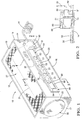
- an air bag module 10 is mounted in a vehicle (not shown) for protection of a vehicle occupant (not shown).
- the module 10 includes a housing 20, an inflatable air bag 27, and an inflator 30 for generating gas to inflate the air bag 27.
- the module 10 is typically mounted on the passenger side of the vehicle, but could also be mounted in other locations on the vehicle.
- the module 10 is secured to the vehicle in any suitable manner.
- the module 10 further includes a movable member 50 and a pyrotechnic device 80 used to vary the amount of inflator gas discharged into the air bag 27, as described in detail hereinafter.
- the housing 20 includes opposing sides walls 14, 15 joined by a bottom wall 16 and opposing end walls 17, 18.
- the end wall 17 includes an end opening 22 for receiving the inflator 30 therein.
- the side walls 14, 15 and end walls 17, 18 cooperatively define a housing opening 19 through which the air bag 27 is deployed.
- the side walls 14, 15 of the housing 20 are positioned adjacent the discharge ports of the inflator 30.
- the housing 20 further includes a plurality of vent openings 21 in the side wall 14. The vent openings 21 are preferably generally aligned with respective discharge ports 32 in the inflator 30, as described further hereinafter.
- the inflator 30 may be of any conventional construction for generating inflator gas to inflate the air bag 27.
- the inflator 30 is preferably a single stage inflator 30 which outputs inflator gas at a single level for inflating the air bag 27.
- the inflator 30 has a generally cylindrical body portion 31 and is insertable through the end opening 22 in the end wall 17 for insertion within the housing 20.
- the inflator 30 has ends which are suitably secured to the housing 20.
- the inflator 30 also includes a plurality of discharge ports 32 which are preferably positioned adjacent the side walls 14, 15 of the housing 20 on opposing sides of the inflator 30 for thrust neutral discharge. Preferably, certain of the discharge ports 32 are generally aligned with the corresponding vent openings 21 in the housing 20.
- the air bag 27 may be of any conventional construction for inflating upon the discharge of inflator gas. Referring to Figure 1, the air bag 27 is shown in the folded condition stored atop the inflator 30 prior to inflator activation. Upon activation of the inflator 30, the air bag 27 is filled with a predetermined amount of inflator gas during inflator activation and deploys out through the housing opening 19 for protection of the vehicle occupant.
- a support member 88 is disposed on the side wall 14 of the housing 20 for holding the movable member 50 and the pyrotechnic device 80.
- the support member 88 may be attached to, such as by welding, or integrally formed with the housing 20.
- the support member 88 includes a frame portion 89 in which the movable member 50 is slidably received.
- the frame member 89 has wall portions 93 for capturing the movable member 50 therein and includes a stop surface 94 against which the movable member 50 is stopped and positioned relative to the vent openings 21 upon firing of the pyrotechnic device 80.
- the support portion 88 further includes an outwardly protruding bracket portion 90 including a support aperture 91 through which the pyrotechnic device 80 is inserted and held in position relative to the movable member 50.
- the movable member 50 is slidably mounted on the support member 88.
- the movable member 50 has a generally plate-like shape and is alignable with the vent openings 21 .
- the movable member 50 is movable relative to the vent openings 21 for opening and closing the vent openings 21 at a predetermined time to control the amount of inflator gas discharged into the air bag 27 and the amount of inflator gas expelled out through the vent openings 21 of the housing 20.
- the movable member 50 has a generally planar outwardly extending portion 52 positioned adjacent the vent openings 21 and a reaction portion 51 which is bent at approximately 90 degrees relative to the outwardly extending portion 52.
- the reaction portion 51 includes a reaction surface 55 facing the pyrotechnic device 80.
- the outwardly extending portion 52 includes a plurality of apertures 53 which are alignable with the vent openings 21.
- the vent openings 21 and the apertures 53 are approximately the same size.
- a pin 49 is disposed on the housing 20 and holds the movable member 50 in a first initial position within the frame portion 89 of the support member 88. It will be appreciated that in the first position, the apertures 53 in the movable member 50 are not aligned with the vent openings 21 on the housing 20 such that the vent openings 21 are preferably entirely closed prior to activation of the inflator 30 as best shown in Figure 1.
- the movable member 50 Upon activation of the pyrotechnic device 80, the movable member 50 is movable to a second position in which the apertures 53 on the movable member 50 are aligned with the vent openings 21 on the housing 20. Thus, when the movable member 50 is in the second position, the vent openings 21 are entirely open.
- the pyrotechnic device 80 or squib preferably contains a chemical which is ignited upon receiving a signal from vehicle sensors (not shown).
- a wire 81 transmits a signal from the sensors to the pyrotechnic device 80 to activate the device 80.
- the device 80 Upon activation, the device 80 produces a pressure wave that presses against the reaction surface 55 of the movable member 50 and quickly forces the movable member 50 from the first position to the second position.
- the pyrotechnic device 80 produces a pressure wave almost instantaneously and preferably within less than 1 ms after activation.
- the movable member 50 is moved from the first position in which the vent openings 21 are entirely closed to the second position in which the vent openings 21 are entirely open almost instantaneously.
- the air bag 27 Prior to activation of the inflator 30, the air bag 27 is stored in a folded condition atop the inflator 30. Also prior to activation of the inflator 30, the movable member 50 is held within the support member 88 in the first position by the pin 49 with the apertures 53 misaligned with the vent openings 21 such that the vent openings 21 are closed. Upon sensing certain predetermined vehicle and occupant conditions, the sensors send a signal to the pyrotechnic device 80 advising the device 80 whether the movable member 50 should be opened at a predetermined time during activation of the inflator 30 so that a certain amount of inflator gas is expelled out through the vent openings 21.
- the pressure wave or flame expelled by the pyrotechnic device 80 reacts against the reaction surface 55 of the movable member 50 and instantaneously shoots the movable member 50 into the second position.
- the movable member 50 shears off the pin 49 and is nearly instantaneously shifted from the first position to the second position.
- the apertures 53 are aligned with the vent openings 21 such that the vent openings 21 are entirely open and inflator gas is expelled out through the vent openings 21.
- the amount of inflator gas discharged into the air bag 27 is variable to a wide range of levels, even with the use of the single stage inflator 30, as will now be described.
- the inflator 30 Upon the sensing of predetermined vehicle conditions by sensors (not shown), the inflator 30 is activated and receives the signal to begin the process of discharging inflator gas at a time which will be designated as 0 milliseconds. It is noted that after the inflator 30 is activated, it may take an additional few milliseconds before the inflator gas actually begins to be discharged into the air bag 27. It will also be appreciated that the inflator gas is discharged over a brief known period of total time for a given inflator 30 after activation.
- inflator gas may be discharged until a total time of 60 milliseconds after activation.
- the amount of time that gas is discharged depends on the type of inflator 30 and is in no way limited to the example of 60 milliseconds.
- the use of a pyrotechnic device 80 enables the vent openings 21 to be opened or closed almost instantaneously upon firing of the device 80.
- the amount of inflator gas discharged into the air bag 27 is easily varied by moving the movable member 80 at a specific predetermined time as enabled by firing the device 80.
- the predetermined time for moving the movable member 50 is determined in response to predetermined conditions of the occupant and vehicle which are sensed by one or more sensors and relayed to the device.
- the predetermined conditions preferably include the mass of the occupant, the position of the occupant, the seat belt usage of the occupant, and the amount and direction of vehicle deceleration.
- a signal is sent to the device 80 which tells the device 80 the predetermined time at which it should fire and move the movable member 50 from the first position to the second position for those particular set of conditions.
- the device 80 can be fired for moving the movable member 50 at a time of 10 ms into inflator activation or 20 ms into inflator activation or at any other time during inflator activation.
- the amount of inflator gas discharged into the air bag 27 can be varied to a wide variety of levels to accommodate numerous conditions with a single inflator 30.
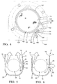
- This can be demonstrated with reference to Figures 5 and 6.
- Figure 5 when the movable member 50 is in the first position and the vent openings 21 are entirely closed, the full amount of inflator gas is delivered into the air bag 27 as shown by the arrows in an upwardly direction towards the air bag 27.
- Figure 6 shows the movable member 50 moved to the second position in which the apertures 53 are aligned with the vent openings 21 such that the vent openings 21 are entirely open.
- the discharge ports 32 on one side of the inflator 30 are aligned with the apertures 53 and vent openings 21 such that about half of the discharging inflator gas is expelled directly out through the vent openings 21 as indicated by the arrow extending out through the vent openings 21.
- the other half of the inflator gas is delivered into the air bag 27 for air bag inflation as indicated by the upwardly directed arrow.
- a predetermined maximum amount of venting can be defined which is the maximum amount of venting that will occur if the vent openings 21 are continuously open during the entire time of inflator gas discharge.
- the device 80 is fired and the movable member is moved to the second position at about 0 ms.
- the maximum amount of venting for each module 10 is set to a predetermined percentage by the size and number of the vent openings 21 on the housing 10.
- the vent openings 21 are substantially aligned with the discharge ports 32 on the inflator 30 such that substantially all of the inflator gas discharged from the discharge ports 32 is expelled out through the corresponding aligned vent openings 21.
- this allows the maximum amount of venting to be achieved with the smallest and least amount of vent openings 21 possible. This may be desirable since the vent openings 21 can affect the ride down characteristics of the air bag 27 after it is inflated. If the vent openings 21 are the smallest possible for the maximum amount of venting, then deflation of the air bag 27 upon occupant interaction is the least affected. Occupant ride down can be controlled in other manners, such as vents on the air bag 27. Alternately, the vent openings 21 can also be tuned to a size that is desirable for occupant ride down as well as maximum venting.
- any variation between the maximum amount of venting and the minimum amount of venting can be achieved by moving the movable member 50 at a predetermined time during inflator 30 activation.
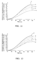
- Figure 11 shows the generic inflation curves for a module 10 having about 40% maximum venting. However, the general shape of the curves will be the same for any amount of maximum venting.
- the curves represent the percent of maximum inflator output delivered to the air bag versus time that the inflator actually discharges gas in milliseconds for a generic module in which the vent openings 21 are normally closed when the movable member 50 is in the first position.
- curve e represents when the movable member 50 remains in the first position during the entire inflator activation.
- Curve e shows that when the vent openings 21 are not opened at all such that there is zero venting, then 100% of inflator output is delivered to the air bag 27.
- curve a shows the situation in which the movable member 50 is moved to the second position during the entire inflator activation.
- Curve a shows that when the vent openings 21 are opened at 0 ms or approximately at the same moment that the inflator 30 is activated, then only 60% of the inflator gas output is delivered to the air bag 27 for inflation and 40% or the maximum amount is expelled out through the vent openings 21 in the housing 20.
- the 40% maximum venting was a predetermined amount based on the size and location of the vent openings 21 and can be varied.
- Curve b depicts that when the movable member 50 is moved to the second position at the predetermined time of 20 ms into inflator 30 activation, then about 70% of the inflator gas output is delivered into the air bag 27 and 30% of the inflator gas is expelled out through the vent openings 21.
- Curve c represents the scenario in which the movable member 50 is moved to the second position at the predetermined time of 30 ms into inflator 30 activation such that about 80% of the inflator gas output is delivered into the air bag 27 and 20% of the inflator gas is expelled out through the vent openings 21.
- curve d represents the scenario in which the movable member 50 is moved to the second position at the predetermined time of 40 ms into inflator 30 activation such that about 90% of the inflator gas output is delivered into the air bag 27 and about 10% of the inflator gas is expelled out through the vent openings 21.
- the curves are merely exemplary and that many other inflation variations are possible depending on the maximum amount of venting and the time at which the device 80 is fired to move the movable member 50. It will be appreciated that the venting could be varied from 0% to 100% with the appropriate number of vent openings 21.
- variable levels of inflation of the air bag 27 can be achieved using a single inflator 30 having only a single level of gas output in combination with vent openings 21 that are preferably either entirely open or entirely closed at a predetermined time during discharge of inflator gas by a movable member 50 is response to activation of a pyrotechnic device 80.
- Almost instantaneous control of the movable member 50 is enabled by the use of the device 80 that reacts nearly instantaneously to the signal received from the vehicle sensors.
- the pyrotechnic device 80 is expendable since it only need be used once, if at all during the lifetime of the inflator 30.
- the pyrotechnic device 80 has been advantageously used to produce mechanical movement, instead of as a typical igniter.
- the movable member 50 need only be moved once during the lifetime of the module 10, if at all, and thus the use of an expendable device 80 is possible. It will also be appreciated that this system provides a relatively simple, cost effective and lightweight solution to providing variable levels of air bag 27 inflation from a single level inflator 30.
- the present invention is easily adaptable to the structure of existing air bag modules, although the additional vehicle sensors would still be needed for sensing the vehicle and occupant conditions.
- this invention uses expendable parts, which are only moved once, if at all, such that reliability over numerous cycles of movement is not a concern.
- the vent openings 21 are either entirely open or entirely closed such that the movable member 50 can be quickly fired open. There is no careful movement of the movable member 50 which is needed for partially opening or partially closing the vent openings 21.
- the inflator 30 is preferably a single stage inflator, it is not limited to use with a single stage inflator.
- the invention could also be used with a dual-stage or multi-stage inflator if desired, but is not necessary to provide variable inflation at nearly any level.
- only one movable member 50, one set of vent openings 21, and one device 80 are shown it will be appreciated that there could be additional devices 80, vent openings 21 and movable members 50 on a given module 10. It will further be appreciated that there need only be at least one vent opening 21 on the housing 20 and that the movable member 50 need not necessarily include apertures 53 since the movable member 50 can simply be moved relative to the vent openings 21 for opening and closing the vent openings 21.
- the embodiment shows the movable member 50 closing the vent openings 21 in the first position prior to inflator activation and opening the vent openings 21 at a predetermined time when moved to the second position upon activation of the device 80, it will be appreciated that the movable member 50 may alternately open the vent openings 21 in the first position prior to inflator activation and close the vent openings 21 at a predetermined time during inflator activation when moved to the second position upon firing of the device 80.
- Figure 12 shows the generic inflation curves for a module having about 40% maximum venting. However, the general shape of the curves will be the same for any amount of maximum venting.
- the curves represent the percent of maximum inflator output delivered to the air bag versus time that the inflator actually discharges gas in milliseconds for a generic module in which the vent openings 21 are normally open when the movable member 50 is in the first position.
- curve a' represents when the movable member 50 remains in the first position during the entire inflator activation.
- Curve a' shows that when the vent openings 21 are never closed, only 60% of the inflator gas output is delivered to the air bag 27 for inflation and 40% or the maximum amount is expelled out through the vent openings 21 in the housing 20.
- curve e' shows the situation in which the movable member 50 is moved to the second position during the entire inflator activation.
- Curve e' shows that when the vent openings 21 are closed at 0 ms or approximately at the same moment that the inflator 30 is activated, then 100% of inflator output is delivered to the air bag 27.
- the 40% maximum venting was a predetermined amount based on the size and location of the vent openings 21 and can be varied.
- Curve d' depicts that when the movable member 50 is moved to the second position at the predetermined time of 20 ms into inflator 30 activation, then about 90% of the inflator gas output is delivered into the air bag 27 and 10% of the inflator gas is expelled out through the vent openings 21.
- Curve c' represents the scenario in which the movable member 50 is moved to the second position at the predetermined time of 30 ms into inflator 30 activation such that about 80% of the inflator gas output is delivered into the air bag 27 and 20% of the inflator gas is expelled out through the vent openings 21.
- curve b' represents the scenario in which the movable member 50 is moved to the second position at the predetermined time of 40 ms into inflator 30 activation such that about 70% of the inflator gas output is delivered into the air bag 27 and about 30% of the inflator gas is expelled out through the vent openings 21.
- the curves are merely exemplary and that many other inflation variations are possible depending on the maximum amount of venting and the time at which the device 80 is fired to move the movable member 50. It will be appreciated that the venting could be varied from 0% to 100% with the appropriate number of vent openings 21.
- variable levels of inflation of the air bag 27 can be achieved using a single inflator 30 having only a single level of gas output in combination with vent openings 21 that are preferably entirely open or entirely closed at a predetermined time during discharge of inflator gas by a movable member 50 in response to activation of a pyrotechnic device 80.
- Figure 13 shows a comparison of the shape of the inflation curve for the situation when the vent openings 21 are either initially normally closed, curve c, or normally opened, curve c'.
- the movable member 50 is moved to the second position at the predetermined time of 30 ms into inflator 30 activation such that about 80% of the inflator gas output is delivered into the air bag 27 and about 20% of the inflator gas is expelled out through the vent openings 21.
- the shape of the inflation curve depends on whether the vent openings 21 are normally open or normally closed.
- the inflation curve c' has a gentler initial slope than the curve c in which the vent openings 21 were initially closed.
- this is yet another way in which the inflation of the air bag 27 can be controlled using the movable member 50 and device 80. It will be appreciated that if a gentler initial slope is desired for lesser initial air bag inflation, then the vent openings 21 can be normally opened in the first position and then closed in the second position upon activation of the device 80. Alternately, if a sharper initial slope is desired for greater initial air bag inflation, then the vent openings 21 can be normally closed in the first position and then opened in the second position upon activation of the device 80.
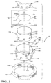
- FIGS 3 and 4 show an alternate embodiment of the invention having a movable member 150 which is a rotatable ring.
- This version is particularly well-adapted for use on the driver's side of a vehicle. Similar features will be denoted with similar numerals increased by 100.
- An air bag module 110 is mounted in a vehicle steering wheel (not shown) for protection of a vehicle occupant (not shown).
- the module 110 includes a housing 120, an inflatable air bag 127, and an inflator 130 for generating gas to inflate the air bag 127.
- the module 110 is typically mounted on the driver's side of the vehicle, but could also be mounted in other locations on the vehicle.
- the module 110 is secured to the vehicle in any suitable manner, such as by a base plate 160.
- the module 110 further includes a movable member 150 being a rotatable ring and a pyrotechnic device 180 used to vary the amount of inflator gas discharged into the air bag 127, as described in detail hereinafter.
- the housing 120 includes a generally circular side wall 114 closed by a bottom wall 116.
- the side wall 114 defines a housing opening 119 through which gas is discharged to inflate the air bag 127.
- the side wall 114 of the housing 120 is positioned adjacent the discharge ports 132 of the inflator 130.
- the housing 120 further includes a plurality of vent openings 121 in the side wall 114.
- the vent openings 121 are preferably generally aligned with respective discharge ports 132 in the inflator 130 such that discharging gas from the inflator is expelled directly out through the vent openings 121 when they are open.
- the module 110 includes a generally flat base plate 160 to which the air bag 127, inflator 130, and housing 120 are attached.
- the base plate 160 includes a base plate opening 161 for receiving the inflator 130 partially therethrough during assembly.
- the base plate 160 is preferably connected to the vehicle such as by fasteners (not shown) to connect the module 110 to the vehicle.
- the inflator 130 may be of any conventional construction for generating inflator gas to inflate the air bag 127.
- the inflator 130 is preferably a single stage inflator 130 which outputs inflator gas at a single level for inflating the air bag 127.
- the inflator 30 has a generally circular body portion 131 and is insertable through the base plate opening 161 for insertion within the housing 120.
- the inflator 130 may include a flange (not shown) for connection to the base plate 160.
- the inflator 130 also includes a plurality of discharge ports 132 which are preferably positioned adjacent the side walls 114 of the housing 120 and are spaced around the body portion 131 for thrust neutral discharge. Preferably, certain of the discharge ports 132 are generally aligned with the corresponding vent openings 121 in the housing 120.
- the air bag 127 may be of any conventional construction for inflating upon the discharge of inflator gas. Referring to Figure 3, the air bag 127 is stored atop the inflator 130 prior to inflator activation.
- the air bag 127 includes an air bag retainer 128 located around a mouth portion 129 of the air bag 127.
- the air bag retainer 128 connects the air bag 127 to the base plate 160.
- the air bag 127 is filled with a predetermined amount of inflator gas during inflator activation and deploys out through a cover (not shown) on the steering wheel for protection of the vehicle occupant.
- the housing 120 includes a radially outwardly projecting support member 188 including a wall portion 193 having a support aperture 191 for holding the pyrotechnic device 180 therein.
- the support member 188 includes stop surface 194 against which the movable member 150 is stopped during rotation and positioned relative to the vent openings 121 upon firing of the pyrotechnic device 180.
- the support member 188 may be attached to, such as by welding, or integrally formed with the housing 120.
- the movable member 150 is slidably mounted between the housing 120 and the inflator 130.
- the movable member 150 is captured during assembly between the housing 120 and the base plate 160.
- the movable member 150 is preferably shaped like a ring and is alignable with the vent openings 121 by rotational movement.
- the movable member 150 is movable relative to the vent openings 121 for opening and closing the vent openings 121 at a predetermined time to control the amount of inflator gas discharged into the air bag 127 and the amount of inflator gas expelled out through the vent openings 121 of the housing 120.
- the movable member 150 includes a generally circular wall portion 151 and a radially outwardly projecting tab portion 152 which is bent at approximately 90 degrees relative to the wall portion 151.
- the tab portion 152 includes a reaction surface 155 facing the pyrotechnic device 180.
- the wall portion 151 includes a plurality of apertures 153 which are alignable with the vent openings 121.
- a clip 149 extends between the device 180 and the tab portion 152 and holds the movable member 150 in an initial first position. It will be appreciated that in the first position, the apertures 153 in the movable member 150 are preferably not aligned with the vent openings 121 on the housing 120 such that the vent openings 121 are preferably entirely closed prior to activation of the inflator 130. Upon activation of the pyrotechnic device 180, the movable member 150 is rotated to a second position in which the apertures 153 on the movable member 150 are aligned with the vent openings 121 on the housing 120. Thus, when the movable member 150 is in the second position, the vent openings 121 are entirely open.
- the pyrotechnic device 180 or squib preferably contains a chemical which is ignited upon receiving a signal from vehicle sensors (not shown).
- a wire 181 transmits a signal from the sensors to the pyrotechnic device 180 to activate the device 180.
- the device 180 Upon activation, the device 180 produces a pressure wave that presses against the reaction surface 155 of the movable member 150 and quickly forces the movable member 150 from the first position to the second position.
- the pyrotechnic device 180 produces a pressure wave almost instantaneously and preferably within less than 1 ms after activation.
- the movable member 150 is rotated from the first position in which the vent openings 121 are entirely closed to the second position in which the vent openings 121 are entirely open almost instantaneously.
- the sensors Upon sensing certain predetermined vehicle and occupant conditions, the sensors send a signal to the pyrotechnic device 180 advising the device 180 whether the movable member 150 should be moved at a predetermined time during activation of the inflator 130 so that a certain amount of inflator gas is expelled out through the vent openings 121.
- the pyrotechnic device 180 advising the device 180 whether the movable member 150 should be moved at a predetermined time during activation of the inflator 130 so that a certain amount of inflator gas is expelled out through the vent openings 121.
- the pressure wave or flame expelled by the device 180 reacts against the reaction surface 155 of the tab portion 152 of the movable member 150 and instantaneously rotates the movable member 150 into the second position.
- the force of the movable member 150 breaks off the clip 149 and is nearly instantaneously shifted from the first position to the second position.
- the tab portion 152 engages the stop surface 194 which limits rotational movement of the movable member 150 upon activation of the device 180.
- the apertures 153 are aligned with the vent openings 121 such that the vent openings 121 are entirely open and inflator gas is expelled out through the vent openings 121.
- variable levels of inflation of the air bag 127 can be achieved using a single inflator 130 having only a single level of gas output in combination with vent openings 121 that are preferably entirely opened or entirely closed at a predetermined time during discharge of inflator gas by the movable member 150 is response to activation of a pyrotechnic device 180.
- the predetermined time for moving the movable member 150 is determined in response to predetermined conditions of the occupant and vehicle which are sensed by one or more sensors and relayed to the device 180.
- movable member 150 being a rotatable ring is shown as being a continuous circle, it will be appreciated that the ring could be discontinuous and need not make a complete circle. Although only one movable member 150, one set of vent openings 121, and one device 180 are shown it will be appreciated that there could be additional devices 180, vent openings 121 and movable members 150 on a given module 110.
- vent opening 121 there need only be at least one vent opening 121 on the housing 120 and that the movable member 150 need not necessarily include apertures 153 since the movable member 150 can simply be moved relative to the vent opening 121 for opening and closing the vent opening 121.
- the embodiment shows the movable member 150 closing the vent openings 121 in the first position prior to inflator activation and opening the vent openings 121 at a predetermined time when moved to the second position upon activation of the device 180, it will be appreciated that the movable member 150 may alternately open the vent openings 121 in the first position prior to inflator activation and close the vent openings 121 at a predetermined time during inflator activation when moved to the second position.
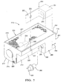
- FIG. 7 Another alternate embodiment of the invention will now be described with reference to Figure 7.
- the embodiment of Figure 7 will be described using similar references numerals increased by 200.
- the embodiment of Figure 7 differs from the above embodiments in that the movable member 250 is positioned inside of the housing 220 and the vent openings 221 are initially opened.
- an air bag module 210 is mounted in a vehicle (not shown) for protection of a vehicle occupant (not shown).
- the module 210 includes a housing 220, an inflatable air bag 227, and an inflator 230 for generating gas to inflate the air bag 227.
- the module 210 is typically mounted on the passenger side of the vehicle, but could also be mounted in other locations on the vehicle.
- the module 210 is secured to the vehicle in any suitable manner.
- the module 210 further includes a movable member 250 and a pyrotechnic device 280 used to vary the amount of inflator gas discharged into the air bag 227, as described in detail hereinafter.
- the housing 220 includes opposing sides walls 214, 215 joined by a bottom wall 216 and opposing end walls 217, 218.
- the end wall 217 includes an end opening 222 for receiving the inflator 230 therein.
- the side walls 214, 215 and end walls 217, 218 cooperatively define a housing opening 219 through which the air bag 227 is deployed.
- the side wall 214 of the housing 220 includes an indented portion 223 positioned adjacent the discharge ports 232 of the inflator 230.
- the housing 220 further includes a single vent opening 221 in the side wall 214.
- the vent opening 221 is located on the indented portion 223 of the side wall 214 and is preferably directly aligned with corresponding discharge port 232 in the inflator 230 such that substantially all of the gas discharged from the aligned discharge port 232 is expelled out through the vent opening 221 when open.
- the inflator 230 may be of any conventional construction for generating inflator gas to inflate the air bag 227.
- the inflator 230 is preferably a single stage inflator 230 which outputs inflator gas at a single level for inflating the air bag 227.
- the inflator 230 has a generally cylindrical body portion 231 and is insertable through the end opening 222 in the end wall 217 for insertion within the housing 220.
- the inflator 230 has ends which are suitably secured to the housing 220.
- the inflator 230 also includes an end portion 233 having three discharge ports 232 spaced evenly apart around the end portion 233 for thrust neutral discharge.
- one of the discharge ports 232 which can be seen in Figure 7, is directly aligned with the corresponding vent opening 221 in the housing 220.
- the maximum amount of venting of the module 210 is about 33% since one-third of the maximum amount of gas will be expelled out through the vent opening 221 if the vent opening 221 remains open during the entire time of inflator activation and is never closed by the movable member 250.
- the air bag 227 may be of any conventional construction for inflating upon the discharge of inflator gas.
- the air bag 227 is shown in the folded condition stored atop the inflator 230 prior to inflator activation. Upon activation of the inflator 230, the air bag 227 is filled with a predetermined amount of inflator gas during inflator activation and deploys out through the housing opening 219 for protection of the vehicle occupant.
- the housing 220 includes an outwardly projecting pocket portion 288 disposed on the side wall 214 for holding the movable member 250 and the pyrotechnic device 280 therein.
- the pocket portion 288 is preferably integrally formed with the housing 220.
- the pocket portion 288 has a length which is greater than a length of a reaction portion 251 of the movable member 250.
- opposing wall portions 293 of the pocket portion 288 are spaced apart such there is a gap 289 created between the movable member 250 and one of the wall portions 293 when the reaction portion 251 of the movable member 250 is seated into the pocket portion 288. This enables the movable member 250 to be moved from a first position to a second position, as described further hereinafter.
- the pocket portion 288 includes a stop surface 294 on one wall portion 293 against which the movable member 250 is stopped and positioned relative to the vent openings 221 upon firing of the pyrotechnic device 280.
- the opposing wall portion 293 of the pocket portion 288 includes a support aperture 291 through which the pyrotechnic device 280 is inserted and held in position relative the movable member 250. It will be appreciated that the movable member 250 could be moved in the opposite direction with the stop surface 294, device 280 and support aperture 291 located on the opposite wall portions 293.
- the movable member 250 is seated in the pocket portion 288 and is slidable within the pocket portion 288 when the device 280 is fired.
- the movable member 250 is movable relative to the vent opening 221 for opening and closing the vent opening 221 at a predetermined time to control the amount of inflator gas discharged into the air bag 227 and the amount of inflator gas expelled out through the vent opening 221 of the housing 220.
- the movable member 250 has a generally planar outwardly extending portion 252 positioned adjacent the vent openings 221 and an enlarged reaction portion 251.
- the reaction portion 251 includes a reaction surface 255 facing the pyrotechnic device 280.
- the outwardly extending portion 252 includes an aperture 253 which is normally aligned with the vent opening 221 for opening the vent opening 221.
- the pyrotechnic device 280 or squib preferably contains a chemical which is ignited upon receiving a signal from vehicle sensors (not shown).
- a wire 281 transmits a signal from the sensors to the pyrotechnic device 280 to activate the device 280.
- the device 280 acts as a pin that holds the movable member 250 in a first initial position within the pocket portion 288.
- the device 280 produces a pressure wave that presses against the reaction surface 255 of the movable member 250 and quickly forces the movable member 250 from a first position in which there is a gap 289 between the movable member 250 and the stop surface 294 into a second position in which the movable member 250 engages the stop surface 294.
- the aperture 253 in the movable member 250 is aligned with the vent opening 221 on the housing 220 such that the vent opening 221 is preferably entirely open.
- the movable member 250 is movable to the second position in which the aperture 253 on the movable member 250 is aligned with the vent opening 221 on the housing 220.
- the vent opening 221 is entirely closed.
- the gap 289 is sized such that the movable member 250 can move a sufficient amount to close the vent opening 221.
- the pyrotechnic device 280 produces a pressure wave almost instantaneously and preferably within less than 1 ms after activation such that the exact timing of the venting can be controlled to enable control of the amount of inflator gas delivered to the air bag 227.
- the amount of inflator gas discharged into the air bag 227 is variable to an almost unlimited range of levels, even with the use of the single stage inflator 230.
- the inflator 230 Upon the sensing of predetermined vehicle conditions by sensors (not shown), the inflator 230 is activated and receives the signal to begin the process of discharging inflator gas at a time designated as 0 milliseconds.
- the use of a pyrotecluiic device 280 enables the movable member 250 to be moved and the vent openings 221 to be changed from open to closed almost instantaneously upon firing of the device 280.
- the amount of inflator gas discharged into the air bag 227 is easily varied by moving the movable member 250 at different predetermined times during inflator activation.
- the predetermined time for moving the movable member 250 is determined in response to predetermined conditions of the occupant and vehicle which are sensed by one or more sensors and relayed to the device. If the device 280 is never fired and the movable member 250 remains in the first position, the discharge port 232 remains aligned with the vent opening 221 and aperture 253 and expels all of its gas directly out through the vent opening 221 such that a maximum of about one-third of the inflator gas may be vented and the other two-thirds is delivered into the air bag 227.
- the movable member 250 is moved to the second position and the vent opening 221 is closed and the full amount of inflator gas is delivered to the air bag 227. It will further be appreciated that the device 280 could be fired to move the movable member 250 at a variety of times during inflator gas discharge so that more than two-thirds but less than 100% of the gas is delivered to the air bag 227.
- vent opening 221 is directly aligned with the corresponding discharge port 232 on the inflator 230 such that substantially all of the inflator gas discharged from the corresponding discharge port 332 is expelled out through the corresponding aligned vent opening 221.
- this allows the maximum amount of venting to be achieved with the smallest and least amount of vent openings 221 possible.
- variable levels of inflation of the air bag 227 can be achieved using a single inflator 230 having only a single level of gas output in combination with a single vent opening 221 that is preferably entirely opened or entirely closed at a predetermined time during discharge of inflator gas by a movable member 250 in response to activation of a pyrotechnic device 280.
- Almost instantaneous control of the movable member 250 is enabled by the use of the device 280 that reacts nearly instantaneously to the signal received from the vehicle sensors.
- this system provides a relatively simple, cost effective and lightweight solution to providing variable levels of air bag 227 inflation from a single level inflator 230.
- the inflator 230 is preferably a single stage inflator, it is not limited to use with a single stage inflator.
- the movable member 250 need not necessarily include apertures 253 since the movable member 250 can simply be moved relative to the vent opening 221 for opening and closing the vent opening 221.
- the embodiment shows the movable member 250 opening the vent opening 221 in the first position prior to inflator activation and closing the vent opening 221 at a predetermined time when moved to the second position upon activation of the device 280, it will be appreciated that the movable member 250 may alternately close the vent opening 221 in the first position prior to inflator activation and open the vent opening 221 at a predetermined time during inflator activation when moved to the second position upon firing of the device 280.
- an air bag module 310 is mounted in a vehicle (not shown) for protection of a vehicle occupant (not shown).
- the module 310 includes a housing 320, an inflatable air bag (not shown), and an inflator 230 for generating gas to inflate the air bag.
- the module 310 is typically mounted on the driver's side of the vehicle, but could also be mounted in other locations on the vehicle.
- the module 310 is secured to the vehicle in any suitable manner.
- the module 310 further includes a movable member 350 and a pyrotechnic device 380 used to vary the amount of inflator gas discharged into the air bag, as described in detail hereinafter.
- the housing 320 includes a generally circular side wall 314 closed by a bottom wall 316.
- the side wall 314 defines a housing opening 319 through which inflator gas is discharged into the air bag.
- the side wall 314 of the housing 320 is positioned adjacent the discharge ports 332 of the inflator 330.
- the housing 320 further includes a single vent opening 321 in the side wall 314.
- the vent opening 321 is preferably directly aligned with a corresponding discharge port 332 in the inflator 330 such that substantially all of the gas discharged from the discharge port 332 is expelled out through the vent opening 321 when open.
- the inflator 330 may be of any conventional construction for generating inflator gas to inflate the air bag.
- the inflator 330 is preferably a single stage inflator 330 which outputs inflator gas at a single level for inflating the air bag.
- the inflator 330 has a generally cylindrical body portion 331 and is insertable through the housing opening 319 into the housing 320.
- the inflator 330 includes a radially outwardly projecting inflator flange 334 which is suitably secured to the housing 320.
- the inflator 330 also preferably includes three discharge ports 332 spaced evenly apart around the body portion 331 for thrust neutral discharge.
- one of the discharge ports 332 is directly aligned with the vent opening 321 in the housing 320.
- the maximum amount of venting of the module 310 is about 33% since about one-third of the maximum amount of gas will be expelled out through the vent opening 321 if the vent opening 321 remains open during the entire time of inflator activation and is never closed by the movable member 350.
- the module 310 may include a base plate to which the air bag, inflator flange 334, and housing 320 are attached.
- the air bag may be of any conventional construction for inflating upon the discharge of inflator gas.
- the air bag preferably has a mouth portion that is joined to the base plate and receives inflator gas delivered through the housing opening 319.
- the air bag Upon activation of the inflator 330, the air bag is filled with a predetermined amount of inflator gas during inflator activation and deploys out through a cover (not shown) in a steering wheel (not shown) for protection of the vehicle occupant.
- the housing 320 includes an outwardly projecting pocket portion 388 preferably extending downwardly from the bottom wall 316 for holding the movable member 350 and the pyrotechnic device 380 therein.
- the pocket portion 388 is preferably integrally formed with the housing 320.
- the pocket portion 388 has a height which is greater than a height of a reaction portion 351 of the movable member 350.
- a gap 389 is created between the movable member 350 and the upper end of the pocket portion 388 when the reaction portion 351 of the movable member 350 is seated in the pocket portion 388. This enables the movable member 350 to be moved from a first position to a second position, as described further hereinafter.
- a bottom wall portion 393 of the pocket portion 388 includes a support aperture 391 through which the pyrotechnic device 380 is inserted and held in position relative the movable member 350.
- the housing 320 includes a stop surface 394 against which the movable member 350 is stopped and positioned relative to the vent openings 321 upon firing of the pyrotechnic device 380.
- the stop surface 394 may be provided as a support plate 396 which is inserted in the housing 320 after the movable member 350 and prior to the inflator 330.
- the movable member 350 is seated in the pocket portion 388 and is slidable within the pocket portion 388 when the device 380 is fired.
- the movable member 350 is movable relative to the vent opening 321 for opening and closing the vent opening 321 at a predetermined time to control the amount of inflator gas discharged into the air bag and the amount of inflator gas expelled out through the vent opening 321 of the housing 320.
- the movable member 350 has a generally planar upwardly extending portion 352 positioned adjacent the vent opening 321 and an enlarged reaction portion 351.
- the reaction portion 351 includes a reaction surface 355 facing the pyrotechnic device 380.
- the outwardly extending portion 352 includes an aperture 353 which is normally aligned with the vent opening 321 for opening the vent opening 321.
- the pyrotechnic device 380 or squib preferably contains a chemical which is ignited upon receiving a signal from vehicle sensors (not shown).
- a wire 381 transmits a signal from the sensors to the pyrotechnic device 380 to activate the device 380.
- the device 380 acts as a pin that holds the movable member 350 in a first initial position within pocket portion 388 as shown in Figure 9.
- the device 380 Upon activation as shown in Figure 10, the device 380 produces a pressure wave or flame that presses against the reaction surface 355 of the movable member 350 and quickly forces the movable member 350 from a first position in which there is a gap 389 between the reaction portion 351 and the stop surface 394 into a second position in which the reaction portion 351 engages the stop surface 394.
- the movable member 350 preferably includes a snap-locking feature 335 which snaps over the support plate 396 and holds up the movable member 350 in the second position.
- the aperture 353 in the movable member 350 is aligned with the vent opening 321 on the housing 320 such that the vent opening 321 is preferably entirely open prior to activation of the inflator 330.
- the movable member 350 is shot upwardly to the second position in which the aperture 353 on the movable member 350 is aligned with the vent openings 321 on the housing 320.
- the vent opening 321 is entirely closed.
- the gap 389 is sized such that the movable member 350 can move a sufficient amount to close the vent opening 321.
- the pyrotechnic device 380 produces a pressure wave almost instantaneously and preferably within less than 1 ms after activation such that the exact timing of the venting can be controlled to enable control of the amount of inflator gas delivered to the air bag.
- the amount of inflator gas discharged into the air bag is variable to a wide range of levels, even with the use of the single stage inflator 330.
- the inflator 330 Upon the sensing of predetermined vehicle conditions by sensors (not shown), the inflator 330 is activated and receives the signal to begin the process of discharging inflator gas.
- the use of a pyrotechnic device 380 enables the movable member 350 to be moved and the vent openings 321 to be changed from open to closed almost instantaneously upon firing of the device 380.
- the amount of inflator gas discharged into the air bag is easily varied by moving the movable member 350 at different predetermined times during inflator activation.
- the predetermined time for moving the movable member 350 is determined in response to predetermined conditions of the occupant and vehicle which are sensed by one or more sensors and relayed to the device 380. If the device 380 is never fired and the movable member 350 remains in the first position, the discharge port 332 remains aligned with the vent opening 321 and the aperture 353 and expels all of its gas directly out through the vent opening 321 such that a maximum of about one-third of the inflator gas may be vented and the other two-thirds is delivered into the air bag.
- the movable member 350 is moved to the second position and the vent opening 321 is closed and the full amount of inflator gas is delivered to the air bag. It will further be appreciated that the device 380 could be fired and move the movable member 350 at a variety of times during inflator gas discharge so that more than two-thirds but less than 100% of the gas is delivered to the air bag.
- vent opening 321 is directly aligned with the corresponding discharge port 332 on the inflator 330 such that substantially all of the inflator gas discharged from the discharge port 332 is expelled out through the corresponding aligned vent opening 321.
- this allows the maximum amount of venting to be achieved with the smallest and least amount of vent openings 321 possible.
- variable levels of inflation of the air bag can be achieved using a single inflator 330 having only a single level of gas output in combination with a single vent opening 321 that is preferably entirely opened or entirely closed at a predetermined time during discharge of inflator gas by a movable member 350 is response to activation of a pyrotechnic device 380.
- Almost instantaneous control of the movable member 350 is enabled by the use of the device 380 that reacts nearly instantaneously to the signal received from the vehicle sensors.
- this system provides a relatively simple, cost effective and lightweight solution to providing variable levels of air bag inflation from a single level inflator 330.
- the inflator 330 is preferably a single stage inflator, it is not limited to use with a single stage inflator.
- the movable member 350 need not necessarily include aperture 353 since the movable member 350 can simply be moved relative to the vent opening 321 for opening and closing the vent opening 321.
- the embodiment shows the movable member 350 opening the vent opening 321 in the first position prior to inflator activation and closing the vent opening 321 at a predetermined time when moved to the second position upon activation of the device 380, it will be appreciated that the movable member 350 may alternately close the vent opening 321 in the first position prior to inflator activation and open the vent opening 321 at a predetermined time during inflator activation when moved to the second position upon firing of the device 380.
Landscapes
- Engineering & Computer Science (AREA)
- Mechanical Engineering (AREA)
- Physics & Mathematics (AREA)
- Fluid Mechanics (AREA)
- Air Bags (AREA)
Claims (36)
- Module d'airbag (10) destiné à retenir un occupant dans un véhicule, le module d'airbag (10) comprenant :caractérisé par un boítier (20) ayant une paroi (14) adjacente à l'orifice d'évacuation (32) du dispositif de gonflage (30), le boítier (20) incluant au moins une ouverture de sortie d'air (21) ; un élément mobile (50) qui peut s'aligner avec l'ouverture de sortie d'air (21), l'élément mobile (50) pouvant se déplacer par rapport à l'ouverture de sortie d'air (21) pour ouvrir et fermer l'ouverture de sortie d'air (21) à un moment prédéterminé pendant l'activation du dispositif de gonflage (30), afin de contrôler la quantité de gaz de dispositif de gonflage évacué dans l'airbag (27) et la quantité de gaz de dispositif de gonflage expulsé vers l'extérieur à travers l'ouverture de sortie d' air (21) du boítier (20) ; etun airbag (27) ;un dispositif de gonflage (30) que l'on peut actionner pour libérer un gaz de dispositif de gonflage destiné à gonfler l'airbag (27), le dispositif de gonflage (30) ayant au moins un orifice d'évacuation (32) à travers lequel le gaz de dispositif de gonflage est évacué ;
un dispositif (80) que l'on peut activer pendant l'activation du dispositif de gonflage (30) pour déplacer l'élément mobile (50) par rapport à l'ouverture de sortie d'air (21) au moment prédéterminé pendant l'activation du dispositif de gonflage (30),
dans lequel l'ouverture de sortie d'air (21) et le au moins un orifice d'évacuation (32) sont sensiblement alignés l'un avec l'autre, de telle sorte que sensiblement l'intégralité du gaz de dispositif de gonflage évacué depuis le au moins un orifice d'évacuation (32) est expulsé vers l'extérieur à travers l'ouverture de sortie d'air (21), lorsque l'élément mobile (50) est positionné pour ouvrir l'ouverture de sortie d'air (21). - Module d'airbag (10) selon la revendication 1, caractérisé en ce que le dispositif de gonflage peut également comprendre au moins un autre orifice d'évacuation à travers lequel le gaz de dispositif de gonflage est évacué, ledit au moins un autre orifice d'évacuation n'étant pas sensiblement aligné avec l'ouverture de sortie d'air (21).
- Module d'airbag (10) selon la revendication 1, caractérisé en ce que le dispositif (80) est un dispositif pyrotechnique.
- Module d'airbag (10) selon la revendication 1, caractérisé en ce que le dispositif (80) est capable de générer une pression pour déplacer l'élément mobile (50).
- Module d'airbag (10) selon la revendication 1, caractérisé en ce que l'élément mobile (50) inclut une surface de réaction (55) et dans lequel le dispositif (80) est un dispositif pyrotechnique capable de générer une pression contre la surface de réaction (55) de l'élément mobile (50) pour déplacer l'élément mobile (50) par rapport à l'ouverture de sortie d'air (21).
- Module d'airbag (10) selon la revendication 1, caractérisé en ce que le dispositif (80) est un dispositif pyrotechnique et dans lequel le dispositif pyrotechnique est mis à feu pendant l'activation du dispositif de gonflage (30) pour déplacer l'élément mobile (50) par rapport à l'ouverture de sortie d'air (21), à un moment prédéterminé pour contrôler la quantité de gaz de dispositif de gonflage évacué dans l'airbag (27).
- Module d'airbag (10) selon la revendication 1, caractérisé en ce que le moment prédéterminé pour déplacer l'élément mobile (50) est déterminé en réponse aux états prédéterminés de l'occupant et du véhicule.
- Module d'airbag (10) selon la revendication 7, caractérisé en ce que le véhicule inclut une ceinture de sécurité et dans lequel les états prédéterminés incluent la masse de l'occupant, la position de l'occupant, l'usage de la ceinture de sécurité de l'occupant et la décélération du véhicule.
- Module d'airbag (10) selon la revendication 1, caractérisé en ce que l'élément mobile (50) ferme l'ouverture de sortie d'air (21) pratiquée dans le boítier (20) avant l'activation du dispositif (80).
- Module d'airbag (10) selon la revendication 1, caractérisé en ce que l'élément mobile (50) ouvre l'ouverture de sortie d'air (21) pratiquée dans le boítier (20) avant l'activation du dispositif (80).
- Module d'airbag (10) selon la revendication 1, caractérisé en ce que l'élément mobile (50) est positionné dans une première position pour fermer l'ouverture de sortie d'air (21), de telle sorte qu'une quantité totale de gaz de dispositif de gonflage est normalement évacuée dans l'airbag (27) et dans lequel l'élément mobile (50) peut se déplacer vers une seconde position, afin d'ouvrir l'ouverture de sortie d'air (21) à un moment prédéterminé après l'activation du dispositif de gonflage (30) pour réduire la quantité de gaz de dispositif de gonflage évacué dans l'airbag (27).
- Module d'airbag (10) selon la revendication 11, caractérisé en ce que le dispositif de gonflage comprend également au moins un autre orifice d'évacuation à travers lequel le gaz de dispositif de gonflage est évacué, ledit au moins un autre orifice d'évacuation n'étant pas sensiblement aligné avec l'ouverture de sortie d'air (21).
- Module d'airbag (10) selon la revendication 1, caractérisé en ce que l'élément mobile (50) est positionné dans une première position pour ouvrir l'ouverture de sortie d'air (21), de telle sorte qu'au moins une partie du gaz de dispositif de gonflage est normalement expulsé vers l'extérieur à travers l'ouverture de sortie d'air (21) et dans lequel l'élément mobile (50) peut se déplacer vers une seconde position pour fermer l'ouverture de sortie d'air (21) à un moment prédéterminé pendant l'activation du dispositif de gonflage (30) pour augmenter la quantité de gaz de dispositif de gonflage évacuée dans l'airbag (27).
- Module d'airbag (10) selon la revendication 13, caractérisé en ce que le dispositif de gonflage comprend également au moins un autre orifice d'évacuation à travers lequel le gaz de dispositif de gonflage est évacué, ledit au moins un autre orifice d'évacuation n'étant pas sensiblement aligné avec l'ouverture de sortie d'air (21).
- Module d'airbag (10) selon la revendication 1, caractérisé en ce que l'élément mobile (50) inclut une ouverture (53) et dans lequel l'ouverture (53) peut s'aligner avec l'ouverture de sortie d'air (21) pour ouvrir l'ouverture de sortie d'air (21).
- Module d'airbag (10) selon la revendication 1, caractérisé en ce que le dispositif de gonflage (30) inclut une pluralité d'orifices d'évacuation (32) et dans lequel le boítier (20) inclut une seule ouverture de sortie d'air (21) sensiblement alignée avec l'un des orifices d'évacuation (32), de telle sorte que sensiblement l'intégralité du gaz de dispositif de gonflage évacué à partir de l'orifice d'évacuation (32) aligné avec l'ouverture de sortie d'air (21) est expulsé vers l'extérieur à travers l'ouverture de sortie d'air (21) lorsque l'élément mobile (50) ouvre l'ouverture de sortie d'air (21).
- Module d'airbag (10) selon la revendication 1, caractérisé en ce que le moment prédéterminé pour déplacer l'élément mobile (50) est 0-40 millisecondes après l'activation du dispositif de gonflage (30).
- Module d'airbag (10) selon la revendication 1, caractérisé en ce que l'élément mobile (50) a une forme généralement semblable à un plateau et dans lequel le module (10) inclut une goupille (49) qui maintient l'élément mobile (50) dans une première position et dans lequel l'activation du dispositif (80) force l'élément mobile (50) depuis la première position vers une seconde position et dans lequel la goupille (49) est fendue lorsque l'élément mobile (50) se trouve dans la seconde position.
- Module d'airbag (110) selon la revendication 1; caractérisé en ce que l'élément mobile (150) est une bague pouvant tourner et dans lequel l'élément mobile (150) tourne par rapport au dispositif de gonflage (130) et au boítier (120) au moment de l'activation du dispositif (180).
- Module d'airbag (110) selon la revendication 19, caractérisé en ce que l'élément mobile (150) étant une bague pouvant tourner inclut une languette faisant saillie vers l'extérieur radialement (152) et dans lequel le boítier (120) inclut une surface d'arrêt faisant radialement saillie vers l'extérieur (194) et dans lequel la languette (152) s'engage sur la surface d'arrêt (194) pour limiter le mouvement de rotation de l'élément mobile (150) au moment de l'activation du dispositif (180).
- Module d'airbag (110) selon la revendication 1, caractérisé en ce que l'élément mobile (150) est positionné entre la paroi (114) du boítier (120) et le dispositif de gonflage (130).
- Module d'airbag (210) selon la revendication 1, caractérisé en ce que le boítier (220) inclut une partie de pochette intérieure (288) dans laquelle l'élément mobile (250) est logé.
- Module d'airbag (210) selon la revendication 22, caractérisé en ce que l'élément mobile (250) inclut une partie de réaction (251) permettant de recevoir le dispositif (280) à l'intérieur de celle-ci et une partie qui s'étend vers l'extérieur (252) positionnée de manière adjacente à l'ouverture de sortie d'air (221).
- Module d'airbag (210) selon la revendication 23, caractérisé en ce que la partie de réaction (251) est positionnée à l'intérieur de la partie de poche (288).
- Module d'airbag (210) selon la revendication 24, caractérisé en ce que la partie de poche (288) a une longueur supérieure à une longueur de la partie de réaction (251) de telle sorte que, au moment de l'activation du dispositif (280), la partie de réaction (251) se décale à l'intérieur de la partie de poche (288) pour permettre le mouvement de la partie s'étendant vers l'extérieur (252) de l'élément mobile (250) par rapport à l'ouverture de sortie d'air (221).
- Module d'airbag (210) selon la revendication 23, caractérisé en ce que la partie de poche (288) inclut une surface d'arrêt (294) qui limite le mouvement de la partie de réaction (251) au moment de l'activation du dispositif (280) et positionne correctement la partie qui s'étend vers l'extérieur (252) de l'élément mobile (250) par rapport à l'ouverture de sortie d'air (221).
- Module d'airbag (210) selon la revendication 22, caractérisé en ce que la partie de poche (288) inclut une ouverture de poche (291) à travers laquelle le dispositif (280) peut être inséré dans l'élément mobile (250) après insertion de l'élément mobile (250) dans le boítier (220).
- Module d'airbag (10) selon la revendication 1, caractérisé en ce que le module (10) inclut une surface d'arrêt (94) et dans lequel la surface d'arrêt (94) s'engage sur l'élément mobile (50) afin de positionner correctement l'élément mobile (50) par rapport à l'ouverture de sortie d'air (21) au moment de l'activation du dispositif (80).
- Module d'airbag (10) selon la revendication 1, caractérisé en ce que l'élément mobile (50) peut se déplacer d'une première position vers une seconde position dans les limites d'environ 1 milliseconde après l'activation du dispositif (80).
- Module d'airbag (10) selon la revendication 1, caractérisé en ce que l'élément mobile (50) se trouve dans une première position initiale avant l'activation du dispositif (80) et peut se déplacer dans une seconde position au moment de l'activation du dispositif (80).
- Module d'airbag (310) selon la revendication 1, caractérisé en ce que l'élément mobile (350) inclut une caractéristique de blocage (335) qui bloque l'élément mobile (350) dans la seconde position au moment de l'activation du dispositif (380).
- Module d'airbag (10) selon la revendication 1, caractérisé en ce que l'élément mobile (50) peut se déplacer entre une première position dans laquelle l'ouverture de sortie d'air (21) est intégralement ouverte et une seconde position dans laquelle l'ouverture de sortie d'air (21) est intégralement fermée au moment de l'activation du dispositif (80).
- Module d'airbag (10) selon la revendication 1, caractérisé en ce que l'élément mobile (50) peut se déplacer entre une première position dans laquelle l'ouverture de sortie d'air (21) est intégralement fermée et une seconde position dans laquelle l'ouverture de sortie d'air (21) est intégralement ouverte au moment de l'activation du dispositif (80).
- Module d'airbag (10) selon la revendication 1, caractérisé en ce que le dispositif (80) ne peut être activé qu'une seule fois et est jetable.
- Procédé de fourniture d'un taux variable de gonflage pour un airbag (27) d'un module d'airbag (10), caractérisé par :la localisation d'au moins un orifice d'évacuation (32) d'un dispositif de gonflage (30) dans un boítier (20), au moins un orifice d'évacuation (32) étant en communication fluidique avec un airbag (27) dans lequel le gaz évacué du dispositif de gonflage (30) gonfle l'airbag (27), le boítier ayant également une ouverture de sortie d'air (21) disposée dans une paroi (14) du boítier ;l'activation du dispositif (80) à une moment prédéterminé pendant l'activation du dispositif de gonflage (30) pour faire varier la quantité de gaz de dispositif de gonflage évacué dans l'airbag (27) et la quantité de gaz de dispositif de gonflage expulsé vers l'extérieur à travers l'ouverture de sortie d'air (21), le dispositif (80) étant configuré pour déplacer un élément mobile (50) situé à proximité de l'ouverture de sortie d'air (21), dans lequel le mouvement de l'élément mobile (50) soit ouvre soit ferme l'ouverture de sortie d'air (21), dans lequel l'ouverture de sortie d'air (21) et le au moins un orifice d'évacuation (32) sont alignés l'un par rapport à l'autre, de telle sorte que sensiblement l'intégralité du gaz de dispositif de gonflage évacué depuis le au moins un orifice d'évacuation (32) est expulsé vers l'extérieur à travers l'ouverture de sortie d'air (21), lorsque l'élément mobile (50) est positionné pour ouvrir l'ouverture de sortie d'air (21).
- Procédé selon la revendication 35, caractérisé en ce que le dispositif de gonflage comprend également au moins un autre orifice d'évacuation à travers lequel le gaz de dispositif de gonflage est évacué, ledit au moins un autre orifice d'évacuation n'étant pas sensiblement aligné avec l'ouverture de sortie d'air (21).
Applications Claiming Priority (3)
| Application Number | Priority Date | Filing Date | Title |
|---|---|---|---|
| US785562 | 1997-01-17 | ||
| US08/785,562 US6039346A (en) | 1997-01-17 | 1997-01-17 | Air bag module with variable inflation |
| PCT/US1998/000320 WO1998031570A1 (fr) | 1997-01-17 | 1998-01-15 | Module d'air-bag a gonflage variable |
Publications (2)
| Publication Number | Publication Date |
|---|---|
| EP0952937A1 EP0952937A1 (fr) | 1999-11-03 |
| EP0952937B1 true EP0952937B1 (fr) | 2005-11-23 |
Family
ID=25135893
Family Applications (1)
| Application Number | Title | Priority Date | Filing Date |
|---|---|---|---|
| EP98902434A Expired - Lifetime EP0952937B1 (fr) | 1997-01-17 | 1998-01-15 | Module d'air-bag a gonflage variable |
Country Status (7)
| Country | Link |
|---|---|
| US (3) | US6039346A (fr) |
| EP (1) | EP0952937B1 (fr) |
| JP (1) | JP2001522329A (fr) |
| KR (1) | KR100341271B1 (fr) |
| AU (1) | AU5910198A (fr) |
| DE (1) | DE69832468T2 (fr) |
| WO (1) | WO1998031570A1 (fr) |
Cited By (1)
| Publication number | Priority date | Publication date | Assignee | Title |
|---|---|---|---|---|
| US7478831B2 (en) | 2005-06-10 | 2009-01-20 | Takata-Petri Ag | Airbag module for a motor vehicle |
Families Citing this family (88)
| Publication number | Priority date | Publication date | Assignee | Title |
|---|---|---|---|---|
| US6623033B2 (en) * | 1994-05-23 | 2003-09-23 | Automotive Technologies International, Inc. | Airbag inflation control system and method |
| US6497431B1 (en) | 1997-07-09 | 2002-12-24 | Michael R. Schramm | Adaptive restraint system |
| US6123358A (en) * | 1998-05-11 | 2000-09-26 | General Motors Corporation | Air bag module with variable inflation |
| US6241279B1 (en) * | 1998-05-26 | 2001-06-05 | Honda Giken Kogyo Kabushiki Kaisha | Air bag device |
| DE19829000B4 (de) * | 1998-06-29 | 2005-06-02 | Peter Fassbaender | Verfahren zum Betreiben einer eine Druckgaseinrichtung mit einer Druckgaspatrone aufweisenden Fahrzeuginsassen-Rückhaltevorrichtung sowie eine Fahrzeuginsassen-Rückhaltevorrichtung mit einer eine Druckgaspatrone aufweisenden Druckgaseinrichtung |
| JP3694727B2 (ja) * | 1998-07-27 | 2005-09-14 | 日産自動車株式会社 | 自動車用安全装置 |
| DE19839283A1 (de) | 1998-08-28 | 2000-03-09 | Breed Automotive Tech | Airbag-Modul mit Gasverteiler |
| US6669231B2 (en) * | 1998-11-04 | 2003-12-30 | Delphi Technologies, Inc. | Adaptive venting for an air bag module |
| US6213502B1 (en) * | 1998-11-24 | 2001-04-10 | Delphi Technologies, Inc. | Air bag module with variable inflation |
| DE29822159U1 (de) * | 1998-12-11 | 1999-05-12 | Trw Repa Gmbh | Gassack-Seitenaufprall-Schutzeinrichtung |
| ATE248728T1 (de) * | 1999-05-21 | 2003-09-15 | Volkswagen Ag | Airbageinrichtung für ein kraftfahrzeug |
| US6196582B1 (en) | 1999-09-22 | 2001-03-06 | Delphi Technologies, Inc. | Variable output inflator for an air bag |
| US6439603B2 (en) * | 1999-10-13 | 2002-08-27 | Delphi Technologies, Inc. | Air bag module with variable inflation |
| DE19949350A1 (de) * | 1999-10-13 | 2000-11-16 | Guenter Duerschinger | Gasgenerator für ein Insassen-Rückhaltesystem |
| US6814372B1 (en) * | 1999-11-05 | 2004-11-09 | Ford Global Technologies, Llc | Method for apparatus for venting an inflatable restraint assembly |
| US6390501B1 (en) * | 1999-11-12 | 2002-05-21 | Delphi Technologies, Inc. | Variable profile air bag restraint |
| US6422597B1 (en) | 1999-11-12 | 2002-07-23 | Delphi Technologies, Inc. | Variable profile air bag restraint |
| JP4394792B2 (ja) * | 1999-11-22 | 2010-01-06 | 本田技研工業株式会社 | エアバッグ装置 |
| US6371517B1 (en) | 1999-12-28 | 2002-04-16 | Delphi Technologies, Inc. | Adaptive inflation mechanism |
| US6547274B2 (en) * | 2000-02-07 | 2003-04-15 | Honda Giken Kogyo Kabushiki Kaisha | Air bag device |
| US6918611B1 (en) | 2000-09-28 | 2005-07-19 | Delphi Technologies, Inc. | System and method for controlling an inflatable cushion |
| US6736426B2 (en) | 2000-09-28 | 2004-05-18 | Delphi Technologies, Inc. | Variable profile air bag restraint |
| JP4545960B2 (ja) * | 2001-02-06 | 2010-09-15 | 富士重工業株式会社 | 車両用エアバッグの展開制御装置 |
| US6454300B1 (en) * | 2001-02-27 | 2002-09-24 | Delphi Technologies, Inc. | Air bag tether release assembly |
| US6540257B2 (en) * | 2001-04-10 | 2003-04-01 | Trw Inc. | Air bag module with vent |
| US6648371B2 (en) | 2001-07-12 | 2003-11-18 | Delphi Technologies, Inc. | Variable venting air bag assembly |
| JP4759867B2 (ja) * | 2001-07-25 | 2011-08-31 | タカタ株式会社 | エアバッグ装置 |
| DE10136173A1 (de) * | 2001-07-25 | 2003-02-20 | Daimler Chrysler Ag | Sicherheitsvorrichtung für ein Kraftfahrzeug |
| DE10139626A1 (de) | 2001-08-14 | 2003-03-13 | Takata Petri Ag | Airbaganordnung |
| US6893044B2 (en) | 2001-10-05 | 2005-05-17 | Delphi Technologies, Inc. | Static driver airbag module using steering wheel mounted gears |
| US7108277B2 (en) * | 2001-10-12 | 2006-09-19 | Trw Vehicle Safety Systems Inc. | Air bag module with vent cover |
| US6746044B2 (en) * | 2001-12-27 | 2004-06-08 | Trw Inc. | Actuatable fastener for air bag module vent |
| US6517108B1 (en) * | 2002-01-02 | 2003-02-11 | Ford Global Technologies, Inc. | Pyrotechnic air bag stitch vent |
| US6736425B2 (en) | 2002-01-28 | 2004-05-18 | Ford Global Technologies, Llc | System for venting an air bag module |
| US7543848B2 (en) | 2002-02-20 | 2009-06-09 | Delphi Technologies, Inc. | Apparatus and method for controlling an inflatable cushion |
| US7188862B2 (en) * | 2004-03-17 | 2007-03-13 | Delphi Technologies, Inc | Apparatus and method for controlling an inflatable cushion |
| US7819425B2 (en) * | 2002-02-20 | 2010-10-26 | Autoliv Development Ab | Apparatus and method for controlling an inflatable cushion |
| US7566074B2 (en) * | 2002-02-20 | 2009-07-28 | Delphi Technologies, Inc. | Apparatus and method for controlling an inflatable cushion |
| US6991258B2 (en) * | 2002-02-20 | 2006-01-31 | Delphi Technologies, Inc. | Frontal air bag system |
| JP3901557B2 (ja) | 2002-03-26 | 2007-04-04 | 本田技研工業株式会社 | 車両用エアバッグ装置 |
| US6802528B2 (en) | 2002-04-05 | 2004-10-12 | Ford Global Technologies, Llc | Air bag cushion energy diverter |
| US6746045B2 (en) * | 2002-04-05 | 2004-06-08 | Ford Global Technologies, Llc | Air bag inflator gas venting system |
| US6971671B2 (en) | 2002-05-17 | 2005-12-06 | Autoliv Asp, Inc. | Active venting apparatus and method for airbag systems |
| US7017945B2 (en) * | 2002-05-17 | 2006-03-28 | Depottey Timothy | Active venting apparatus and method for airbag systems |
| US7150467B2 (en) | 2002-06-18 | 2006-12-19 | Delphi Technologies, Inc. | Housing for airbag module |
| US6832778B2 (en) * | 2002-07-19 | 2004-12-21 | Delphi Technologies, Inc. | Air bag restraint including selectively operable venting elements |
| US6752420B2 (en) | 2002-08-01 | 2004-06-22 | Autoliv Asp, Inc. | Airbag module using active venting membrane |
| US6918614B2 (en) | 2002-09-05 | 2005-07-19 | Delphi Technologies, Inc. | Inflation assembly for variable profile air bag |
| US7377546B2 (en) | 2002-09-16 | 2008-05-27 | Trw Vehicle Safety Systems, Inc. | Air bag module with vent controlled by tether |
| US7364192B2 (en) | 2002-09-16 | 2008-04-29 | Trw Vehicle Safety Systems Inc. | Air bag module with locking member for locking the position of a vent member |
| US6959945B2 (en) | 2002-09-16 | 2005-11-01 | Trw Vehicle Safety Systems Inc. | Air bag module with vent controlled by tether |
| US20050248137A1 (en) * | 2002-09-16 | 2005-11-10 | Trw Vehicle Safety Systems Inc. | Air bag module with vent controlled by tether |
| US7083192B2 (en) * | 2002-09-16 | 2006-08-01 | Trw Vehicle Safety Systems Inc. | Air bag module vent with releasable latch |
| US7275761B2 (en) * | 2002-09-16 | 2007-10-02 | Trw Vehicle Safety Systems Inc. | Air bag module with locking member for locking the position of a vent member |
| US7083191B2 (en) | 2002-09-16 | 2006-08-01 | Trw Vehicle Safety Systems Inc. | Air bag module with vent controlled by tether |
| JP4100129B2 (ja) * | 2002-10-28 | 2008-06-11 | タカタ株式会社 | エアバッグ装置 |
| US6932384B2 (en) * | 2002-11-15 | 2005-08-23 | Delphi Technologies, Inc. | Apparatus and method for controlling an inflatable cushion |
| US6799777B2 (en) * | 2002-11-15 | 2004-10-05 | Delphi Technologies, Inc. | Apparatus and methods of venting gas in an airbag module |
| US20040155444A1 (en) * | 2002-12-09 | 2004-08-12 | Naoki Matsuda | Gas generator for air bag |
| US6869103B2 (en) | 2002-12-13 | 2005-03-22 | Delphi Technologies, Inc. | Apparatus and method for controlling an inflatable cushion |
| US6857659B2 (en) | 2002-12-20 | 2005-02-22 | Delphi Technologies, Inc. | Air bag module including restrained inflatable cushion |
| US7000946B2 (en) * | 2003-01-21 | 2006-02-21 | Delphi Technologies, Inc. | Temperature compensated air bag control system |
| US7055856B2 (en) * | 2003-02-06 | 2006-06-06 | Key Safety Systems, Inc. | Airbag module for selectively venting airbag inflation gas |
| US6883831B2 (en) * | 2003-02-06 | 2005-04-26 | Delphi Technologies, Inc. | Apparatus and method for controlling an inflatable cushion |
| US6991253B2 (en) * | 2003-04-11 | 2006-01-31 | Delphi Technologies, Inc. | Air bag assembly having controlled cushion deployment |
| DE10361887A1 (de) * | 2003-12-19 | 2005-07-14 | Takata-Petri Ag | Airbageinrichtung für ein Kraftfahrzeug |
| EP2614765B1 (fr) * | 2004-02-09 | 2016-10-19 | Smart Medical Systems Ltd. | Ensemble d'endoscope |
| US20060071456A1 (en) * | 2004-09-24 | 2006-04-06 | Trw Vehicle Safety Systems, Inc. | Air bag module having a closure device for closing vents in response to full extension of the air bag |
| DE202004019325U1 (de) * | 2004-12-14 | 2005-04-21 | Trw Automotive Safety Systems Gmbh | Gassackmodul |
| US20060157959A1 (en) * | 2005-01-14 | 2006-07-20 | Trw Vehicle Safety Systems Inc. | Air bag with tether-integrated electric switch |
| DE202005000924U1 (de) * | 2005-01-20 | 2005-05-25 | Trw Automotive Safety Systems Gmbh | Gassackmodul für ein Fahrzeuginsassen-Rückhaltesystem |
| US7494151B2 (en) * | 2005-02-17 | 2009-02-24 | Tk Holdings Inc. | Airbag apparatus with adaptive inflation |
| JP2006290286A (ja) * | 2005-04-14 | 2006-10-26 | Fuji Seiko Kk | エアバックの圧力調整装置 |
| EP1890915B1 (fr) | 2005-06-10 | 2008-10-08 | Takata-Petri AG | Module de coussin gonflable de securite |
| EP1995127A3 (fr) | 2005-06-10 | 2009-04-08 | Takata-Petri AG | Module d'airbag |
| DE102005039419B4 (de) * | 2005-08-16 | 2011-01-13 | Takata-Petri Ag | Insassen-Rückhaltesystem |
| DE102005049335A1 (de) * | 2005-10-12 | 2007-04-19 | Acts Advanced Car Technology Systems Gmbh & Co.Kg | Airbagmodul |
| US7431336B2 (en) * | 2005-10-17 | 2008-10-07 | Tk Holdings Inc. | Airbag module with inflation control |
| US7681913B2 (en) * | 2006-04-26 | 2010-03-23 | Gm Global Technology Operations, Inc. | Air bag system |
| JP4811171B2 (ja) * | 2006-07-27 | 2011-11-09 | トヨタ自動車株式会社 | エアバック装置 |
| JP2008213519A (ja) * | 2007-02-28 | 2008-09-18 | Toyota Motor Corp | エアバッグ装置 |
| EP2144789A4 (fr) * | 2007-04-03 | 2011-05-25 | Autoliv Dev | Appareil et procédé pour commander un coussin gonflable |
| US20090200777A1 (en) * | 2008-02-13 | 2009-08-13 | Webber James L | Apparatus and method for controlling an inflatable cushion |
| AT12688U1 (de) * | 2011-09-01 | 2012-10-15 | Isi Automotive Austria Gmbh | Schaltmechanismus und vorrichtung zum adaptiven entlüften eines gassacks mit einem solchen schaltmechanismus |
| US8454052B1 (en) * | 2012-01-17 | 2013-06-04 | Autoliv Asp, Inc. | Air bag inflation in high temperature conditions |
| FR2998846B1 (fr) * | 2012-12-04 | 2016-04-01 | Autoliv Dev | Generateur de gaz adaptatif pour coussin de protection |
| US11052860B2 (en) * | 2019-05-12 | 2021-07-06 | Hyundai Motor Company | Distribution of gas for airbag inflation in a vehicle |
| CN111231885B (zh) * | 2020-03-31 | 2024-08-13 | 均胜汽车安全系统(安徽)有限公司 | 集气组件以及安全气囊装置 |
Family Cites Families (11)
| Publication number | Priority date | Publication date | Assignee | Title |
|---|---|---|---|---|
| US3861712A (en) * | 1970-12-28 | 1975-01-21 | Nissan Motor | Apparatus for deflating an inflatable occupant restraint device |
| JPH0332957A (ja) * | 1989-06-30 | 1991-02-13 | Mazda Motor Corp | 自動車のエアバッグ装置 |
| US5221109A (en) * | 1992-07-23 | 1993-06-22 | Morton International, Inc. | Airbag inflator having vents to terminate inflation |
| US5366242A (en) * | 1993-11-01 | 1994-11-22 | Trw Vehicle Safety Systems Inc. | Apparatus for controlling inflation of an air bag |
| US5413378A (en) * | 1993-12-02 | 1995-05-09 | Trw Vehicle Safety Systems Inc. | Method and apparatus for controlling an actuatable restraining device in response to discrete control zones |
| US5695214A (en) * | 1996-02-06 | 1997-12-09 | Trw Vehicle Safety Systems Inc. | Air bag module with vent |
| US5664802A (en) * | 1996-02-15 | 1997-09-09 | Morton International, Inc. | Adjustable performance hybrid inflator |
| US5709405A (en) * | 1996-04-10 | 1998-01-20 | Morton International, Inc. | Variable mass flow airbag module |
| US5707078A (en) * | 1996-11-26 | 1998-01-13 | Takata, Inc. | Air bag module with adjustable cushion inflation |
| US5743558A (en) * | 1997-02-11 | 1998-04-28 | Takata, Inc. | Air cushion module with rotating vent ring |
| US5918901A (en) * | 1997-02-18 | 1999-07-06 | Autoliv Asp, Inc. | Airbag module with pressure relief adaptive performance |
-
1997
- 1997-01-17 US US08/785,562 patent/US6039346A/en not_active Expired - Fee Related
-
1998
- 1998-01-15 AU AU59101/98A patent/AU5910198A/en not_active Abandoned
- 1998-01-15 WO PCT/US1998/000320 patent/WO1998031570A1/fr not_active Ceased
- 1998-01-15 KR KR1019997006485A patent/KR100341271B1/ko not_active Expired - Fee Related
- 1998-01-15 EP EP98902434A patent/EP0952937B1/fr not_active Expired - Lifetime
- 1998-01-15 DE DE69832468T patent/DE69832468T2/de not_active Expired - Lifetime
- 1998-01-15 JP JP53442698A patent/JP2001522329A/ja active Pending
-
1999
- 1999-10-08 US US09/415,119 patent/US6161866A/en not_active Expired - Fee Related
- 1999-10-08 US US09/415,942 patent/US6158770A/en not_active Expired - Lifetime
Cited By (1)
| Publication number | Priority date | Publication date | Assignee | Title |
|---|---|---|---|---|
| US7478831B2 (en) | 2005-06-10 | 2009-01-20 | Takata-Petri Ag | Airbag module for a motor vehicle |
Also Published As
| Publication number | Publication date |
|---|---|
| US6158770A (en) | 2000-12-12 |
| EP0952937A1 (fr) | 1999-11-03 |
| US6039346A (en) | 2000-03-21 |
| JP2001522329A (ja) | 2001-11-13 |
| WO1998031570A1 (fr) | 1998-07-23 |
| KR100341271B1 (ko) | 2002-06-22 |
| AU5910198A (en) | 1998-08-07 |
| DE69832468D1 (de) | 2005-12-29 |
| KR20000070257A (ko) | 2000-11-25 |
| DE69832468T2 (de) | 2006-06-29 |
| US6161866A (en) | 2000-12-19 |
Similar Documents
| Publication | Publication Date | Title |
|---|---|---|
| US6161866A (en) | Air bag module with variable inflation | |
| US6123358A (en) | Air bag module with variable inflation | |
| US6371517B1 (en) | Adaptive inflation mechanism | |
| US6439603B2 (en) | Air bag module with variable inflation | |
| US6032979A (en) | Adaptive output inflator | |
| US6213502B1 (en) | Air bag module with variable inflation | |
| EP1846272B1 (fr) | Generateur de gaz de sortie a niveaux multiples compact | |
| US5992881A (en) | Vehicle occupant protection apparatus with multiple stage inflator | |
| EP0734919A1 (fr) | Gonfleur à gaz comprimé pour systèmes de protection des occupants d'un véhicule | |
| EP1268241B1 (fr) | Gonfleur d'airbag compact a double buse | |
| US5670738A (en) | Hybrid inflator with pop-out diffuser | |
| US6203061B1 (en) | Variable output air bag module with PAV heat sink | |
| US6860511B2 (en) | Multiple chamber dual stage inflator | |
| US6196582B1 (en) | Variable output inflator for an air bag | |
| KR20240042002A (ko) | 듀얼 스테이지 인플레이터 |
Legal Events
| Date | Code | Title | Description |
|---|---|---|---|
| PUAI | Public reference made under article 153(3) epc to a published international application that has entered the european phase |
Free format text: ORIGINAL CODE: 0009012 |
|
| 17P | Request for examination filed |
Effective date: 19990817 |
|
| AK | Designated contracting states |
Kind code of ref document: A1 Designated state(s): DE FR GB |
|
| RIN1 | Information on inventor provided before grant (corrected) |
Inventor name: BOROWSKI, JOACHIM Inventor name: WEBBER, JAMES, L. Inventor name: RYAN, SHAWN, G. |
|
| RAP1 | Party data changed (applicant data changed or rights of an application transferred) |
Owner name: DELPHI TECHNOLOGIES, INC. |
|
| 17Q | First examination report despatched |
Effective date: 20030131 |
|
| GRAP | Despatch of communication of intention to grant a patent |
Free format text: ORIGINAL CODE: EPIDOSNIGR1 |
|
| GRAS | Grant fee paid |
Free format text: ORIGINAL CODE: EPIDOSNIGR3 |
|
| GRAA | (expected) grant |
Free format text: ORIGINAL CODE: 0009210 |
|
| AK | Designated contracting states |
Kind code of ref document: B1 Designated state(s): DE FR GB |
|
| REG | Reference to a national code |
Ref country code: GB Ref legal event code: FG4D |
|
| REF | Corresponds to: |
Ref document number: 69832468 Country of ref document: DE Date of ref document: 20051229 Kind code of ref document: P |
|
| ET | Fr: translation filed | ||
| PLBE | No opposition filed within time limit |
Free format text: ORIGINAL CODE: 0009261 |
|
| STAA | Information on the status of an ep patent application or granted ep patent |
Free format text: STATUS: NO OPPOSITION FILED WITHIN TIME LIMIT |
|
| 26N | No opposition filed |
Effective date: 20060824 |
|
| PGFP | Annual fee paid to national office [announced via postgrant information from national office to epo] |
Ref country code: FR Payment date: 20100208 Year of fee payment: 13 |
|
| PGFP | Annual fee paid to national office [announced via postgrant information from national office to epo] |
Ref country code: GB Payment date: 20100113 Year of fee payment: 13 |
|
| PGFP | Annual fee paid to national office [announced via postgrant information from national office to epo] |
Ref country code: DE Payment date: 20101116 Year of fee payment: 14 |
|
| REG | Reference to a national code |
Ref country code: DE Ref legal event code: R081 Ref document number: 69832468 Country of ref document: DE Owner name: AUTOLIV DEVELOPMENT AB, SE Free format text: FORMER OWNER: DELPHI TECHNOLOGIES, INC., TROY, MICH., US Effective date: 20110331 Ref country code: DE Ref legal event code: R081 Ref document number: 69832468 Country of ref document: DE Owner name: AUTOLIV DEVELOPMENT AB, SE Free format text: FORMER OWNER: DELPHI TECHNOLOGIES, INC., TROY, US Effective date: 20110331 |
|
| GBPC | Gb: european patent ceased through non-payment of renewal fee |
Effective date: 20110115 |
|
| REG | Reference to a national code |
Ref country code: FR Ref legal event code: ST Effective date: 20110930 |
|
| PG25 | Lapsed in a contracting state [announced via postgrant information from national office to epo] |
Ref country code: FR Free format text: LAPSE BECAUSE OF NON-PAYMENT OF DUE FEES Effective date: 20110131 |
|
| PG25 | Lapsed in a contracting state [announced via postgrant information from national office to epo] |
Ref country code: GB Free format text: LAPSE BECAUSE OF NON-PAYMENT OF DUE FEES Effective date: 20110115 |
|
| PG25 | Lapsed in a contracting state [announced via postgrant information from national office to epo] |
Ref country code: DE Free format text: LAPSE BECAUSE OF NON-PAYMENT OF DUE FEES Effective date: 20120801 |
|
| REG | Reference to a national code |
Ref country code: DE Ref legal event code: R119 Ref document number: 69832468 Country of ref document: DE Effective date: 20120801 |