EP0953155B1 - Radarsystem - Google Patents
Radarsystem Download PDFInfo
- Publication number
- EP0953155B1 EP0953155B1 EP98957329A EP98957329A EP0953155B1 EP 0953155 B1 EP0953155 B1 EP 0953155B1 EP 98957329 A EP98957329 A EP 98957329A EP 98957329 A EP98957329 A EP 98957329A EP 0953155 B1 EP0953155 B1 EP 0953155B1
- Authority
- EP
- European Patent Office
- Prior art keywords
- signal
- leakage
- continuous wave
- radar system
- recited
- Prior art date
- Legal status (The legal status is an assumption and is not a legal conclusion. Google has not performed a legal analysis and makes no representation as to the accuracy of the status listed.)
- Expired - Lifetime
Links
Images


Classifications
-
- G—PHYSICS
- G01—MEASURING; TESTING
- G01S—RADIO DIRECTION-FINDING; RADIO NAVIGATION; DETERMINING DISTANCE OR VELOCITY BY USE OF RADIO WAVES; LOCATING OR PRESENCE-DETECTING BY USE OF THE REFLECTION OR RERADIATION OF RADIO WAVES; ANALOGOUS ARRANGEMENTS USING OTHER WAVES
- G01S7/00—Details of systems according to groups G01S13/00, G01S15/00, G01S17/00
- G01S7/02—Details of systems according to groups G01S13/00, G01S15/00, G01S17/00 of systems according to group G01S13/00
- G01S7/03—Details of HF subsystems specially adapted therefor, e.g. common to transmitter and receiver
- G01S7/038—Feedthrough nulling circuits
-
- G—PHYSICS
- G01—MEASURING; TESTING
- G01S—RADIO DIRECTION-FINDING; RADIO NAVIGATION; DETERMINING DISTANCE OR VELOCITY BY USE OF RADIO WAVES; LOCATING OR PRESENCE-DETECTING BY USE OF THE REFLECTION OR RERADIATION OF RADIO WAVES; ANALOGOUS ARRANGEMENTS USING OTHER WAVES
- G01S7/00—Details of systems according to groups G01S13/00, G01S15/00, G01S17/00
- G01S7/02—Details of systems according to groups G01S13/00, G01S15/00, G01S17/00 of systems according to group G01S13/00
- G01S7/40—Means for monitoring or calibrating
- G01S7/4052—Means for monitoring or calibrating by simulation of echoes
- G01S7/4056—Means for monitoring or calibrating by simulation of echoes specially adapted to FMCW
-
- G—PHYSICS
- G06—COMPUTING OR CALCULATING; COUNTING
- G06V—IMAGE OR VIDEO RECOGNITION OR UNDERSTANDING
- G06V10/00—Arrangements for image or video recognition or understanding
- G06V10/20—Image preprocessing
- G06V10/255—Detecting or recognising potential candidate objects based on visual cues, e.g. shapes
-
- B—PERFORMING OPERATIONS; TRANSPORTING
- B60—VEHICLES IN GENERAL
- B60W—CONJOINT CONTROL OF VEHICLE SUB-UNITS OF DIFFERENT TYPE OR DIFFERENT FUNCTION; CONTROL SYSTEMS SPECIALLY ADAPTED FOR HYBRID VEHICLES; ROAD VEHICLE DRIVE CONTROL SYSTEMS FOR PURPOSES NOT RELATED TO THE CONTROL OF A PARTICULAR SUB-UNIT
- B60W2420/00—Indexing codes relating to the type of sensors based on the principle of their operation
- B60W2420/40—Photo, light or radio wave sensitive means, e.g. infrared sensors
- B60W2420/408—Radar; Laser, e.g. lidar
-
- B—PERFORMING OPERATIONS; TRANSPORTING
- B60—VEHICLES IN GENERAL
- B60Y—INDEXING SCHEME RELATING TO ASPECTS CROSS-CUTTING VEHICLE TECHNOLOGY
- B60Y2400/00—Special features of vehicle units
- B60Y2400/30—Sensors
- B60Y2400/301—Sensors for position or displacement
- B60Y2400/3017—Radars
-
- G—PHYSICS
- G01—MEASURING; TESTING
- G01S—RADIO DIRECTION-FINDING; RADIO NAVIGATION; DETERMINING DISTANCE OR VELOCITY BY USE OF RADIO WAVES; LOCATING OR PRESENCE-DETECTING BY USE OF THE REFLECTION OR RERADIATION OF RADIO WAVES; ANALOGOUS ARRANGEMENTS USING OTHER WAVES
- G01S13/00—Systems using the reflection or reradiation of radio waves, e.g. radar systems; Analogous systems using reflection or reradiation of waves whose nature or wavelength is irrelevant or unspecified
- G01S13/02—Systems using reflection of radio waves, e.g. primary radar systems; Analogous systems
- G01S13/06—Systems determining position data of a target
- G01S13/08—Systems for measuring distance only
- G01S13/32—Systems for measuring distance only using transmission of continuous waves, whether amplitude-, frequency-, or phase-modulated, or unmodulated
- G01S13/34—Systems for measuring distance only using transmission of continuous waves, whether amplitude-, frequency-, or phase-modulated, or unmodulated using transmission of continuous, frequency-modulated waves while heterodyning the received signal, or a signal derived therefrom, with a locally-generated signal related to the contemporaneously transmitted signal
-
- G—PHYSICS
- G01—MEASURING; TESTING
- G01S—RADIO DIRECTION-FINDING; RADIO NAVIGATION; DETERMINING DISTANCE OR VELOCITY BY USE OF RADIO WAVES; LOCATING OR PRESENCE-DETECTING BY USE OF THE REFLECTION OR RERADIATION OF RADIO WAVES; ANALOGOUS ARRANGEMENTS USING OTHER WAVES
- G01S13/00—Systems using the reflection or reradiation of radio waves, e.g. radar systems; Analogous systems using reflection or reradiation of waves whose nature or wavelength is irrelevant or unspecified
- G01S13/88—Radar or analogous systems specially adapted for specific applications
- G01S13/93—Radar or analogous systems specially adapted for specific applications for anti-collision purposes
- G01S13/931—Radar or analogous systems specially adapted for specific applications for anti-collision purposes of land vehicles
-
- G—PHYSICS
- G01—MEASURING; TESTING
- G01S—RADIO DIRECTION-FINDING; RADIO NAVIGATION; DETERMINING DISTANCE OR VELOCITY BY USE OF RADIO WAVES; LOCATING OR PRESENCE-DETECTING BY USE OF THE REFLECTION OR RERADIATION OF RADIO WAVES; ANALOGOUS ARRANGEMENTS USING OTHER WAVES
- G01S7/00—Details of systems according to groups G01S13/00, G01S15/00, G01S17/00
- G01S7/02—Details of systems according to groups G01S13/00, G01S15/00, G01S17/00 of systems according to group G01S13/00
- G01S7/40—Means for monitoring or calibrating
- G01S7/4004—Means for monitoring or calibrating of parts of a radar system
- G01S7/4021—Means for monitoring or calibrating of parts of a radar system of receivers
Definitions
- the instant invention generally relates to radar systems and more particularly to systems and methods for mitigating the effect of the leakage of radar energy from the transmitter to the receiver in a continuous wave radar system.
- a radar system measures the distance and/or velocity of a target by sensing the effects of the interaction of the target with a beam of either continuous or pulsed electromagnetic energy.
- LFM CW linear frequency modulated continuous wave
- the target is continuously illuminated with electromagnetic energy, the frequency of which is linearly modulated in time in accordance with a periodic pattern.
- the radar receiver measures the distance to the target from the difference in frequency between the received and transmitted signals.
- LFM CW radar systems results from leakage of a portion of the transmitted energy that is directly coupled to the receiver without first interacting with a target so as to alias as a stationary near range target. The strength of this leakage signal can be sufficiently great that sidelobes thereof mask the target return signals. Radar systems that incorporate a single antenna for both transmit and receive are particularly susceptible to such leakage problems.
- LFM CW linear frequency modulated continuous wave
- automotive CW applications use separate antennas for transmitting and receiving the radar signals. While separate antennas substantially reduces the problem of leakage, the primary difficulty with this method is that the use of separate transmit and receive antenna arrays can prohibitively increase the cost and size of the system.
- Still yet other systems use a pulsed radar rather than a CW radar, whereby the receiver is gated to ignore the leakage signal.
- a pulsed radar system requires very short radar pulses ( ⁇ 6 nanoseconds) to detect targets at very near range, which short pulses are difficult to transmit with sufficiently high power to detect far range targets. Accordingly, pulsed radar systems are currently not suited for detecting targets at both near and far ranges as necessary for automotive collision prediction.
- Document US 4970519 discloses a power canceller circuit for cancelling leakage signal in a CW radar. A portion of the transmitted signal is continuously supplied to a vector modulator, which adjusts the phase and amplitude of a cancelling signal for minimising carrier leakage.
- the instant invention overcomes the above-noted problems by providing a real-time system and method for calibrating and removing the leakage signal in a Linear Frequency Modulated (LFM) Continuous Wave (CW) radar, particularly for automotive applications requiring multiple beam antenna apertures.
- LFM Linear Frequency Modulated
- CW Continuous Wave
- the actual waveform that is employed is a stepped frequency synthesis of the LFM where every incoming data point corresponds to the response of the environment to that particular frequency value.
- the calibration is designed to estimate the leakage signal principally due to a common antenna aperture being used for transmitting and receiving radar energy and to provide a means for removing the signal to improve target detectability.
- the leakage signal results principally from reflection and transmission from internal radar components and imperfections.
- the path traveled by the leakage signal is very short, it is nearly always of significantly higher amplitude (e.g. 40-80 dB) than the actual targets. This has the negative effect of causing the leakage signal to actually mask smaller targets since the Fourier Transform processing of the signal is then dominated by the sidelobes of the leakage which are of roughly equal amplitude of the target. If the estimated leakage signal as a result of the calibration process is incorrect, then the amplitude of the measured leakage signal will grow and the signal may also experience a drift in frequency which will cause it to move in range and now appear as two closely spaced peaks, rather than a single peak. In addition, false targets may appear further out in range due to harmonics generated at the various mixer stages within the radar transmitter subsystem.
- a leakage signal for each unique path that the radar energy may travel in order to generate the multiple beams must be computed.
- the leakage must be computed during each-use since the signal may change due to environmental differences such as large temperature variations.
- debris such as mud is heavily caked on the antenna radome, then it can cause additional reflections, as well as increased attenuation, and this return signal would contribute as yet more effective leakage signal.
- the leakage calibration process collects the leakage signal in real-time as needed based on the signal amplitude of the residual signal after the assumed leakage is removed.
- the leakage process collects the leakage signal continuously, but at a reduced data rate, for example, every 50-100 scans.
- the leakage signals are collected any time there is no significant signal amplitude other than the leakage within a given antenna beam, which provides the advantage that whenever there is no signal the processor has free time to perform the calibration since it is not processing reports.
- the calibration process involves collecting a number of instances of the leakage signal and generating an average signal to be used as the leakage calibration signal.
- the collected leakage signal is then optimally combined with the previous leakage template through the use of a recursive linear estimator, namely a Kalman Filter on each data point in the LFM waveform.
- the leakage signal is converted back to analog form and then subtracted from the incoming radar signal containing leakage and target information.
- the difference signal is then scaled with a variable gain, providing for a much larger system dynamic range than for prior art systems.
- one object of the instant invention is to provide an improved means for storing and removing a leakage signal for each beam of an MBA architecture radar system.
- a further object of the instant invention is to provide an improved means for ability to operating a radar system unattended over long periods of time and to overcome changes in the operating characteristics of the radar system due to environmental changes, system fatigue or non-critical parts failure which may change the system operating characteristics slightly and cause the leakage removal to be sub-optimal.
- a yet further object of the instant invention is to provide an improved means for gathering the leakage signal information without placing the radar in a special operating mode that would preclude performing its required function of collision prediction.
- a yet further object of the instant invention is to provide an optimal means for calibrating and removing the leakage signa.
- a yet further object of the instant invention is to provide improved target detectability.
- one feature of the instant invention is that the leakage signals are pre-computed and stored digitally in non-destructive memory.
- Another feature of the instant invention is that a distinct leakage signal is stored for each distinct radar beam.
- Yet another feature of the instant invention is that each distinct radar beam is calibrated separately.
- Yet another feature of the instant invention is that the leakage removal process is continually monitored to test the need for re-calibrating the radar system.
- Yet another feature of the instant invention is that the leakage removal process is continually operating as a background task within the processor of the radar system.
- Yet another feature of the instant invention is that a dynamic calibration is performed as needed based upon the amplitude of the signal from which the leakage is removed, within the a priori known range of frequencies associated with the leakage.
- Yet another feature of the instant invention is that if or when a re-calibration is required the system performs this function with no interruption of the system's primary mode of operation.
- Yet another feature of the instant invention is that the newly acquired leakage data is optimally combined with the stored leakage data through optimal linear estimation techniques, namely Kalman filtering, based on the noise statistics of the specific radar and the previously modeled behavior of the system concerning leakage stability due to stability of the various components.
- Yet another feature of the instant invention is the incorporation of a variable gain amplifier to maximize the signal strength of each beam of the MBA antenna array.
- Yet another feature of the instant invention is that the system can use lower resolution analog to digital converters for equal or improved system performance.
- Yet another feature of the instant invention is that the system tracks the time variation of the leakage digitally and then converts this to analog form for removal from the incoming signal.
- Yet another feature of the instant invention is that leakage is removed individually for each beam and each beam's signal is scaled to the same amplitude to maximize the dynamic range for each beam and thereby improve overall target detectability.
- One advantage of the instant invention with respect to the prior art is that by incorporating a digitally stored leakage signal there is no need for expensive and bulky delay lines for each beam nor is there a need for high speed RF switches to activate each of the delay lines.
- Another advantage of the instant invention is that the associated calibration process requires no change in radar behavior and no operator intervention.
- Yet another advantage of the instant invention is that even without a properly calibrated leakage signal, the system continues to operate, although in a slightly degraded mode, until the calibration is completed and the leakage is more fully removed.
- Yet another advantage of the instant invention is that with dynamic testing of leakage performance, the system can readily self-adapt as environmental or operational characteristics of the radar change.
- Yet another advantage of the instant invention is that with continuous leakage tracking and updating, the system can readily self-adapt as environmental or operational characteristics of the radar change.
- Yet another advantage of the instant invention is that with conversion to analog form, analog subtraction, and analog gain, there is less noise due to quantization error.
- Another advantage of the instant invention is that the system dynamic range can be improved by increasing the number of bits used in the digital to analog converter.
- Yet another advantage of the instant invention is that the number of bits used in the analog to digital converter can be decreased without changing the noise due to quantization error, which provides for reduced system cost.
- Yet another advantage of the instant invention is that by not interrupting the normal mode of operation of the system, the predictive collision radar sensor is able to continuously protect the vehicle and its passengers.
- Yet another advantage of the instant invention is that by optimally combining the incoming data with the existing data the leakage removal process provides optimal target signal detectability and improved overall system performance.
- Yet another advantage of the instant invention is that the associated radar system is relatively immune to environmental influences such as temperature, weather, and debris on radome etc.
- Yet another advantage of the instant invention is that the system can collect leakage data even in the presence of targets.
- the digital storage of the leakage signal provides a highly flexible and tunable system that can self-adapt to changes in the radar hardware environment that may lead to leakage signal characteristic changes. Further, the ability to continuously change the leakage and the ability to re-compute that leakage signal without interrupting the normal processing of the system provides for a very robust and reliable system as is required for automotive collision prediction.
- a radar system 10 incorporates a direct digital synthesizer (DDS) 24 to synthesize a specific sequence of frequencies under the control of a signal processor 30.
- the direct digital synthesizer 24 varies the generated frequencies very quickly, for example, by changing frequency within 40-100 nanosecond intervals.
- the direct digital synthesizer 24 may be developed from a single custom broadband device or from an off-the-shelf narrow band synthesizer with a comb filter network of offset frequencies which covers the entire desired frequency band, as is well understood by one having ordinary skill in the art.
- An intermediate frequency (IF) source 26 is mixed with the output of the direct digital synthesizer 24 by a mixer 18.3 , and the output from the mixer 18.3 is further up-converted by mixing with the output from a direct reference oscillator (DRO) 20 , or a Gunn diode, by a mixer 18.1 so as to produce an RF transmission signal having a frequency of approximately 47 GHz.
- the RF transmission signal passes through a circulator 16 into an antenna beam director 14 under control of the signal processor 30 which causes the signal to be transmitted by one or more of one or more antennas 12.1 , 12.2,12.3 so as to illuminate a region of interest proximate the vehicle 3 .
- Either a plurality of fixed antennas 12.1, 12.2, 12.3 , a single moveable antenna, or a phased array antenna may be incorporated without departing from the instant invention.
- the transmitted signal is reflected from one or more either fixed or moving targets, and then received by the antenna system 12 .
- the received signal is then directed by the circulator 16 to a mixer 18.2 which down-converts the signal by mixing with the output from a direct reference oscillator 20, and the down-converted signal is mixed with the output of the direct digital synthesizer 24 by a mixer 18.4 where it is further down converted so as to form a modulated IF radar signal.
- the modulated IF radar signal follows path 25 and is phase shifted by a quadrature phase shifter 28, and both the modulated IF radar signal and the quadrature phase shifted version thereof are sampled by respective Analog to Digital converters 26.1, 26.2 (ADC) so as to provide the signal processor 30 with a complex measure comprising the amplitude and phase (A, ⁇ ) of the modulated IF radar signal.
- ADC Analog to Digital converters 26.1, 26.2
- a digital form of a leakage signal from the signal processor 30 is converted to analog form by a Digital to Analog converter 34 (DAC) and subtracted from the modulated IF radar signal, for example, using a differential amplifier 36.
- the resultant signal is scaled by an amplifier 38, the gain of which is under control of the signal processor 30.
- the scaled signal is then phase shifted by a quadrature phase shifter 28, and both the scaled signal and the quadrature phase shifted version thereof are sampled by respective Analog to Digital converters 26.1, 26.2 so as to provide the signal processor 30 with a complex measure comprising the amplitude and phase (A, ⁇ ) of the modulated IF radar signal.
- the signal processor detects the range and velocity of targets within the field of view of the radar system 10 and predicts whether or not a collision will occur, and if so, sends an appropriately time signal to control the activation of the safety restraint system 32 so as to mitigate injury to the occupant.
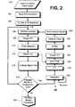
- Fig. 2 illustrating a block diagram of signal processing in accordance with a first embodiment of a fully digital dynamic leakage calibration and removal system in a LFM-CW automotive radar system
- the down-converted radar signal 200 from the second mixer 18.4 and a phase shifted version thereof are converted in step 202 by ADC's 26.1, 26.2 to form the in-phase (I) and quadrature-phase (Q) signals.
- step 204 the DC bias and I/Q imbalance is removed so as to provide the I and Q waveforms corresponding to the associated down-converted radar signal 200, as illustrated in Fig. 4.
- the down-converted radar signal comprises the sum of the leakage signal with the received radar return signal.
- the received radar return signal is Doppler shifted by moving targets.
- the leakage signal however has a constant frequency that is the same as the transmit frequency, as for the radar return from stationary targets, but generally with a much stronger magnitude than radar return signals.
- Pre-computed leakage signals for each beam location of the multi-beam radar system are initially stored with the program code in EPROM in the form of the associated I and Q waveforms - a separate leakage signal for each beam location.
- the leakage signals are inherently synchronized with the associated radar carrier and chirp signals because of the coherency resulting from direct digital synthesis thereof.
- the signal processor 30 subtracts the complex I/Q waveforms of the leakage signal from the incoming In-phase and Quadrature-phase sampled complex I/Q radar signal in step 206 and performs traditional LFM waveform processing, consisting of Fast Fourier Transform (FFT) in step 208 and Constant False Alarm Rate (CFAR) detection processing in step 210.
- FFT Fast Fourier Transform
- CFAR Constant False Alarm Rate
- the process of CFAR detection is known to those of ordinary skill in the art, for example, as described in "Radar CFAR Thresholding in Clutter and Multiple Target Situations" by Hermann Rholing in IEEE Transactions on Aerospace and Electronic Systems, Vol. AES-19, No. 4, July 1983, which is incorporated herein by reference.
- the output of the CFAR detector is a list of possible target reports 212 , which includes:
- the leakage signal is tested in step 214 by a leakage tester which is preset to know the possible range cell locations of the leakage signal, based on the fact that the leakage location is roughly constant, to within 1-2 range cells, for a specific radar hardware configuration.
- the tester analyzes both the amplitude and the modality of the leakage signal. For example, the amplitude of the leakage signal in range space (after FFT) is compared with a threshold of approximately 5 dB, wherein a rise greater than the threshold indicates an incorrect leakage signal.
- the modality of the leakage signal is tested using 3 rd order moments in FFT amplitude space. If the leakage signal being used is incorrect, the amplitude of the leakage will grow and the signal may also experience a drift in frequency causing it to move in range and now appear as two closely spaced peaks, rather than a single peak.
- a leakage tolerance flag is set. If this flag is set m-of-N times on the next N times the radar uses a particular beam, then in step 216 the system is flagged to begin a new beam calibration.
- the values of m and N are typically chosen to be 3-of-4. Alternatively, a calibration may be automatically rescheduled every 100 scans. The system uses the latest valid leakage signal for processing incoming radar signals.
- a running sum filter averages out any possible thermal Gaussian noise by computing the running sum for each step in the sequential frequency stepped LFM radar signal. This summation process continues at each beam location for M occurrences when the antenna is returned to the particular beam location, where values of M between 25 to 100, for example, provide excellent noise reduction.
- the running sum is performed independently on the I and Q channels of the complex data to preserve the phase of the resulting leakage signal.
- This running sum is performed at each time sample of the repetitive LFM waveform kernel (chirp) over the M-plurality of successive waveform cycles. For example, for time sample 1 in the incoming waveform, 25-100 instances of that value are summed together. This processing step then generates an associated averaged waveform that corresponds to the incoming data sequence for each LFM data collection interval.
- the averaged waveform is then filtered in steps 254, 256, and 258 to remove known targets while preserving the main leakage signal and any images of the leakage signal which may be present due to limited image rejection capabilities of the various mixers in the system.
- Such filtering may be achieved by first, in step 254, transforming the averaged waveform into range space using a FFT; then, in step 256, removing the associated targets with a notch filter; and finally, in step 258, transforming the filtered signal back to the time domain using an inverse FFT.
- the notch filter in step 256 utilizes the report list 212 from the CFAR detection step 210 to identify the targets for removal from the averaged waveform. Alternatively, this filtering process may be implemented in the time domain.
- targets appear as higher frequency signals in the LFM waveform than the leakage signal since they are farther in range than the leakage. If the targets were not removed from the averaged waveform as described hereinabove, then, if the system were stationary and there were other objects in the radar's field of view, these objects would be incorporated into a resulting corrupted leakage signal, and accordingly calibrated out by the system along with the leakage. However, when the system began moving again, the calibration using the corrupted leakage signal would then make a false target appear at that same location for all subsequent scans, because when the corrupted leakage signal is subtracted, the subtraction process effectively adds signal components into the incoming waveform where not otherwise present therein.
- the filtered signal is then, in step 260, scaled to be of unity amplitude to provide for easier scaling in the leakage subtraction logic step 206, wherein the stored leakage signal is scaled to match the peak value of the incoming I/Q signal before subtraction therefrom.
- variance waveforms of the I and Q channels are computed for use as a diagnostic measure and verify the quality of the leakage signal.
- the variance of the I and Q channels is checked in step 262 before storing, in step 264, the computed leakage signal from step 260 as the leakage reference signal, so as to prevent a very poor quality leakage reference signal from being generated if the system is experiencing radar front-end hardware problems. If the variance check fails, for example, as a result of the variance of any point in the variance waveforms being more than 5 times greater than an adjacent point, then the computed leakage signal from step 260 is discarded, and the leakage calibration process 250 is repeated. If after a second attempt the variance signal is still out of tolerance, a diagnostics flag is set and the system enters a self-test mode, for example, by switching the MBA to a non-radiative mode so that the radar system only measures internal leakage.
- step 262 If, in step 262, the variance of the leakage signal is within tolerance, then the calculated leakage signal is stored in step 264 as the leakage reference signal for subsequent use in removing leakage from incoming radar signals.
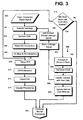
- a stored digital leakage signal from step 364 is converted to analog form by a DAC 34 in step 366.
- the system begins normal operation with a pre-computed leakage signal that is stored with the program code in EPROM, wherein a distinct leakage signal is associated with and stored for each beam location.
- the stored leakage signal from step 366 is subtracted in step 301 from the down-converted radar signal 300, and the resultant signal is scaled by a variable-gain amplifier in step 303, wherein the gain thereof is under control of the signal processor 30 as described hereinbelow.
- the scaled signal and a quadrature phase shifted version thereof are sampled and converted to the associated digital, complex I/Q signals in steps 302 and 304.
- the signal processor 30 performs traditional LFM waveform processing, consisting of Fast Fourier Transform (FFT) in step 308, Constant False Alarm Rate (CFAR) detection processing in step 310, and Doppler processing in step 314 across a set ofN complete LFM waveforms for each range cell that reported a detection.
- FFT Fast Fourier Transform
- CFAR Constant False Alarm Rate
- Doppler processing in step 314 across a set ofN complete LFM waveforms for each range cell that reported a detection.
- the output of the CFAR detector is a list of possible target reports 312, which includes:
- step 316 For every N th scan of incoming radar data, where, for example, N is approximately 100, in step 316, the leakage calibration process 350 is performed (in addition to normal radar signal processing) to track and update the leakage signal.
- M chirps comprising a complete radar dwell at a particular beam location are averaged to reduce thermal Gaussian noise, where, for example, M is between 8 and 16 chirps at each beam location (dwell) for adequate noise reduction and Doppler sensitivity and accuracy in the normal radar processing.
- the average is calculated independently on the I and Q channels of the complex data to preserve the phase of the leakage signal, so as to generate a leakage signal waveform with a length equal to the incoming chirp length, for example, 64-128 points.
- the average is calculated across the respective chirp waveforms, respective points with in each waveform averaged with one another so as to create an average waveform.
- the associated variance waveforms of the I and Q channels are also computed, from which the system, in step 354, performs diagnostics to verify the quality of the leakage signal by comparing the measured variances to the associated stored variances for the I and Q channels that are used in a Kalman Filter stage.
- This variance check guards against generating poor quality leakage reference signals, for example, as a result of front-end hardware problems in the radar system.
- a poor variance causes the system to discard the just computed leakage reference signal and to calculate another. If after a second attempt the variance signal is still out of tolerance a diagnostics flag is set and the system enters a self-test mode.
- This averaged I/Q waveform has the appearance of a sinewave as shown in Fig. 4. Drifts of the leakage signal tends to cause small perturbations in the associated waveform over time.
- the instant invention treats each point of this waveform independently and runs a Kalman filter over time on each point using the new incoming data to provide a correction to the existing data in step 356, after which the associated Kalman Gain matrices are updated in step 358.
- est_leak (i) is a 2 element vector, the first element of which is the In-phase contribution of the signal and the second of which is the Quadrature-phase contribution of the signal.
- This form takes advantage of the fact that the In-phase portion is proportional to cos(t) and the Quadrature-phase portion is proportional to the sin(t) which is simply the time derivative (or in this application, velocity).
- the system noise matrix models the random 'accelerations' (Quadrature derivative) that are driving the system to drift over time.
- the variances ⁇ I 2 and ⁇ Q 2 are the respective variances of the I and Q channels that are estimated when the system is developed and compared to the variances of the incoming data in step 354 to ensure performance.
- the second set of variances in the system noise matrix are determined by modeling the system drift characteristics during development, for example, by sampling the data at hourly intervals, where the indices 1 and 2 of the variances correspond to I and Q respectively. These elements of the system noise matrix can be also be adjusted to tune the system.
- the system begins with an estimate for these matrices and P est to initiate the processing. P est is estimated during system development based on what the desired Gain matrix characteristics should be.
- the Gain matrix changes with each iteration are illustrated in Fig. 5 , which plots the evolution of each term over time.
- the newly updated leakage signal from step 356 is then, in step 364 , stored in processor memory and subsequently used in place of the EPROM based leakage signal that was factory delivered with the automotive radar system.
- the EPROM is not overwritten, but is instead available to prevent the calibration from "wandering" too far from the factory programmed calibration.
- the system dynamic range is cost effectively improved by converting, in step 366, the stored digital leakage signal from step 364 to an analog signal by a Digital to Analog Converter 34 (DAC), which is then subtracted, in step 301, from the down-converted radar signal 300 .
- the resulting difference signal is amplified in step 303 by a variable gain amplifier 38 to take advantage of the Analog to Digital Converter's (ADC's) 26.1, 26.2 available dynamic range, so as to decrease the noise due to quantization error and increase the system dynamic range, the improvement bounded by the condition where quantization noise falls below the system noise floor.
- ADC's Analog to Digital Converter's
- Increasing the system dynamic range allows smaller targets to be detected by the system.
- the radar return is composed of 2 signal components, the leakage signal and target signal.
- P c must be set less than or equal to P x to avoid ADC overflow. If P c is set equal to P x , then the available SQNR for target detection is decreased by the Leakage-to-Target Ratio (LTR), which is equal to 10*log(P Leakage /P Target ), which, for example, is typically 40-80 dB.
- LTR Leakage-to-Target Ratio
- the leakage template - the digital form of the leakage calibration signal - power P LT is equal to the power P L of the leakage minus the quantization error of the DAC:
- Q N D A C A Leakage 2 3 2 ( m + 1 )
- P L T P L ⁇ Q N D A C were m is the number of bits in the DAC.
- G is set so that P Gain is equal to the P X of the ADC.
- the leakage calibration system is designed to track long term changes in the behavior of the leakage signal. For instance, the variation in temperature that would cause the system to drift out of tolerance can take on the order of a few hours to cause thermal heating sufficient enough to cause the radar assembly to thermally expand out of tolerance. The system, however, can also react on à more rapid basis if, for instance, a large quantity of mud were splashed onto the radar and it affected the characteristics of the radome.
- Short term effects such as unusual power surges that may cause the LFM waveform to be corrupted would not affect the leakage calculation since these are either of short duration, or if longer duration, would be flagged by the variance test on the leakage reference signal calculation and would flag the control processing task of the radar of a potential system failure that requires immediate service attention.
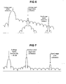
- the original uncompensated leakage signal is shown to dominate the target spectrum. Even medium sized targets are much harder to detect since their amplitude relative to the background is significantly reduced. Smaller targets are completely masked by the background of the leakage signal.
- the leakage is reduced significantly by the above described dynamic leakage calibration process, enabling the targets to be much easier to detect relative to the background clutter and noise.
Landscapes
- Engineering & Computer Science (AREA)
- Radar, Positioning & Navigation (AREA)
- Remote Sensing (AREA)
- Physics & Mathematics (AREA)
- General Physics & Mathematics (AREA)
- Computer Networks & Wireless Communication (AREA)
- Multimedia (AREA)
- Theoretical Computer Science (AREA)
- Electromagnetism (AREA)
- Radar Systems Or Details Thereof (AREA)
Claims (33)
- Ein Verfahren zum Entfernen von Streuverlusten in einem Dauerstrichradarsystem (10), das umfasst:a. Abziehen (206, 301) mindestens eines für ein Verlustsignal charakteristischen Signals von einem entsprechenden mindestens einen für ein herunterkonvertiertes Radarrücklaufsignal (200, 300) charakteristischen Signal, um ein resultierendes Signal zu bilden, wobei das mindestens eine für ein herunterkonvertiertes Radarrücklaufsignal (200, 300) charakteristische Signal und/oder das resultierende Signal eine sich wiederholenden Sequenz von Frequenzen umfasst; gekennzeichnet durchb. Auswerten (216, 316) eines Zustandes des resultierenden Signals; undc. Bestimmen aus diesem Zustand, ob Streuverlustkalibrierung (250, 350) durchgeführt werden soll oder nicht, wobei die Streuverlustkalibrierung (250, 350) umfasst:i) Erzeugen (252-260, 352) eines gemittelten Verlustsignals;ii) Berechnen (262, 354) mindestens einer Varianzwellenform, die dem gemittelten Verlustsignal zugeordnet ist;iii) Vergleichen (262, 354) mindestens eines Maßes der mindestens einen Varianzwellenform mit einem entsprechenden mindestens einen Schwellenwert; undiv) Speichern (264, 364) eines Signals in Antwort auf das gemittelte Verlustsignal, wobei der Schritt des Speicherns auf den Schritt des Vergleichens (262, 354) des mindestens einen Maßes der mindestens einen Varianzwellenform mit dem entsprechenden mindestens einen Schwellenwert reagiert.
- Ein Verfahren zum Entfernen von Streuverlusten in einem Dauerstrichradarsystem (10) wie in Anspruch 1 aufgeführt, wobeia. der Schritt des Abziehens (206, 301) des mindestens einen für ein Verlustsignal charakteristischen Signals von dem entsprechenden mindestens einen für das herunterkonvertierte Radarrücklaufsignal (200, 300) charakteristische Signal umfasst:i). Abtasten (202) der gleichphasigen (I) und quadratur-phasigen (Q) Komponenten eines herunterkonvertierten Radarrücklaufsignals (200), wobei jede Komponente eine zugeordnete Wellenform umfasst, die eine sich wiederholende Sequenz von Frequenzen umfasst; undii). Abziehen (206) der gleichphasigen (I) und quadratur-phasigen (Q) Komponenten eines gespeicherten Verlustsignals, um ein resultierendes Signal zu bilden;b. die Schritte des Auswertens (216, 316) des Zustandes des resultierenden Signals und des Bestimmens aus diesem Zustand, ob die Verlustkalibrierung (250, 350) durchgeführt werden soll oder nicht, umfassen:i) Vergleichen (214) mindestens eines ersten Maßes des resultierenden Signals mit einem entsprechenden mindestens einen ersten Schwellenwert; undii) Durchführen einer Verlustkalibrierung (250), wenn das mindestens eine erste Maß den entsprechenden mindestens einen Schwellenwert für m von N aufeinanderfolgenden Abtastwerten (216) des Radarrücklaufsignals (200) übersteigt;c. der Schritt des Erzeugens (250) des gemittelten Verlustsignals umfasst:i) Berechnen (252) eines laufenden Mittelwertes aufeinanderfolgender gleichphasiger (I) Wellenformen des herunterkonvertierten Radarrücklaufsignals (200) durch Mitteln (252) zugehöriger Elemente der sich wiederholenden Sequenz über aufeinanderfolgende sich wiederholende Sequenzen, um eine zugeordnete gemittelte Gleichphasenwellenform zu erzeugen; undii) Berechnen eines laufenden Mittelwertes aufeinanderfolgender quadratur-phasiger (Q) Wellenformen des herunterkonvertierten Radarrücklaufsignals (200) durch Mitteln (252) zugehöriger Elemente der sich wiederholenden Sequenz über aufeinanderfolgende sich wiederholende Sequenzen, um eine zugeordnete gemittelte Quadraturphasenwellenform zu erzeugen, wobei die Gleichphasenwellenform und die Quadraturphasenwellenform das gemittelte Verlustsignal darstellen;d. der Schritt des Vergleichens mindestens einen Maßes der mindestens einen Varianzwellenform mit einem entsprechenden mindestens einen Schwellenwert umfasst:Vergleichen (262) mindestens eines zweiten Maßes der mindestens einen Varianzwellenform mit einem entsprechenden mindestens einen zweiten Schwellenwert; unde. der Schritt des Speicherns des Signals in Antwort auf das gemittelte Verlustsignal umfasst:Speichern (264) des gemittelten Verlustsignals als das gespeicherte Verlustsignal, wenn das mindestens eine zweite Maß der mindestens einen Varianzwellenform geringer ist als der entsprechende mindestens eine zweite Schwellenwert.
- Ein Verfahren zum Entfernen von Streuverlusten in einem Dauerstrichradarsystem (10) wie in Anspruch 2 aufgeführt, wobei das gespeicherte Verlustsignal anfangs auf einen vorberechneten Wert gesetzt wird.
- Ein Verfahren zum Entfernen von Streuverlusten in einem Dauerstrichradarsystem (10) wie in Anspruch 2 aufgeführt, weiterhin umfassend den Schritt des Skalierens (260) des gespeicherten Verlustsignals in Antwort auf die Größe des herunterkonvertierten Radarrücklaufsignals (200).
- Ein Verfahren zum Entfernen von Streuverlusten in einem Dauerstrichradarsystem (10) wie in Anspruch 4 aufgeführt, wobei das gespeicherte Verlustsignal skaliert (260) wird, um die selbe Spitzengröße wie das herunterkonvertierte Radarrücklaufsignal (200) zu haben.
- Ein Verfahren zum Entfernen von Streuverlusten in einem Dauerstrichradarsystem (10) wie in Anspruch 2 aufgeführt, wobei das mindestens eine erste Maß die maximale Amplitude der Verlustkomponente des resultierenden Signals umfasst.
- Ein Verfahren zum Entfernen von Streuverlusten in einem Dauerstrichradarsystem (10) wie in Anspruch 6 aufgeführt, wobei das erste Maß innerhalb eines vorbestimmten Frequenzbereichs getestet wird (254), der der Verlustkomponente des resultierenden Signals entspricht.
- Ein Verfahren zum Entfernen von Streuverlusten in einem Dauerstrichradarsystem (10) wie in Anspruch 2 aufgeführt, wobei das mindestens eine erste Maß die Modalität der Verlustkomponente des resultierenden Signals umfasst.
- Ein Verfahren zum Entfernen von Streuverlusten in einem Dauerstrichradarsystem (10) wie in Anspruch 8 aufgeführt, wobei der mindestens eine erste Schwellenwert die Anzahl der nahe beieinanderliegenden Spitzenwerte in der Verlustkomponente des resultierenden Signals umfasst.
- Ein Verfahren zum Entfernen von Streuverlusten in einem Dauerstrichradarsystem (10) wie in Anspruch 8 aufgeführt, wobei das mindestens eine erste Maß das Moment dritter Ordnung in der Entfernungsdomäne der Verlustkomponente des resultierenden Signals umfasst.
- Ein Verfahren zum Entfernen von Streuverlusten in einem Dauerstrichradarsystem (10) wie in Anspruch 2 aufgeführt, weiterhin umfassend den Schritt des Skalierens (260) des gemittelten Verlustsignals bevor das gemittelte Verlustsignal gespeichert wird.
- Ein Verfahren zum Entfernen von Streuverlusten in einem Dauerstrichradarsystem (10) wie in Anspruch 10 aufgeführt, wobei das Dauerstrichradarsystem (10) schrittlinear frequenzmoduliert ist, weiterhin umfassend den Schritt des Bearbeitens (208, 210) des herunterkonvertierten Radarrücklaufsignals (200), um den Abstand zu null oder mehr Zielen zu messen, die durch das Radarrücklaufsignal (200) dargestellt werden.
- Ein Verfahren zum Entfernen von Streuverlusten in einem Dauerstrichradarsystem (10) wie in Anspruch 10 ausgeführt, wobei der Schritt des Bearbeitens (208, 210) des herunterkonvertierten Radarrücklaufsignals (200) die Schritte der Fast-Fourier-Transformation (208) und Constant False Alarm Rate-Feststellungsbearbeitung (210) umfasst.
- Ein Verfahren zum Entfernen von Streuverlusten in einem Dauerstrichradarsystem (10) wie in Anspruch 13 ausgeführt, wobei der Schritt der Constant False Alarm Rate-Feststellungsbearbeitung (210) mindestens ein Maß bereitstellt, das aus einer Gruppe ausgewählt wird, die aus dem Entfernungszellenort, der Radarstrahlzahl, der Amplitude des Radarrücklaufsignals (200) und der Amplitude des Hintergrunds des Radarrücklaufsignals (200) besteht.
- Ein Verfahren zum Entfernen von Streuverlusten in einem Dauerstrichradarsystem (10) wie in Anspruch 14 aufgeführt, weiterhin umfassend den Schritt des Entfernens von durch den Schritt der Constant False Alarm Rate-Feststellungsbearbeitung (210) entdeckten Zielen aus dem gemittelten Verlustsignal (212, 254-258) umfasst.
- Ein Verfahren zum Entfernen von Streuverlusten in einem Dauerstrichradarsystem (10) wie in Anspruch 15 aufgeführt, wobei der Schritt des Entfernens von Zielen die Schritte des Anwendens einer Fast-Fourier-Transformation (254) auf das gemittelte Verlustsignal, um ein Signal in der Frequenzdomäne zu bilden, Verwenden eines Sperrfilters (256) auf das Signal in der Frequenzdomäne in Antwort auf die durch den Constant False Alarm Rate-Feststellungsbearbeitungsschritt (210) entdeckten Ziele, um ein sperrgefiltertes Signal zu erzeugen, und des Anwendens einer inversen Fast-Fourier-Transformation (258) auf das sperrgefilterte Signal umfasst, um einen Ersatz für das gemittelte Verlustsignal zu bilden.
- Ein Verfahren zum Entfernen von Streuverlusten in einem Dauerstrichradarsystem (10) wie in Anspruch 14 aufgeführt, wobei der Schritt des Durchführens einer Verlustkalibrierung (250) durchgeführt wird, wenn keine Ziele in dem Constant False Alarm Rate-Feststellungsbearbeitungsschritt (210) entdeckt werden.
- Ein Verfahren zum Entfernen von Streuverlusten in einem Dauerstrichradarsystem (10) wie in Anspruch 2 aufgeführt, wobei das Dauerstrichradarsystem (10) eine Mehrstrahlenanordnung (12: 12.1, 12.2, 12.3) umfasst, das gespeicherte Verlustsignal für jeden Strahlort (12.1, 12.2, 12.3) in der Mehrstrahlenanordnung (12: 12.1, 12.2, 12.3) ausgeprägt ist und der Schritt des Durchführens einer Verlustkalibrierung (250) für jeden Strahlort (12.1, 12.2, 12.3) in der Mehrstrahlenanordnung (12: 12.1, 12.2, 12.3) separat durchgeführt wird.
- Ein Verfahren zum Entfernen von Streuverlusten in einem Dauerstrichradarsystem (10) wie in Anspruch 1 ausgeführt, wobeia. der Schritt des Abziehens mindestens eines für ein Verlustsignal charakteristischen Signals von dem entsprechenden mindestens einen für ein herunterkonvertiertes Radarrücklaufsignal (300) charakteristischen Signal umfasst:Abziehen (301) eines gespeicherten Verlustsignals von einem herunterkonvertierten Radarrücklaufsignal (300), um ein resultierendes Signal zu bilden, wobei das herunterkonvertierte Radarrücklaufsignal (300) eine sich wiederholende Sequenz von Frequenzen umfasst;b. die Schritte des Evaluierens des Zustandes des resultierenden Signals und Bestimmens aus diesem Zustand, ob eine Verlustkalibrierung durchgeführt wird oder nicht, umfassen:Durchführen einer Verlustkalibrierung (350) bei jedem N-ten Auftreten (316) der sich wiederholenden Sequenz von Frequenzen;c. der Schritt des Erzeugens des gemittelten Verlustsignals umfasst:Berechnen eines Durchschnitts von aufeinanderfolgenden resultierenden Signalen durch Mitteln (352) zugehöriger Elemente der sich wiederholenden Sequenz über aufeinanderfolgende sich wiederholende Sequenzen, um das gemittelte Verlustsignal zu erzeugen; undd. der Schritt des Speicherns des Signals in Antwort auf das gemittelte Verlustsignal umfasst:i) Kombinieren des gespeicherten Verlustsignals mit dem gemittelten Verlustsignal in Übereinstimmung mit einem Kalman-Filter (356), um ein aktualisiertes Verlustsignal zu bilden, wenn mindestens ein Maß der mindestens einen Varianzwellenform geringer ist als der entsprechende mindestens eine Schwellenwert (354); undii) Speichern (364) des aktualisierten Verlustsignals als das gespeicherte Verlustsignal.
- Ein Verfahren zum Entfernen von Streuverlusten in einem Dauerstrichradarsystem (10) wie in Anspruch 19 aufgeführt, wobei der Kalman-Filter (356) auf die Rauschstatistiken des Radarsystems (10) anspricht.
- Ein Verfahren zum Entfernen von Streuverlusten in einem Dauerstrichradarsystem (10) wie in Anspruch 19 aufgeführt, wobei der Kalman-Filter (356) auf die Verluststabilität des Radarsystems (10) anspricht.
- Ein Verfahren zum Entfernen von Streuverlusten in einem Dauerstrichradarsystem (10) wie in Anspruch 19 aufgeführt, wobei der Kalman-Filter (356) auf die Stabilität des Radarsystems (10) anspricht.
- Ein Verfahren zum Entfernen von Streuverlusten in einem Dauerstrichradarsystem (10) wie in Anspruch 19 aufgeführt, weiterhin umfassend den Schritt des Aktualisierens (358) mindestens einer Gain-Matrix des Kalman-Filters (356).
- Ein Verfahren zum Entfernen von Streuverlusten in einem Dauerstrichradarsystem (10) wie in Anspruch 1 aufgeführt, wobeia. der Schritt des Abziehens mindestens eines für ein Verlustsignal charakteristischen Signals von dem entsprechenden mindestens einen für ein herunterkonvertiertes Radarrücklaufsignal (300) charakteristischen Signal umfasst:i). Konvertieren (366) eines gespeicherten Verlustsignals von einer digitalen in eine analoge Form, um ein analoges Verlustsignal zu bilden; undii). Abziehen (301) des analogen Verlustsignals von einem herunterkonvertierten Radarrücklaufsignal (300), um ein resultierendes Signal zu bilden;b. die Schritte des Auswertens des Zustandes des resultierenden Signals und des Bestimmens aus diesem Zustand, ob die Verlustkalibrierung durchgeführt werden soll oder nicht, umfassen:i). Abtasten (302) der gleichphasigen (I) und quadratur-phasigen (Q) Komponenten des resultierenden Signals, wobei jede Komponente eine zugeordnete Wellenform umfasst, die eine sich wiederholende Sequenz von Frequenzen umfasst; undii). Durchführen einer Verlustkalibrierung bei jedem N-ten Auftreten (316) der sich wiederholenden Sequenz von Frequenzen;c. der Schritt des Erzeugens des gemittelten Verlustsignals umfasst:i) Berechnen eines Durchschnitts von aufeinanderfolgenden gleichphasigen (I) Wellenformen des herunterkonvertierten Radarrücklaufsignals (300) durch Mitteln (352) zugehöriger Elemente der sich wiederholenden Sequenz über aufeinanderfolgende sich wiederholende Sequenzen, um eine zugeordnete gemittelte Gleichphasenwellenform zu erzeugen;ii) Berechnen eines Durchschnitts aufeinanderfolgender quadratur-phasigen (Q) Wellenformen des herunterkonvertierten Radarrücklaufsignals (300) durch Mitteln (352) zugehöriger Elemente der sich wiederholenden Sequenz über aufeinanderfolgende sich wiederholende Sequenzen, um eine zugeordnete gemittelte Quadraturphasenwellenform zu erzeugen, wobei die Gleichphasenwellenform und die Quadraturphasenwellenform das gemittelte Verlustsignal darstellen; undd. der Schritt des Speicherns des Signals in Antwort auf das gemittelte Verlustsignal umfasst:Ersetzen (356, 364) des gespeicherten Verlustsignals mit einem Signal aus dem gemittelten Verlustsignal, wenn das mindestens eine Maß der mindestens einen Varianzwellenform geringer ist als der entsprechende mindestens eine Schwellenwert.
- Ein Verfahren zum Entfernen von Streuverlusten in einem Dauerstrichradarsystem (10) wie in Anspruch 24 aufgeführt, weiterhin umfassend den Schritt des Skalierens (303) des resultierenden Signals.
- Ein Verfahren zum Entfernen von Streuverlusten in einem Dauerstrichradarsystem (10) wie in Anspruch 25 aufgeführt, wobei der Schritt des Abtastens der gleichphasigen (I) und quadratur-phasigen (Q) Komponenten des resultierenden Signals den Schritt des Konvertierens (302) des resultierenden Signals von einer analogen in eine digitale Form mit mindestens einem Analog-Digital-Konverter (26.1, 26.2) umfasst, und der Schritt des Skalierens (303) des resultierenden Signals auf den dynamischen Bereich des mindestens einen Analog-Digital-Konverters (26.1, 26.2) anspricht.
- Ein Verfahren zum Entfernen von Streuverlusten in einem Dauerstrichradarsystem (10) wie in Anspruch 24 aufgeführt, wobei das Dauerstrichradarsystem (10) schrittlinear frequenzmoduliert ist, weiterhin umfassend den Schritt des Bearbeitens des herunterkonvertierten Radarrücklaufsignals (300), um die Entfernung zu null oder mehr Zielen zu messen (308, 310), die durch das Radarrücklaufsignal (300) dargestellt werden.
- Ein Verfahren zum Entfernen von Streuverlusten in einem Dauerstrichradarsystem (10) wie in Anspruch 27 aufgeführt, wobei der Schritt des Bearbeitens des herunterkonvertierten Radarrücklaufsignals (300) die Schritte einer Fast-Fourier-Transformation (308) und einer Constant False Alarm Rate-Feststellungsbearbeitung (310) umfasst, und der Schritt der Constant False Alarm Rate-Feststellungsbearbeitung (310) mindestens ein Maß bereitstellt, das aus der Gruppe gewählt wird, die den Entfernungszellenort, die Radarstrahlzahl, die Amplitude des Radarrücklaufsignals (300) und die Amplitude des Hintergrunds des Radarrücklaufsignals (300) umfasst.
- Ein Verfahren zum Entfernen von Streuverlusten in einem Dauerstrichradarsystem (10) wie in Anspruch 24 aufgeführt, wobei N zwischen 10 und 1000 ist.
- Ein Verfahren zum Entfernen von Streuverlusten in einem Dauerstrichradarsystem (10) wie in Anspruch 24 aufgeführt, wobei der Durchschnitt auf 5 bis 50 Abtastungen basiert.
- Ein Verfahren zum Entfernen von Streuverlusten in einem Dauerstrichradarsystem (10) wie in Anspruch 24 aufgeführt, wobei das Dauerstrichradarsystem (10) eine Mehrstrahlenanordnung (12: 12.1, 12.2, 12.3) umfasst, das gespeicherte Verlustsignal für jeden Strahlort (12.1, 12.2, 12.3) in der Mehrstrahlenanordnung (12: 12.1, 12.2, 12.3) ausgeprägt ist und der Schritt des Durchführens einer Verlustkalibrierung (250) separat für jeden Strahlort (12.1, 12.2, 12.3) in der Mehrstrahlenanordnung (12: 12.1, 12.2, 12.3) durchgeführt wird.
- Ein System zum Entfernen von Streuverlusten in einem Dauerstrichradarsystem (10), umfassend:a. einen Differenzverstärker (36), wobei der Eingang des Differenzverstärkers (36) wirkend mit einem herunterkonvertierten Radarsignal (300) innerhalb des Dauerstrichradarsystems (10) gekoppelt ist;b. einen Signalprozessor (30);c. einen mit dem Signalprozessor (30) zum Speichern eines Verlustsignals wirkend verbundenen Speicher;d. einen mit dem Signalprozessor (30) wirkend verbundenen Digital-Analog-Konverter (34);e. einen verstärkungsgesteuerten Verstärker (38), wobei der Eingang des verstärkungsgesteuerten Verstärkers wirkend mit dem Ausgang des Differenzverstärkers (36) verbunden ist und die Verstärkungssteuerung des verstärkungsgesteuerten Verstärkers (38) wirkend mit dem Signalprozessor (30) verbunden ist;f. einen ersten Analog-Digital-Konverter (26.1), wobei der Eingang des ersten Analog-Digital-Konverters (26.1) wirkend mit dem Ausgang des verstärkungsgesteuerten Verstärkers (38) verbunden ist, der Ausgang des ersten Analog-Digital-Konverters (26.1) wirkend mit dem Signalprozessor (30) verbunden ist, wobei der erste Analog-Digital-Konverter (26.1) dem Signalprozessor (30) ein Gleichphasensignal (I) bereitstellt;g. einen Quadraturphasenschieber (28), wobei der Eingang des Quadraturphasenschiebers (28) wirkend mit dem Ausgang des verstärkungsgesteuerten Verstärkers (38) verbunden ist; undh. einen zweiten Analog-Digital-Konverter (26.2), wobei der Eingang des zweiten Analog-Digital-Konverters (26.2) wirkend mit dem Ausgang des Quadraturphasenschiebers (28) verbunden ist, der Ausgang des zweiten Analog-Digital-Konverters (26.2) wirkend mit dem Signalprozessor (30) verbunden ist, wobei der zweite Analog-Digital-Konverter (26.2) dem Signalprozessor (30) ein Quadraturphasensignal (Q) bereitstellt, der Signalprozessor (30) ein Verlustkalibrierungssignal aus den Gleichphasen- (I) und Quadraturphasen-(Q)-Signalen berechnet, der Signalprozessor (30) das Verlustkalibrierungssignal an den Digital-Analog-Konverter (34) ausgibt, der Differenzverstärker (36) das Signal an dem Ausgang des Digital-Analog-Konverters (34) von dem herunterkonvertierten Radarsignal (300) abzieht, das Verlustkalibrierungssignal aus mindestens einem Durchschnitt des Gleichphasensignals (I) und des Quadraturphasensignals (Q) berechnet (352) wird, und das Verlustkalibrierungssignal auf mindestens eine dem Verlustkalibrierungssignal zugeordnete Varianzwellenform anspricht (354, 356).
- Ein System zum Entfernen von Streuverlusten in einem Dauerstrichradarsystem (10) wie in Anspruch 32 aufgeführt, wobei die Verstärkung des verstärkungsgesteuerten Verstärkers (38) auf den dynamischen Bereich der ersten (26.1) und zweiten (26.2) Analog-Digital-Konverter anspricht.
Applications Claiming Priority (7)
| Application Number | Priority Date | Filing Date | Title |
|---|---|---|---|
| US173322 | 1993-12-23 | ||
| US6602597P | 1997-10-16 | 1997-10-16 | |
| US66025P | 1997-10-16 | ||
| US7196498P | 1998-01-20 | 1998-01-20 | |
| US71964P | 1998-01-20 | ||
| US09/173,322 US5969667A (en) | 1997-10-16 | 1998-10-15 | Radar system |
| PCT/US1998/021908 WO1999019744A1 (en) | 1997-10-16 | 1998-10-16 | Radar system |
Publications (3)
| Publication Number | Publication Date |
|---|---|
| EP0953155A1 EP0953155A1 (de) | 1999-11-03 |
| EP0953155A4 EP0953155A4 (de) | 2000-05-31 |
| EP0953155B1 true EP0953155B1 (de) | 2006-05-31 |
Family
ID=27370905
Family Applications (1)
| Application Number | Title | Priority Date | Filing Date |
|---|---|---|---|
| EP98957329A Expired - Lifetime EP0953155B1 (de) | 1997-10-16 | 1998-10-16 | Radarsystem |
Country Status (5)
| Country | Link |
|---|---|
| EP (1) | EP0953155B1 (de) |
| KR (1) | KR20000069480A (de) |
| CA (1) | CA2271154A1 (de) |
| DE (1) | DE69834710T2 (de) |
| WO (1) | WO1999019744A1 (de) |
Cited By (1)
| Publication number | Priority date | Publication date | Assignee | Title |
|---|---|---|---|---|
| RU2510040C2 (ru) * | 2012-06-19 | 2014-03-20 | Федеральное бюджетное образовательное учреждение высшего профессионального образования "Морской государственный университет имени адмирала Г.И. Невельского" | Устройство для определения состояния морской поверхности |
Families Citing this family (20)
| Publication number | Priority date | Publication date | Assignee | Title |
|---|---|---|---|---|
| AU5082300A (en) * | 1999-06-25 | 2001-01-31 | Powell, Stephen, David | Chirp waveform decoding system |
| JP2003507716A (ja) * | 1999-08-12 | 2003-02-25 | オートモーティブ システムズ ラボラトリー インコーポレーテッド | ニューラルネットワークレーダプロセッサ |
| US7161530B2 (en) * | 2005-02-22 | 2007-01-09 | The United States Of America As Represented By The Secretary Of The Army | System and method for radar calibration using antenna leakage |
| IL172864A0 (en) * | 2005-12-28 | 2007-02-11 | Camero Tech Ltd | Automatic delay calibration and tracking for ultrawideband antenna array |
| KR100749336B1 (ko) | 2006-04-04 | 2007-08-14 | 곽영길 | 항공탑재 레이다 이동 클러터 도플러 스펙트럼 보상방법 |
| DE102008050117A1 (de) * | 2008-10-06 | 2010-04-08 | Endress + Hauser Gmbh + Co. Kg | Kalibration einer Radareinheit mit gerätespezifischen Korrekturkurven |
| EP2439552A1 (de) * | 2010-10-06 | 2012-04-11 | Astrium Limited | Signalverarbeitung in einem Radarsystem zur Unterdrückung von Tx-Rx-Übersprechen |
| US9507013B2 (en) | 2013-06-20 | 2016-11-29 | Infineon Technologies Ag | Method, device and system for processing radar signals |
| JP6176079B2 (ja) | 2013-11-26 | 2017-08-09 | 株式会社デンソー | レーダ装置 |
| US9684070B2 (en) | 2013-12-20 | 2017-06-20 | Delta Mobile Systems, Inc | Radar apparatus with quiet switch calibration and associated methods |
| US9448301B2 (en) | 2013-12-20 | 2016-09-20 | Delta Mobile Systems, Inc. | Calibrated radar apparatus and associated methods |
| EP3244229A1 (de) * | 2016-05-13 | 2017-11-15 | Autoliv Development AB | Zur verringerung von interferenzen angeordnetes fahrzeugradarsystem |
| DE102017216867A1 (de) * | 2017-09-25 | 2019-03-28 | Robert Bosch Gmbh | Verfahren und Radarsensor zur Reduktion des Einflusses von Störungen bei der Auswertung mindestens eines Empfangssignals |
| JP7203817B2 (ja) * | 2018-03-13 | 2023-01-13 | 古河電気工業株式会社 | レーダ装置およびレーダ装置の対象物検出方法 |
| KR102090880B1 (ko) * | 2018-10-11 | 2020-03-18 | 한국과학기술원 | Fmcw 레이더에서의 누설 신호 감쇄 방법 및 그 레이더 시스템 |
| US11402464B2 (en) | 2019-02-25 | 2022-08-02 | Samsung Electronics Co., Ltd. | Radar leakage measurement update |
| US11402465B2 (en) * | 2019-04-05 | 2022-08-02 | Samsung Electronics Co., Ltd. | Radar leakage cancelation based on spatiotemporal relationship of transmit and receive antenna pairs |
| CN111596269B (zh) * | 2020-05-25 | 2022-04-19 | 中国人民解放军海军航空大学 | 一种雷达复合探测目标能力的检测方法 |
| KR102709263B1 (ko) * | 2020-10-21 | 2024-09-24 | (주)에이유 | CFAR (constant false alarm rate) 알고리즘 성능 향상을 위한 신호 전처리 기법 |
| CN112379336A (zh) * | 2020-11-06 | 2021-02-19 | 西安乾景防务技术有限公司 | 雷达信号检测方法、装置、设备和存储介质 |
Family Cites Families (9)
| Publication number | Priority date | Publication date | Assignee | Title |
|---|---|---|---|---|
| US3256520A (en) * | 1963-01-04 | 1966-06-14 | Sanders Associates Inc | Feed through cancellation for an fm radar |
| US3703004A (en) * | 1971-07-01 | 1972-11-14 | Singer Co | Leakage filter for frequency modulated continuous wave doppler radar system |
| US4044357A (en) * | 1975-12-04 | 1977-08-23 | Westinghouse Electric Corporation | FM/CW radar including a novel receiver protector of general utility |
| US4725842A (en) * | 1982-09-27 | 1988-02-16 | Teledyne Industries, Inc. | Isolation apparatus for a continuous-wave radar system |
| FR2603385B1 (fr) * | 1986-08-27 | 1988-11-10 | Trt Telecom Radio Electr | Radar a onde continue modulee en frequence pour mesure de distance |
| GB2226204A (en) * | 1988-12-07 | 1990-06-20 | Philips Electronic Associated | Continuously transmitting and receiving radar |
| US5191337A (en) * | 1992-02-25 | 1993-03-02 | Hughes Aircraft Company | Ranging, detection and resolving in a multislope frequency modulated waveform radar system |
| CA2127160A1 (en) * | 1994-06-30 | 1995-12-31 | Shahrokh Ehsani-Nategh | System and method for radar-vision for vehicles in traffic |
| US5861837A (en) * | 1997-03-19 | 1999-01-19 | Northrop Grumman Corporation | Poly-frequency CW doppler radar system with leakage cancellation and method |
-
1998
- 1998-10-16 CA CA002271154A patent/CA2271154A1/en not_active Abandoned
- 1998-10-16 DE DE69834710T patent/DE69834710T2/de not_active Expired - Fee Related
- 1998-10-16 EP EP98957329A patent/EP0953155B1/de not_active Expired - Lifetime
- 1998-10-16 WO PCT/US1998/021908 patent/WO1999019744A1/en not_active Ceased
- 1998-10-16 KR KR1019997005324A patent/KR20000069480A/ko not_active Withdrawn
Cited By (1)
| Publication number | Priority date | Publication date | Assignee | Title |
|---|---|---|---|---|
| RU2510040C2 (ru) * | 2012-06-19 | 2014-03-20 | Федеральное бюджетное образовательное учреждение высшего профессионального образования "Морской государственный университет имени адмирала Г.И. Невельского" | Устройство для определения состояния морской поверхности |
Also Published As
| Publication number | Publication date |
|---|---|
| DE69834710D1 (de) | 2006-07-06 |
| DE69834710T2 (de) | 2007-05-10 |
| KR20000069480A (ko) | 2000-11-25 |
| WO1999019744A8 (en) | 1999-09-02 |
| EP0953155A1 (de) | 1999-11-03 |
| CA2271154A1 (en) | 1999-04-22 |
| WO1999019744A1 (en) | 1999-04-22 |
| EP0953155A4 (de) | 2000-05-31 |
Similar Documents
| Publication | Publication Date | Title |
|---|---|---|
| US5969667A (en) | Radar system | |
| EP0953155B1 (de) | Radarsystem | |
| US7683827B2 (en) | System and method for reducing the effect of a radar interference signal | |
| EP1672379B1 (de) | System und Verfahren zur Verminderung eines Radarstörsignals | |
| US6664920B1 (en) | Near-range microwave detection for frequency-modulation continuous-wave and stepped frequency radar systems | |
| EP3923023A2 (de) | Verarbeitung von radarsignalen | |
| JP2020067455A (ja) | 妨害信号抑圧を行うfmcwレーダー | |
| EP1651978B1 (de) | Verbesserter prozess für phasenabgeleitete entfernungsmessungen | |
| EP3244229A1 (de) | Zur verringerung von interferenzen angeordnetes fahrzeugradarsystem | |
| EP3324205B1 (de) | Dezentralisiertes radarsystem | |
| US6833808B2 (en) | Signal processing | |
| JP4668198B2 (ja) | レーダ装置 | |
| GB2283631A (en) | Radar | |
| JP3929080B2 (ja) | レーダシステム | |
| US12461195B2 (en) | Near-range interference mitigation for automotive radar system | |
| US11681039B2 (en) | Failure determination apparatus and method of vehicle radar apparatus, and vehicle radar apparatus with the same | |
| Dikshtein et al. | Automotive radar maximum unambiguous velocity extension via high-order phase components | |
| US6369748B1 (en) | Radar system mounted on vehicle | |
| EP4275070B1 (de) | Radarvorrichtung für kraftfahrzeuge und verfahren zur bestimmung einer eindeutigen radialgeschwindigkeit | |
| US20250116754A1 (en) | Transmit power control for automotive radar sensing | |
| Wei et al. | Design of Frequency-PRT Coupled Agile Waveform and Low-Complexity Signal Processing | |
| CN118519140A (zh) | 雷达系统和用于运行雷达系统的方法 | |
| Raffaeli et al. | Simulating and testing of signal processing methods for frequency stepped chirp radar |
Legal Events
| Date | Code | Title | Description |
|---|---|---|---|
| PUAI | Public reference made under article 153(3) epc to a published international application that has entered the european phase |
Free format text: ORIGINAL CODE: 0009012 |
|
| 17P | Request for examination filed |
Effective date: 19990716 |
|
| AK | Designated contracting states |
Kind code of ref document: A1 Designated state(s): DE FR GB |
|
| A4 | Supplementary search report drawn up and despatched |
Effective date: 20000417 |
|
| AK | Designated contracting states |
Kind code of ref document: A4 Designated state(s): DE FR GB |
|
| RIC1 | Information provided on ipc code assigned before grant |
Free format text: 7G 01S 13/00 A, 7G 01S 7/40 B, 7G 01S 7/03 B |
|
| 17Q | First examination report despatched |
Effective date: 20040809 |
|
| GRAP | Despatch of communication of intention to grant a patent |
Free format text: ORIGINAL CODE: EPIDOSNIGR1 |
|
| GRAS | Grant fee paid |
Free format text: ORIGINAL CODE: EPIDOSNIGR3 |
|
| GRAA | (expected) grant |
Free format text: ORIGINAL CODE: 0009210 |
|
| AK | Designated contracting states |
Kind code of ref document: B1 Designated state(s): DE FR GB |
|
| REG | Reference to a national code |
Ref country code: GB Ref legal event code: FG4D |
|
| REF | Corresponds to: |
Ref document number: 69834710 Country of ref document: DE Date of ref document: 20060706 Kind code of ref document: P |
|
| PLBE | No opposition filed within time limit |
Free format text: ORIGINAL CODE: 0009261 |
|
| STAA | Information on the status of an ep patent application or granted ep patent |
Free format text: STATUS: NO OPPOSITION FILED WITHIN TIME LIMIT |
|
| EN | Fr: translation not filed | ||
| 26N | No opposition filed |
Effective date: 20070301 |
|
| GBPC | Gb: european patent ceased through non-payment of renewal fee |
Effective date: 20061016 |
|
| PG25 | Lapsed in a contracting state [announced via postgrant information from national office to epo] |
Ref country code: GB Free format text: LAPSE BECAUSE OF NON-PAYMENT OF DUE FEES Effective date: 20061016 |
|
| PGFP | Annual fee paid to national office [announced via postgrant information from national office to epo] |
Ref country code: DE Payment date: 20071025 Year of fee payment: 10 |
|
| PG25 | Lapsed in a contracting state [announced via postgrant information from national office to epo] |
Ref country code: FR Free format text: LAPSE BECAUSE OF FAILURE TO SUBMIT A TRANSLATION OF THE DESCRIPTION OR TO PAY THE FEE WITHIN THE PRESCRIBED TIME-LIMIT Effective date: 20070309 |
|
| PG25 | Lapsed in a contracting state [announced via postgrant information from national office to epo] |
Ref country code: FR Free format text: LAPSE BECAUSE OF FAILURE TO SUBMIT A TRANSLATION OF THE DESCRIPTION OR TO PAY THE FEE WITHIN THE PRESCRIBED TIME-LIMIT Effective date: 20060531 |
|
| PG25 | Lapsed in a contracting state [announced via postgrant information from national office to epo] |
Ref country code: DE Free format text: LAPSE BECAUSE OF NON-PAYMENT OF DUE FEES Effective date: 20090501 |