EP0953380A2 - Procédé et dispositif pour racler les cristaux d'un tambour de centrifugation - Google Patents
Procédé et dispositif pour racler les cristaux d'un tambour de centrifugation Download PDFInfo
- Publication number
- EP0953380A2 EP0953380A2 EP99102995A EP99102995A EP0953380A2 EP 0953380 A2 EP0953380 A2 EP 0953380A2 EP 99102995 A EP99102995 A EP 99102995A EP 99102995 A EP99102995 A EP 99102995A EP 0953380 A2 EP0953380 A2 EP 0953380A2
- Authority
- EP
- European Patent Office
- Prior art keywords
- drum
- peeling knife
- product
- peeling
- centrifuge
- Prior art date
- Legal status (The legal status is an assumption and is not a legal conclusion. Google has not performed a legal analysis and makes no representation as to the accuracy of the status listed.)
- Granted
Links
Images

Classifications
-
- B—PERFORMING OPERATIONS; TRANSPORTING
- B04—CENTRIFUGAL APPARATUS OR MACHINES FOR CARRYING-OUT PHYSICAL OR CHEMICAL PROCESSES
- B04B—CENTRIFUGES
- B04B11/00—Feeding, charging, or discharging bowls
- B04B11/08—Skimmers or scrapers for discharging ; Regulating thereof
Definitions
- the invention relates to a method for clearing the product from the centrifuge drum of a discontinuous centrifuge, whereby a peeling knife is pivoted into the flung off product layer and here with one against the direction of drum rotation the cutting edge peels off the product.
- the invention further relates to a device for performing of the method, with a attached to a clearing bar and through this or around this swiveling paring knife, which in its pivoted position the product layer with one of the Drum direction of rotation against the cutting edge.
- the clearing device from a pivotable about a vertical clearing bar Ploughshare on which a peeling knife is spring-mounted rotatably.
- the paring knife which extends only over a short height section the centrifuge drum extends against the direction of rotation the centrifuge drum into the product layer, e.g. B. sugar layer pressed in until it touches the working sieve.
- the peeling knife is then moved axially from its uppermost position moved towards the bottom of the drum and is then again move axially upwards before it goes into its Rest position is pivoted out.
- the invention has for its object the product discharge, the discharge time and the remaining product in the centrifuge bowl to optimize.
- this is Object achieved in that the peeling knife after its pivoting over almost the entire drum height of product contact the product over the entire drum height at the same time of the product layer rotating at the clearing speed peels off in layers and again when the drum screen is reached is swung out.
- the above object is achieved in that the cutting edge almost over when the peeling knife is swung in the entire drum height extends.
- This axial distance can be about Be 200 mm so that the peeling knife is in its idle state at a sufficient distance from the internals and the drum edge located.
- the efficiency of the product discharge is thereby according to the invention increases that the pivoting of the peeling knife in the direction of rotation the centrifuge drum and its swiveling against this direction of rotation he follows. By swiveling against the direction of rotation The remaining product on the lower edge of the peeling knife becomes the drum spent on product discharge.
- the Swinging in of the peeling knife is stopped immediately before the peeling knife touches the drum sieve.
- the peeling knife can be controlled pneumatically via electropneumatic Valves.
- Peeling knife is flatly concave on its front.
- the cutting edge of the peeling knife with the Drum screen or drum shell an angle of 80 ° to a little less than 90 °.
- the clearing bar is designed as a tube into which a nozzle assembly or individual nozzles are integrated for a deck or wash water task. Thereby can be a complete assembly from the product room Eliminate centrifuge.
- the schematic representations show a centrifuge drum 1, the drum casing with holes 2 on its inner wall by a not shown Working strainer is covered.
- the drum base 3 has a central one Product outlet opening on by a not shown Locking hood is lockable.
- the direction of rotation of the Centrifuge drum 1 is indicated by an arrow 5.
- An eccentric protrudes perpendicularly into the centrifuge drum 1 from above fixedly arranged clearing device from which only an axially parallel clearing bar 6 and a attached peeling knife 7 are shown.
- the peeling knife 7 can be in the direction swivel onto the drum jacket 2.
- Figure 3 shows the clearing device in the lowered position, in the peeling knife, which extends over the full drum height h 7 is lowered to the drum base 3. Also show Figures 3 and 4, the peeling knife 7 in its pivoted Position in which there is a Sugar layer 9 is present.
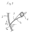
- Figure 5 shows the peeling knife 7 in its pivoted position after the peeling process, in which the Cut 7a of the peeling knife 7 immediately before that drawn working sieve of the drum shell 2 is, however without making a metallic contact with this working sieve.
- the cutting edge or cutting edge 7a closes with the Drum screen or drum shell 3 an angle ⁇ , the can be between 80 ° and a little less than 90 °.
- Figure 5 leaves also recognize that the peeling knife seen in horizontal section 7 is formed flat concave on its front side 7b.
- the magma fed into the centrifuge drum 1 is from the centrifugal drum 1 driven at high speed, the mother syrup adhering to the crystals through the Working sieve enters and out of the holes in the drum casing 3 the centrifuge housing, not shown, expires. Subsequently the crystals with a pure liquid washed. Those remaining in the drum after the separation process Crystals form a sugar layer 9 on the working sieve is peeled off from the clearing device. The peeled off Sugar crystals are subordinated after opening the cap Transport units fed.
- Figure 1 shows the clearing device in the raised state, in the lower end of the pivoted peeling knife 7 from the drum base 3 has an axial distance a, which is about 200 mm can be.
- the peeling knife 7 becomes from this idle state already during braking of the centrifuge drum 1 from it Spin speed to the clearing speed axially in the direction of Arrow 10 lowered until the lower end of the peeling knife 7 is immediately above the drum base 3 (see Figure 3). After It will reach the lower position and the clearing speed Swinging the peeling knife 7 in the direction of arrow 8 initiated.
- Figure 4 shows that the pivoting process of the peeling knife 7 in the direction of rotation 5 of the centrifuge drum 1 takes place.
- the peeling the sugar crystals then occur simultaneously over the entire Drum height h with continuous infeed of the peeling knife 7 in the radial direction to the outside.
- the one in front of the peeling knife 7 Line 11 drawn in dashed lines indicates the product flow the crystals peeled from the sugar layer 9 by the peeling knife 7 on.
- the peeling knife 7 has its shown in FIG When the end position is reached, the peeling knife remains for a few seconds in this end position before it returns to its position shown in FIGS and 2 shown starting position is pivoted out.
Landscapes
- Centrifugal Separators (AREA)
Applications Claiming Priority (2)
| Application Number | Priority Date | Filing Date | Title |
|---|---|---|---|
| DE19819065A DE19819065C1 (de) | 1998-04-29 | 1998-04-29 | Verfahren und Vorrichtung zum Ausräumen des Produktes aus einer Zentrifugentrommel |
| DE19819065 | 1998-04-29 |
Publications (3)
| Publication Number | Publication Date |
|---|---|
| EP0953380A2 true EP0953380A2 (fr) | 1999-11-03 |
| EP0953380A3 EP0953380A3 (fr) | 2000-06-07 |
| EP0953380B1 EP0953380B1 (fr) | 2002-08-21 |
Family
ID=7866108
Family Applications (1)
| Application Number | Title | Priority Date | Filing Date |
|---|---|---|---|
| EP99102995A Expired - Lifetime EP0953380B1 (fr) | 1998-04-29 | 1999-02-16 | Procédé et dispositif pour racler les cristaux d'un tambour de centrifugation |
Country Status (3)
| Country | Link |
|---|---|
| US (1) | US6177021B1 (fr) |
| EP (1) | EP0953380B1 (fr) |
| DE (2) | DE19819065C1 (fr) |
Cited By (2)
| Publication number | Priority date | Publication date | Assignee | Title |
|---|---|---|---|---|
| FR3011192A1 (fr) * | 2013-09-30 | 2015-04-03 | Fives Cail Babcock | Essoreuse discontinue |
| US9764337B2 (en) | 2011-11-24 | 2017-09-19 | Bma Braunschweigische Maschinenbauanstalt Ag | Discontinuous centrifuge with a scraper for scraping a product |
Families Citing this family (3)
| Publication number | Priority date | Publication date | Assignee | Title |
|---|---|---|---|---|
| DE102017205551A1 (de) * | 2017-03-31 | 2018-10-04 | Krones Ag | Flaschenbehandlungsmaschine und Verfahren zum Reinigen des Pumpen-/Düsenschutzes der Flaschenbehandlungsmaschine |
| CN107094820A (zh) * | 2017-05-31 | 2017-08-29 | 平湖市凯宇鲜菜有限公司 | 一种豆皮摊制装置 |
| CN111225728B (zh) * | 2018-05-15 | 2022-04-05 | 株式会社荒井铁工所 | 剪切部件及过滤装置 |
Family Cites Families (6)
| Publication number | Priority date | Publication date | Assignee | Title |
|---|---|---|---|---|
| BE558786A (fr) * | 1955-10-19 | |||
| IT1254625B (it) | 1991-11-19 | 1995-09-28 | Dispositivo e procedimento per il trattamento di acque fangose e di scarico. | |
| GB9221956D0 (en) * | 1992-10-20 | 1992-12-02 | Broadbent & Sons Ltd Thomas | Particle separation and drying apparatus |
| US5443726A (en) * | 1993-10-13 | 1995-08-22 | Tm Industrial Supply, Inc. | Self-cleaning filter assembly |
| US5733238A (en) * | 1995-10-24 | 1998-03-31 | Carr Separations, Inc. | Scraping assembly having angularly offset scraper blades for removing solids from an imperforate bowl centrifuge |
| JP3313286B2 (ja) * | 1996-01-17 | 2002-08-12 | 株式会社松本機械製作所 | 遠心ろ過方法及び装置 |
-
1998
- 1998-04-29 DE DE19819065A patent/DE19819065C1/de not_active Expired - Fee Related
-
1999
- 1999-02-16 DE DE59902395T patent/DE59902395D1/de not_active Expired - Lifetime
- 1999-02-16 EP EP99102995A patent/EP0953380B1/fr not_active Expired - Lifetime
- 1999-04-29 US US09/301,624 patent/US6177021B1/en not_active Expired - Lifetime
Cited By (2)
| Publication number | Priority date | Publication date | Assignee | Title |
|---|---|---|---|---|
| US9764337B2 (en) | 2011-11-24 | 2017-09-19 | Bma Braunschweigische Maschinenbauanstalt Ag | Discontinuous centrifuge with a scraper for scraping a product |
| FR3011192A1 (fr) * | 2013-09-30 | 2015-04-03 | Fives Cail Babcock | Essoreuse discontinue |
Also Published As
| Publication number | Publication date |
|---|---|
| US6177021B1 (en) | 2001-01-23 |
| EP0953380B1 (fr) | 2002-08-21 |
| DE19819065C1 (de) | 1999-10-14 |
| EP0953380A3 (fr) | 2000-06-07 |
| DE59902395D1 (de) | 2002-09-26 |
Similar Documents
| Publication | Publication Date | Title |
|---|---|---|
| DE2733576C2 (de) | Spülmaschine | |
| DE2741710A1 (de) | Verfahren und vorrichtung zum trennen von feststoffen und fluessigkeiten aus einer suspension | |
| DE69000506T2 (de) | Verfahren und vorrichtung zur gewinnung von fruchtfleisch durch fluessigkeitsaufprall. | |
| EP2484451A2 (fr) | Centrifugeuse à bol plein dotée d'un séchage du gâteau de matière sèche | |
| DE2743556A1 (de) | Vorrichtung zur abtrennung suspendierter feststoffe aus einer fluessigkeit | |
| DE4021350C2 (de) | Papierstoff-Siebvorrichtung | |
| EP0953380A2 (fr) | Procédé et dispositif pour racler les cristaux d'un tambour de centrifugation | |
| DE4303043A1 (en) | Fish grinding process - by chopping whole fish into pieces, washing clean and grinding, esp. for fish with hard meat | |
| DE1502235A1 (de) | Vorrichtung zum Extrahieren von Citrusoel aus Citrusschale | |
| DE1667880B2 (de) | Verfahren und vorrichtung zum trennen eines gemisches aus kaesebruchkoernern und molke in seine bestandteile | |
| DE2547863A1 (de) | Schaelmaschine fuer erd- oder baumfruechte | |
| DE1761900A1 (de) | Vorrichtung und Verfahren zur Behandlung von Suspensionen | |
| DE2925754A1 (de) | Verfahren und maschine zum waschen tierischer huellen oder daerme, wie z.b. von blinddaermen | |
| DE4038253A1 (de) | Fliehkraftbearbeitungsmaschine | |
| DE9204727U1 (de) | Geschirrspüler mit selbstreinigendem Rezirkulationsfilter | |
| EP3075242B1 (fr) | Extracteur de miel destine a reduire la teneur en eau dans le miel | |
| EP0443382B1 (fr) | Procédé de nettoyage de l'élément filtrant d'une centrifugeuse filtrante | |
| DE3439146A1 (de) | Verkuerzungs- und reinigungsgeraet fuer porree | |
| DE2832071A1 (de) | Verfahren zum aufbereiten von fliessfaehigen stoffen o.dgl. sowie vorrichtung zur durchfuehrung des verfahrens | |
| DE19908852A1 (de) | Verfahren und Vorrichtung zum Reinigen von Agrarprodukten | |
| EP1088593B1 (fr) | Centrifugeuse à racleur | |
| DE2227693A1 (de) | Abspülvorrichtung für drehbare Blattfilteranlage | |
| DE3706132C2 (fr) | ||
| EP3735322B1 (fr) | Centrifugeuse racleuse | |
| AT393097B (de) | Verfahren und vorrichtung zur benetzung und schalenlockerung von getreidekoernern |
Legal Events
| Date | Code | Title | Description |
|---|---|---|---|
| PUAI | Public reference made under article 153(3) epc to a published international application that has entered the european phase |
Free format text: ORIGINAL CODE: 0009012 |
|
| AK | Designated contracting states |
Kind code of ref document: A2 Designated state(s): DE FR GB SE |
|
| AX | Request for extension of the european patent |
Free format text: AL;LT;LV;MK;RO;SI |
|
| PUAL | Search report despatched |
Free format text: ORIGINAL CODE: 0009013 |
|
| AK | Designated contracting states |
Kind code of ref document: A3 Designated state(s): AT BE CH CY DE DK ES FI FR GB GR IE IT LI LU MC NL PT SE |
|
| AX | Request for extension of the european patent |
Free format text: AL;LT;LV;MK;RO;SI |
|
| 17P | Request for examination filed |
Effective date: 20000511 |
|
| AKX | Designation fees paid |
Free format text: DE FR GB SE |
|
| GRAG | Despatch of communication of intention to grant |
Free format text: ORIGINAL CODE: EPIDOS AGRA |
|
| GRAG | Despatch of communication of intention to grant |
Free format text: ORIGINAL CODE: EPIDOS AGRA |
|
| GRAH | Despatch of communication of intention to grant a patent |
Free format text: ORIGINAL CODE: EPIDOS IGRA |
|
| 17Q | First examination report despatched |
Effective date: 20010806 |
|
| GRAH | Despatch of communication of intention to grant a patent |
Free format text: ORIGINAL CODE: EPIDOS IGRA |
|
| GRAA | (expected) grant |
Free format text: ORIGINAL CODE: 0009210 |
|
| AK | Designated contracting states |
Kind code of ref document: B1 Designated state(s): DE FR GB SE |
|
| REG | Reference to a national code |
Ref country code: GB Ref legal event code: FG4D Free format text: NOT ENGLISH |
|
| REF | Corresponds to: |
Ref document number: 59902395 Country of ref document: DE Date of ref document: 20020926 |
|
| GBT | Gb: translation of ep patent filed (gb section 77(6)(a)/1977) |
Effective date: 20020920 |
|
| ET | Fr: translation filed | ||
| PLBE | No opposition filed within time limit |
Free format text: ORIGINAL CODE: 0009261 |
|
| STAA | Information on the status of an ep patent application or granted ep patent |
Free format text: STATUS: NO OPPOSITION FILED WITHIN TIME LIMIT |
|
| 26N | No opposition filed |
Effective date: 20030522 |
|
| REG | Reference to a national code |
Ref country code: DE Ref legal event code: R082 Ref document number: 59902395 Country of ref document: DE Representative=s name: GRAMM, LINS & PARTNER PATENT- UND RECHTSANWAEL, DE |
|
| REG | Reference to a national code |
Ref country code: FR Ref legal event code: PLFP Year of fee payment: 18 |
|
| REG | Reference to a national code |
Ref country code: FR Ref legal event code: PLFP Year of fee payment: 19 |
|
| REG | Reference to a national code |
Ref country code: FR Ref legal event code: PLFP Year of fee payment: 20 |
|
| PGFP | Annual fee paid to national office [announced via postgrant information from national office to epo] |
Ref country code: DE Payment date: 20180221 Year of fee payment: 20 Ref country code: GB Payment date: 20180221 Year of fee payment: 20 |
|
| PGFP | Annual fee paid to national office [announced via postgrant information from national office to epo] |
Ref country code: SE Payment date: 20180222 Year of fee payment: 20 Ref country code: FR Payment date: 20180226 Year of fee payment: 20 |
|
| REG | Reference to a national code |
Ref country code: DE Ref legal event code: R071 Ref document number: 59902395 Country of ref document: DE |
|
| REG | Reference to a national code |
Ref country code: GB Ref legal event code: PE20 Expiry date: 20190215 |
|
| REG | Reference to a national code |
Ref country code: SE Ref legal event code: EUG |
|
| PG25 | Lapsed in a contracting state [announced via postgrant information from national office to epo] |
Ref country code: GB Free format text: LAPSE BECAUSE OF EXPIRATION OF PROTECTION Effective date: 20190215 |