EP0953413B1 - Verfahren zum Schneiden von fotografischen Materialien - Google Patents
Verfahren zum Schneiden von fotografischen Materialien Download PDFInfo
- Publication number
- EP0953413B1 EP0953413B1 EP99201132A EP99201132A EP0953413B1 EP 0953413 B1 EP0953413 B1 EP 0953413B1 EP 99201132 A EP99201132 A EP 99201132A EP 99201132 A EP99201132 A EP 99201132A EP 0953413 B1 EP0953413 B1 EP 0953413B1
- Authority
- EP
- European Patent Office
- Prior art keywords
- knife
- knives
- paper
- angle
- rake
- Prior art date
- Legal status (The legal status is an assumption and is not a legal conclusion. Google has not performed a legal analysis and makes no representation as to the accuracy of the status listed.)
- Expired - Lifetime
Links
- 238000005520 cutting process Methods 0.000 title claims description 21
- 238000000034 method Methods 0.000 title claims description 16
- 239000000463 material Substances 0.000 title claims description 14
- 239000000839 emulsion Substances 0.000 claims description 8
- 238000010008 shearing Methods 0.000 claims description 4
- 239000000428 dust Substances 0.000 description 11
- 238000012360 testing method Methods 0.000 description 8
- 238000002474 experimental method Methods 0.000 description 6
- 238000010186 staining Methods 0.000 description 6
- 230000008901 benefit Effects 0.000 description 4
- 238000000576 coating method Methods 0.000 description 4
- 238000002845 discoloration Methods 0.000 description 3
- 230000006872 improvement Effects 0.000 description 3
- 230000015572 biosynthetic process Effects 0.000 description 2
- 230000007547 defect Effects 0.000 description 2
- 230000000694 effects Effects 0.000 description 2
- 239000000835 fiber Substances 0.000 description 2
- 238000004519 manufacturing process Methods 0.000 description 2
- AJDUTMFFZHIJEM-UHFFFAOYSA-N n-(9,10-dioxoanthracen-1-yl)-4-[4-[[4-[4-[(9,10-dioxoanthracen-1-yl)carbamoyl]phenyl]phenyl]diazenyl]phenyl]benzamide Chemical compound O=C1C2=CC=CC=C2C(=O)C2=C1C=CC=C2NC(=O)C(C=C1)=CC=C1C(C=C1)=CC=C1N=NC(C=C1)=CC=C1C(C=C1)=CC=C1C(=O)NC1=CC=CC2=C1C(=O)C1=CC=CC=C1C2=O AJDUTMFFZHIJEM-UHFFFAOYSA-N 0.000 description 2
- 230000036316 preload Effects 0.000 description 2
- 239000001043 yellow dye Substances 0.000 description 2
- CPELXLSAUQHCOX-UHFFFAOYSA-M Bromide Chemical compound [Br-] CPELXLSAUQHCOX-UHFFFAOYSA-M 0.000 description 1
- VEXZGXHMUGYJMC-UHFFFAOYSA-M Chloride anion Chemical compound [Cl-] VEXZGXHMUGYJMC-UHFFFAOYSA-M 0.000 description 1
- 230000009471 action Effects 0.000 description 1
- 230000008859 change Effects 0.000 description 1
- 239000011248 coating agent Substances 0.000 description 1
- 238000011284 combination treatment Methods 0.000 description 1
- 239000012141 concentrate Substances 0.000 description 1
- 238000011109 contamination Methods 0.000 description 1
- 238000005336 cracking Methods 0.000 description 1
- 230000002045 lasting effect Effects 0.000 description 1
- 230000008569 process Effects 0.000 description 1
- 239000000758 substrate Substances 0.000 description 1
- 230000000007 visual effect Effects 0.000 description 1
Images

Classifications
-
- B—PERFORMING OPERATIONS; TRANSPORTING
- B26—HAND CUTTING TOOLS; CUTTING; SEVERING
- B26D—CUTTING; DETAILS COMMON TO MACHINES FOR PERFORATING, PUNCHING, CUTTING-OUT, STAMPING-OUT OR SEVERING
- B26D1/00—Cutting through work characterised by the nature or movement of the cutting member or particular materials not otherwise provided for; Apparatus or machines therefor; Cutting members therefor
- B26D1/0006—Cutting members therefor
-
- B—PERFORMING OPERATIONS; TRANSPORTING
- B26—HAND CUTTING TOOLS; CUTTING; SEVERING
- B26D—CUTTING; DETAILS COMMON TO MACHINES FOR PERFORATING, PUNCHING, CUTTING-OUT, STAMPING-OUT OR SEVERING
- B26D1/00—Cutting through work characterised by the nature or movement of the cutting member or particular materials not otherwise provided for; Apparatus or machines therefor; Cutting members therefor
- B26D1/0006—Cutting members therefor
- B26D2001/0046—Cutting members therefor rotating continuously about an axis perpendicular to the edge
-
- B—PERFORMING OPERATIONS; TRANSPORTING
- B26—HAND CUTTING TOOLS; CUTTING; SEVERING
- B26D—CUTTING; DETAILS COMMON TO MACHINES FOR PERFORATING, PUNCHING, CUTTING-OUT, STAMPING-OUT OR SEVERING
- B26D1/00—Cutting through work characterised by the nature or movement of the cutting member or particular materials not otherwise provided for; Apparatus or machines therefor; Cutting members therefor
- B26D1/0006—Cutting members therefor
- B26D2001/0053—Cutting members therefor having a special cutting edge section or blade section
-
- B—PERFORMING OPERATIONS; TRANSPORTING
- B26—HAND CUTTING TOOLS; CUTTING; SEVERING
- B26D—CUTTING; DETAILS COMMON TO MACHINES FOR PERFORATING, PUNCHING, CUTTING-OUT, STAMPING-OUT OR SEVERING
- B26D1/00—Cutting through work characterised by the nature or movement of the cutting member or particular materials not otherwise provided for; Apparatus or machines therefor; Cutting members therefor
- B26D1/0006—Cutting members therefor
- B26D2001/0066—Cutting members therefor having shearing means, e.g. shearing blades, abutting blades
-
- Y—GENERAL TAGGING OF NEW TECHNOLOGICAL DEVELOPMENTS; GENERAL TAGGING OF CROSS-SECTIONAL TECHNOLOGIES SPANNING OVER SEVERAL SECTIONS OF THE IPC; TECHNICAL SUBJECTS COVERED BY FORMER USPC CROSS-REFERENCE ART COLLECTIONS [XRACs] AND DIGESTS
- Y10—TECHNICAL SUBJECTS COVERED BY FORMER USPC
- Y10T—TECHNICAL SUBJECTS COVERED BY FORMER US CLASSIFICATION
- Y10T83/00—Cutting
- Y10T83/04—Processes
- Y10T83/0515—During movement of work past flying cutter
-
- Y—GENERAL TAGGING OF NEW TECHNOLOGICAL DEVELOPMENTS; GENERAL TAGGING OF CROSS-SECTIONAL TECHNOLOGIES SPANNING OVER SEVERAL SECTIONS OF THE IPC; TECHNICAL SUBJECTS COVERED BY FORMER USPC CROSS-REFERENCE ART COLLECTIONS [XRACs] AND DIGESTS
- Y10—TECHNICAL SUBJECTS COVERED BY FORMER USPC
- Y10T—TECHNICAL SUBJECTS COVERED BY FORMER US CLASSIFICATION
- Y10T83/00—Cutting
- Y10T83/768—Rotatable disc tool pair or tool and carrier
- Y10T83/7809—Tool pair comprises rotatable tools
- Y10T83/7813—Tool pair elements angularly related
-
- Y—GENERAL TAGGING OF NEW TECHNOLOGICAL DEVELOPMENTS; GENERAL TAGGING OF CROSS-SECTIONAL TECHNOLOGIES SPANNING OVER SEVERAL SECTIONS OF THE IPC; TECHNICAL SUBJECTS COVERED BY FORMER USPC CROSS-REFERENCE ART COLLECTIONS [XRACs] AND DIGESTS
- Y10—TECHNICAL SUBJECTS COVERED BY FORMER USPC
- Y10T—TECHNICAL SUBJECTS COVERED BY FORMER US CLASSIFICATION
- Y10T83/00—Cutting
- Y10T83/768—Rotatable disc tool pair or tool and carrier
- Y10T83/7809—Tool pair comprises rotatable tools
- Y10T83/783—Tool pair comprises contacting overlapped discs
-
- Y—GENERAL TAGGING OF NEW TECHNOLOGICAL DEVELOPMENTS; GENERAL TAGGING OF CROSS-SECTIONAL TECHNOLOGIES SPANNING OVER SEVERAL SECTIONS OF THE IPC; TECHNICAL SUBJECTS COVERED BY FORMER USPC CROSS-REFERENCE ART COLLECTIONS [XRACs] AND DIGESTS
- Y10—TECHNICAL SUBJECTS COVERED BY FORMER USPC
- Y10T—TECHNICAL SUBJECTS COVERED BY FORMER US CLASSIFICATION
- Y10T83/00—Cutting
- Y10T83/768—Rotatable disc tool pair or tool and carrier
- Y10T83/7809—Tool pair comprises rotatable tools
- Y10T83/7851—Tool pair comprises disc and cylindrical anvil
Definitions
- the invention relates to the cutting of photographic elements. It particularly relates to the cutting of color paper.
- the knives utilized for cutting photographic papers have been arrangements of circular knives on shafts, with the paper being fed between the shafts with knives.
- the circular knives are brought together such that they touch and overlap slightly at the edge. It is common for one knife to have a square edge called the female knife, and the other knife to be ground at some angle, this knife called a male knife. In this way, many strips can be simultaneously slit from a wide sheet.
- U.S. Patent 5,365,821 - Munier et al discloses such a cutting device.
- EP 0 737 552 - Blandin also discloses a knife and anvil cutting device.
- the male circular knife generally has been applied to the upper or photosensitive side of the paper during slitting with the female knife in contact with the other side.
- the reverse has been practiced.
- the knife blade previously used has had a low rake angle, 10-15 degrees, ground on the edge, the low angle was used because it was an improvement over a square edge with no rake, and a mid range angle, such as 30 to 45 degrees.
- An object of this invention is to provide improved cutting of photographic paper.
- Another object of the invention is to provide a cutting method that results in less dust being present on the photographic element.
- a further additional object is to provide a method of cutting that results in minimized edge staining of color prints after development.
- a method of slitting photographic print material comprising providing at least one rotary anvil shearing device and at least one rotary knife shearing device when said at least one rotary knife has a rake angle of between about 50 and 70 degrees, and passing photographic material between said anvil and said knife to cut said material wherein said at least one knife overlaps said anvil roll by 375 to 1525 micrometers and wherein said knives are driven at 2 to 5 percent greater than said print materials speed.
- This invention has the advantage that cutting of color paper is accomplished rapidly with low generation of dust and substantially no edge defects in the pictures developed utilizing the cut material.
- the invention has numerous advantages over prior cutting methods.
- the invention results in less dust being generated during cutting.
- the invention provides cutters that are longer lasting and require fewer changes while retaining good cutting properties.
- the cutting method of the invention provides smoother edges and more asthetically desirable photographs.
- the cutters of the invention further result in minimizing of side defects in cut photographic paper such as yellow edge staining and frayed edges.
- Fig. 1 is a schematic illustration of cutting apparatus 10 of the prior art comprising an upper male knife 12 and lower female knife 14. There is illustrated at 16 the low rake angle of about 10-15 degrees from horizontal utilized with the prior art knife.
- Fig. 2 illustrates apparatus 20 of the invention method.
- upper knife 22 there is against lower knife 24.
- the rake angle 26 of 60 degrees which is preferred for the method of the invention.
- the apparatus 20 is illustrated in the moments after shear of a sheet of the supported color paper 21 that is composed of a base 23 and emulsion layers 25.
- the paper 21 is supported on female knife 24 during cutting by knife 22 when unsupported color paper 23 is separated.
- the knife is illustrated as having a slight relief angle (face angle) 40 of 1 to 6 degrees.
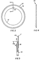
- Figs. 3, 4, and 5 show a typical knife in accordance with the invention.
- Fig. 3 shows a front view with a vacant center area 32, used to mount onto a knife carrier, which is then slid onto a knife shaft, and secured in position. Keyway 34 is used to prevent knife rotation on the knife carrier. The knife and knife carrier are held firmly on the knife shaft, which then rotates at the correct speed.
- Fig. 5 is a section of line 5-5; the rake angle is formed by the position of surface 36 relative to the horizontal. The rake angle generally is between 50 and 70 degrees.
- the opposite side of the knife, surface 38 generally has a small angle, called a face angle, or relief angle. This angle is always a positive angle, that is, the angle is ground into the knife face, typically less than 6 degrees. In some cases, however, no angle is used, and the face is perpendicular to the horizontal.
- the invention style slitter knives are usually arranged in series on a knife shaft or knife bar.
- a knife shaft or knife bar To such shafts, one male, another female, are mounted near each other, and then brought together, with the knives overlapping each other slightly. The faces of the male and female knives are then brought in to touch.
- a specific load is then applied to the end of one shaft, called the end load or preload, to ensure that the male and female knives remain in contact. This load is in the range of 8.9 to 2.2 N (2-5 pounds) depending on knife style.
- the paper sheet is then drawn between the two shafts and knife pairs. As the shafts rotate and the paper is pulled, individual strips of paper result.
- the overlap of the slitter knives is generally 375 to 1525 ⁇ m. (.015" to .060").
- the male knife shaft with knives is rotated a bit faster than the paper that moves through the knives. This is called the overdrive, or overspeed.
- the overdrive is 2-5%.
- Female knife shafts generally rotate at the same speed as the paper, or just slightly faster.
- the slitter knives of the prior art do not cut cleanly through the paper.
- the paper edge is similar to a tear, with paper fibers hanging on the edge, and the coatings protruding after being stretched.
- the knives of the invention will cut through the same paper but minimize the paper fibers on the edge, and the stretching of the coatings, thus reducing debris, and giving a better appearance. Further, the emulsion coatings are less stressed and so the edge is not as badly deformed.
- the high rake knives concentrate the slitting forces into a very narrow band along the edge, and so edge discoloration is minimized and confined to this narrow region. It is surprising that after many years of cutting with low rake knives, the change to a high rake knife has resulted in this improvement.
- the improvement in edge staining is particularly noticeable with color papers containing emulsions that are high chloride emulsions with Bromide at or near the surface.
- This slitting experiment consisted of slitting Ektacolor Royal III in a full factorial designed experiment. This resulted in 16 different slitting conditions. Refer to Table 1 above for the full layout of the experiment.
- the slitting conditions were: Upper (male) knife rake 40° & 60° Slitting speed (750 fpm & 1750 fpm) Web tension 3.3 and 17.8 N (.75 lb. and 4.0 lb.) Wrap angle through knives 0° & 90°
Landscapes
- Life Sciences & Earth Sciences (AREA)
- Forests & Forestry (AREA)
- Engineering & Computer Science (AREA)
- Mechanical Engineering (AREA)
- Nonmetal Cutting Devices (AREA)
- Photographic Processing Devices Using Wet Methods (AREA)
Claims (6)
- Verfahren zum Zuschneiden von fotografischem Printmaterial (23), gekennzeichnet durch den Schritt des Bereitstellens mindestens einer drehbaren Ambossschervorrichtung (24) und mindestens einer drehbaren Messerschervorrichtung (22), welche einen Schneidwinkel von 50 bis 70 Grad hat, und den Schritt des Transportierens des fotografischen Materials (23) zwischen dem Amboss (24) und dem Messer (22) hindurch zum Zuschneiden des Materials, wobei das mindestens eine Messer (22) den drehbaren Amboss (24) um 375 bis 1525 Micrometer überlappt und die Messer mit einer Geschwindigkeit angetrieben werden, die 2 bis 5% über der Geschwindigkeit liegt, mit der das Printmaterial transportiert wird.
- Verfahren nach Anspruch 1, dadurch gekennzeichnet, dass der Schneidwinkel etwa 60 Grad beträgt.
- Verfahren nach Anspruch 1 oder 2, dadurch gekennzeichnet, dass das mindestens eine drehbare Messer (22) auf einer Welle gelagert ist ebenso wie der mindestens eine Amboss (24) und dass das Printmaterial zwischen den beiden Wellen hindurch transportiert wird.
- Verfahren nach einem der Ansprüche 1 bis 3, dadurch gekennzeichnet, dass die seitliche Kraft des Messers (22) gegenüber dem Amboss (24) zwischen 9 und 23 Newton liegt.
- Verfahren nach einem der Ansprüche 1 bis 4, dadurch gekennzeichnet, dass das fotografische Material beim Zuschneiden derart positioniert ist, dass das Messer (22) mit der Emulsionsseite des Printmaterials in Berührung gelangt.
- Verfahren nach einem der Ansprüche 1 bis 5, dadurch gekennzeichnet, dass das drehbare Messer (22) einen Freiwinkel ausweist, der ein positiver Winkel von 1 bis 6 Grad ist.
Applications Claiming Priority (2)
| Application Number | Priority Date | Filing Date | Title |
|---|---|---|---|
| US09/064,403 US5974922A (en) | 1998-04-22 | 1998-04-22 | High rake knives for color paper slitting |
| US64403 | 1998-04-22 |
Publications (3)
| Publication Number | Publication Date |
|---|---|
| EP0953413A2 EP0953413A2 (de) | 1999-11-03 |
| EP0953413A3 EP0953413A3 (de) | 2002-01-23 |
| EP0953413B1 true EP0953413B1 (de) | 2003-11-19 |
Family
ID=22055739
Family Applications (1)
| Application Number | Title | Priority Date | Filing Date |
|---|---|---|---|
| EP99201132A Expired - Lifetime EP0953413B1 (de) | 1998-04-22 | 1999-04-12 | Verfahren zum Schneiden von fotografischen Materialien |
Country Status (3)
| Country | Link |
|---|---|
| US (1) | US5974922A (de) |
| EP (1) | EP0953413B1 (de) |
| DE (1) | DE69912874T2 (de) |
Families Citing this family (16)
| Publication number | Priority date | Publication date | Assignee | Title |
|---|---|---|---|---|
| DE60041794D1 (de) * | 1999-10-01 | 2009-04-23 | Fujifilm Corp | Vorrichtung zum Schneiden von bandförmigem, thermischem Bildmaterial |
| JP4132569B2 (ja) * | 2000-05-01 | 2008-08-13 | 富士フイルム株式会社 | スリッタ刃 |
| US7122235B2 (en) * | 2001-06-11 | 2006-10-17 | Eastman Kodak Company | Tack free cauterized edge for pressure sensitive adhesive web |
| US20030031838A1 (en) | 2001-06-11 | 2003-02-13 | Eastman Kodak Company | Tack free edge for pressure sensitive adhesive web |
| US7197970B2 (en) * | 2001-08-10 | 2007-04-03 | Ford Global Technologies, Llc | Apparatus for trimming metal |
| US20030029288A1 (en) * | 2001-08-10 | 2003-02-13 | Golovashchenko Sergey Fedorovich | Apparatus for trimming metal |
| US6820784B2 (en) | 2001-12-21 | 2004-11-23 | Eastman Kodak Company | Method of cutting a laminated web and reducing delamination |
| US7051911B2 (en) * | 2001-12-21 | 2006-05-30 | Eastman Kodak Company | Apparatus and method for cutting sheet materials |
| US7143674B2 (en) * | 2001-12-28 | 2006-12-05 | Eastman Kodak Company | Imaging element having improved crack propagation during conversion |
| US20040173074A1 (en) * | 2003-03-06 | 2004-09-09 | Li Ming M. | Apparatus for cutting sheet material |
| AU2003228296A1 (en) * | 2003-03-06 | 2004-09-30 | Alcoa Inc. | Apparatus and method for cutting sheet material |
| US7455004B2 (en) * | 2003-03-06 | 2008-11-25 | Alcoa Inc. | Apparatus and method for cutting sheet material |
| US7343946B2 (en) * | 2004-03-16 | 2008-03-18 | Key Knife, Inc. | High speed planer head |
| JP5328820B2 (ja) | 2011-02-02 | 2013-10-30 | 富士フイルム株式会社 | 被裁断物の裁断装置、インクジェット用紙の製造装置、インクジェット用紙の製造方法 |
| ITTO20120346A1 (it) * | 2012-04-18 | 2013-10-19 | Turmond S P A | Coltello multiplo rotante per il taglio longitudinale di nastri |
| US20150158194A1 (en) * | 2013-12-09 | 2015-06-11 | Knife Solutions, LLC | Slicing Blade System |
Family Cites Families (15)
| Publication number | Priority date | Publication date | Assignee | Title |
|---|---|---|---|---|
| US4274319A (en) * | 1977-06-27 | 1981-06-23 | Lenox Machine Company, Inc. | Slitter for high bulk traveling paper web material |
| US4247349A (en) * | 1979-05-14 | 1981-01-27 | American Can Company | Method and apparatus for cutting plastic film windows for cartons |
| US4643058A (en) * | 1984-05-10 | 1987-02-17 | Allied Corporation | Floating gang rotary slitting device and method |
| US4640165A (en) * | 1985-04-11 | 1987-02-03 | Baldwin Technology Corporation | Rotary knife system |
| DE3721423A1 (de) * | 1987-06-29 | 1989-01-19 | Gaemmerler Hagen | Schneidvorrichtung fuer mindestens zweilagige flaechengebilde, insbesondere papierprodukte |
| US5034263A (en) * | 1989-11-27 | 1991-07-23 | Eastman Kodak Company | Film laminate |
| FR2655588A1 (fr) * | 1989-12-12 | 1991-06-14 | Kodak Pathe | Couteau a levre et dispositif de coupe. |
| AT397481B (de) * | 1990-02-21 | 1994-04-25 | Boehler Ybbstalwerke | Kreismesserschere |
| US5103703A (en) * | 1990-03-14 | 1992-04-14 | Littleton Industrial Consultants, Inc. | Web severing apparatus and method |
| US5423240A (en) * | 1993-11-18 | 1995-06-13 | Detorre; Robert P. | Side-crowned carbide cutting blades and cutting devices |
| DE69516233T2 (de) * | 1994-11-07 | 2000-11-02 | Eastman Kodak Co., Rochester | Vorrichtung und Verfahren zum Langsscheiden von Bandmaterial |
| FR2732638B1 (fr) * | 1995-04-10 | 1997-05-09 | Kodak Pathe | Module de coupe pour produit en bande et dispositif de coupe equipe d'au moins un tel module |
| JP3581189B2 (ja) * | 1995-04-28 | 2004-10-27 | 株式会社イソワ | スリッタのシート受け装置 |
| GB9519747D0 (en) * | 1995-09-28 | 1995-11-29 | Cor Serve Limited | Rotary diecutting machine |
| DE19629561C2 (de) * | 1996-07-22 | 2003-07-03 | Slobodan Djuranovic | Segmentmesser für eine Rotationsschneidemaschine, dessen Umfang sich aus einer Vielzahl von Segmenten zusammengesetzt |
-
1998
- 1998-04-22 US US09/064,403 patent/US5974922A/en not_active Expired - Lifetime
-
1999
- 1999-04-12 EP EP99201132A patent/EP0953413B1/de not_active Expired - Lifetime
- 1999-04-12 DE DE69912874T patent/DE69912874T2/de not_active Expired - Fee Related
Also Published As
| Publication number | Publication date |
|---|---|
| EP0953413A3 (de) | 2002-01-23 |
| DE69912874T2 (de) | 2004-11-11 |
| DE69912874D1 (de) | 2003-12-24 |
| US5974922A (en) | 1999-11-02 |
| EP0953413A2 (de) | 1999-11-03 |
Similar Documents
| Publication | Publication Date | Title |
|---|---|---|
| EP0953413B1 (de) | Verfahren zum Schneiden von fotografischen Materialien | |
| US5700535A (en) | Sheet of labels, method of production and equipment | |
| US5360161A (en) | Apparatus for cutting photographic paper | |
| US3886031A (en) | Web lap splicer | |
| US5740709A (en) | Two stage continuous web cutting system and method | |
| US12023889B2 (en) | Apparatus including a tape applicator head | |
| US4505699A (en) | Apparatus for making envelopes from a continuous film sheet | |
| US4168643A (en) | Web slitter with presser roll | |
| DE60036480T2 (de) | Vorrichtung zum parallelen falzen in einer falzmaschine | |
| DE69211778T2 (de) | Verfahren und Vorrichtung zur Entfernung von Papierabfällen von einem kontinuierlichen Band photographicher Abzüge | |
| EP0924151A2 (de) | Apparat zum Falten und Schneiden einer Papierbahn | |
| CN110395456A (zh) | 一种钢纸自动分切及条码打印集成设备 | |
| NL1012999C1 (nl) | Werkwijze voor onder voortdurend contact uitsnijden van beeldmateriaal. | |
| JP2781674B2 (ja) | フィルム自動巻取装置 | |
| US20020166424A1 (en) | Method for producing photographic film | |
| SU626138A1 (ru) | Устройство дл разделени рулонов | |
| DE69720890T2 (de) | Elektrophotographisches Druckgerät | |
| JPS6216309Y2 (de) | ||
| JP3461103B2 (ja) | シート状物の切断装置および切断方法 | |
| US1574682A (en) | Machine for calendering and cutting sheets formed from plastic materials | |
| JP3033627B2 (ja) | 金属条のスリッティング装置 | |
| JPH0295656A (ja) | プラスチックフィルムの巻取方法 | |
| DE3782475T2 (de) | Schneidegeraet fuer photographische bilder. | |
| JP2003080490A (ja) | スリッタ | |
| KR20260019705A (ko) | 초박형 필름의 슬리팅 방법 |
Legal Events
| Date | Code | Title | Description |
|---|---|---|---|
| PUAI | Public reference made under article 153(3) epc to a published international application that has entered the european phase |
Free format text: ORIGINAL CODE: 0009012 |
|
| AK | Designated contracting states |
Kind code of ref document: A2 Designated state(s): AT BE CH CY DE DK ES FI FR GB GR IE IT LI LU MC NL PT SE Kind code of ref document: A2 Designated state(s): DE GB NL |
|
| AX | Request for extension of the european patent |
Free format text: AL;LT;LV;MK;RO;SI |
|
| PUAL | Search report despatched |
Free format text: ORIGINAL CODE: 0009013 |
|
| AK | Designated contracting states |
Kind code of ref document: A3 Designated state(s): AT BE CH CY DE DK ES FI FR GB GR IE IT LI LU MC NL PT SE |
|
| AX | Request for extension of the european patent |
Free format text: AL;LT;LV;MK;RO;SI |
|
| 17P | Request for examination filed |
Effective date: 20020606 |
|
| 17Q | First examination report despatched |
Effective date: 20020820 |
|
| AKX | Designation fees paid |
Free format text: DE GB NL |
|
| GRAH | Despatch of communication of intention to grant a patent |
Free format text: ORIGINAL CODE: EPIDOS IGRA |
|
| GRAS | Grant fee paid |
Free format text: ORIGINAL CODE: EPIDOSNIGR3 |
|
| GRAA | (expected) grant |
Free format text: ORIGINAL CODE: 0009210 |
|
| AK | Designated contracting states |
Kind code of ref document: B1 Designated state(s): DE GB NL |
|
| REG | Reference to a national code |
Ref country code: GB Ref legal event code: FG4D |
|
| REF | Corresponds to: |
Ref document number: 69912874 Country of ref document: DE Date of ref document: 20031224 Kind code of ref document: P |
|
| REG | Reference to a national code |
Ref country code: IE Ref legal event code: FG4D |
|
| PGFP | Annual fee paid to national office [announced via postgrant information from national office to epo] |
Ref country code: NL Payment date: 20040316 Year of fee payment: 6 |
|
| PGFP | Annual fee paid to national office [announced via postgrant information from national office to epo] |
Ref country code: DE Payment date: 20040430 Year of fee payment: 6 |
|
| PLBE | No opposition filed within time limit |
Free format text: ORIGINAL CODE: 0009261 |
|
| STAA | Information on the status of an ep patent application or granted ep patent |
Free format text: STATUS: NO OPPOSITION FILED WITHIN TIME LIMIT |
|
| 26N | No opposition filed |
Effective date: 20040820 |
|
| REG | Reference to a national code |
Ref country code: IE Ref legal event code: MM4A |
|
| PGFP | Annual fee paid to national office [announced via postgrant information from national office to epo] |
Ref country code: GB Payment date: 20050314 Year of fee payment: 7 |
|
| PG25 | Lapsed in a contracting state [announced via postgrant information from national office to epo] |
Ref country code: NL Free format text: LAPSE BECAUSE OF NON-PAYMENT OF DUE FEES Effective date: 20051101 Ref country code: DE Free format text: LAPSE BECAUSE OF NON-PAYMENT OF DUE FEES Effective date: 20051101 |
|
| NLV4 | Nl: lapsed or anulled due to non-payment of the annual fee |
Effective date: 20051101 |
|
| PG25 | Lapsed in a contracting state [announced via postgrant information from national office to epo] |
Ref country code: GB Free format text: LAPSE BECAUSE OF NON-PAYMENT OF DUE FEES Effective date: 20060412 |
|
| GBPC | Gb: european patent ceased through non-payment of renewal fee |
Effective date: 20060412 |