EP0953461A2 - Procédé de fabrication d'une roue - Google Patents
Procédé de fabrication d'une roue Download PDFInfo
- Publication number
- EP0953461A2 EP0953461A2 EP99108424A EP99108424A EP0953461A2 EP 0953461 A2 EP0953461 A2 EP 0953461A2 EP 99108424 A EP99108424 A EP 99108424A EP 99108424 A EP99108424 A EP 99108424A EP 0953461 A2 EP0953461 A2 EP 0953461A2
- Authority
- EP
- European Patent Office
- Prior art keywords
- disc
- flange
- flange means
- rim
- mounting
- Prior art date
- Legal status (The legal status is an assumption and is not a legal conclusion. Google has not performed a legal analysis and makes no representation as to the accuracy of the status listed.)
- Withdrawn
Links
- 238000004519 manufacturing process Methods 0.000 title claims abstract description 14
- 238000000034 method Methods 0.000 claims abstract description 29
- 238000010276 construction Methods 0.000 description 12
- 238000003466 welding Methods 0.000 description 10
- 125000006850 spacer group Chemical group 0.000 description 5
- 230000015572 biosynthetic process Effects 0.000 description 2
- 238000005553 drilling Methods 0.000 description 2
- 238000005755 formation reaction Methods 0.000 description 2
- 238000012986 modification Methods 0.000 description 1
- 230000004048 modification Effects 0.000 description 1
- 238000003825 pressing Methods 0.000 description 1
Images
Classifications
-
- B—PERFORMING OPERATIONS; TRANSPORTING
- B60—VEHICLES IN GENERAL
- B60B—VEHICLE WHEELS; CASTORS; AXLES FOR WHEELS OR CASTORS; INCREASING WHEEL ADHESION
- B60B3/00—Disc wheels, i.e. wheels with load-supporting disc body
- B60B3/002—Disc wheels, i.e. wheels with load-supporting disc body characterised by the shape of the disc
-
- B—PERFORMING OPERATIONS; TRANSPORTING
- B60—VEHICLES IN GENERAL
- B60B—VEHICLE WHEELS; CASTORS; AXLES FOR WHEELS OR CASTORS; INCREASING WHEEL ADHESION
- B60B21/00—Rims
- B60B21/02—Rims characterised by transverse section
-
- B—PERFORMING OPERATIONS; TRANSPORTING
- B60—VEHICLES IN GENERAL
- B60B—VEHICLE WHEELS; CASTORS; AXLES FOR WHEELS OR CASTORS; INCREASING WHEEL ADHESION
- B60B21/00—Rims
- B60B21/02—Rims characterised by transverse section
- B60B21/026—Rims characterised by transverse section the shape of rim well
-
- B—PERFORMING OPERATIONS; TRANSPORTING
- B60—VEHICLES IN GENERAL
- B60B—VEHICLE WHEELS; CASTORS; AXLES FOR WHEELS OR CASTORS; INCREASING WHEEL ADHESION
- B60B23/00—Attaching rim to wheel body
-
- B—PERFORMING OPERATIONS; TRANSPORTING
- B60—VEHICLES IN GENERAL
- B60B—VEHICLE WHEELS; CASTORS; AXLES FOR WHEELS OR CASTORS; INCREASING WHEEL ADHESION
- B60B23/00—Attaching rim to wheel body
- B60B23/06—Attaching rim to wheel body by screws, bolts, pins, or clips
- B60B23/10—Attaching rim to wheel body by screws, bolts, pins, or clips arranged axially
Definitions
- This invention relates to a method of making a wheel and more particularly but not exclusively a ground engaging wheel for a vehicle such as a tractor or an excavating/loading or like vehicle or machine.
- a vehicle such as a tractor or an excavating/loading or like vehicle or machine.
- the invention may be applied to a method of making a wheel for another purpose, although preferably for a ground engaging wheel of a vehicle or machine.
- Tractor wheels for example are made in different sizes to suit the vehicles on which the wheels are used. Tractor wheels made by different manufacturing methods are known.
- a tractor wheel may be made by fixing a, usually round, disc in a rim, for example by welding.
- the configuration of the wheel is thus fixed and to produce a range of wheels of different diameters it is necessary to make a range of rims of varying diameter, and to make a range of discs of matching size.
- a tractor wheel may be made by securing in the rim e.g. by welding, a plurality of lugs to which the disc is attached at discrete mounting positions, as described in UK patent application GB2285957A.
- the disc is usually nominally square with the corners removed to provide mounting positions.
- Such a construction has the advantage over a fixed disc wheel that the disc may be mounted on either side of the lugs, with or without spacers, and the disc may be reversed, so as to provide a variety of wheel configurations so that the tracking between a pair of such wheels on a common axle, may be changed.
- This is a desirable feature for farmers for example who may require the tracking to be set to match the distance between furrows for example, in a field.
- the disc is usually attached to the lugs by fastenings such as bolts which are releasable to enable track adjustments to be made.
- a construction similar to the lug construction described may be used but in which there is a flange means secured in the rim, e.g. by welding, rather than lugs.
- a disc is thus fixed in the rim by attaching the disc to the flange means, usually at discrete mounting positions provided by the flange means, again by means of releasable fastenings.
- the first aspect of the invention we provide a method of making a wheel from a rim selected from a plurality of rims of different nominal diameters, a plurality of flange means of different configurations, and a disc, the method comprising selecting from the plurality of rims a rim of a desired diameter, selecting from the plurality of flange means a flange means of an appropriate configuration so that when the flange means is secured to the rim, the flange means provides a mounting for the disc, and mounting the disc in the rim by attaching the disc to the flange means.
- the disc may be circular around its periphery and may be attached to the flange means around substantially the entire circumference of the disc, for example by welding.
- the method comprises attaching the disc to the flange means at a plurality of mounting stations provided by the flange means.
- the disc may be nominally square around its periphery, with the corners of the square removed to provide positions at which the disc is attached to the flange means at the mounting stations.
- the disc is preferably attached to the flange means by reusable releasable fastening means such as threaded fasteners which may provide formations whereby the fasteners may readily be released and re-used, so as to provide an adjustable wheel.
- the attachment of the disc to flange means may utilise spacers as desired so that the wheel tracking of a pair of wheels on a common axle may be adjusted to a desired tracking.
- the disc may be attached to the flange means by permanent fasteners by which we mean fasteners which cannot be readily released and re-used, such as rivets, for one example, or even threaded fasteners which when tightened to a desired torque, become permanently damaged and are not re-usable.
- fasteners which cannot be readily released and re-used, such as rivets, for one example, or even threaded fasteners which when tightened to a desired torque, become permanently damaged and are not re-usable.
- a formation necessary to tighten and release such a fastener may break off so that the faster cannot then readily be released.
- the wheel is not adjustable by for example a vehicle operator, although the disc and flange means may be separated e.g. by drilling out the fastener so that the wheel may be repaired for example, by replacing a component part thereof, i.e. the rim or the disc.
- the flange means may each comprises a first generally circular part which is adapted to be secured to the rim and a second generally circular flange part which is adapted to extend radially inwardly of the rim and provide the mounting for the disc, the method comprising attaching the disc to the second flange part.
- the flange means may be of alternative configurations by virtue of at least some of the second flange parts of the plurality of flange means being longer in a direction in use radially inwardly of the rim, than others of the second flange parts, so that the method may comprise selecting a flange means from the plurality of flange means, in which the second flange part is of a sufficient length so that in use the second flange part extends radially inwardly sufficiently far for the disc to be attached to the second flange part of the selected flange means.
- a typical range of wheels comprises three wheels of different diameter.
- the method may comprise providing at least three alternative configurations of flange means, the first configuration having a second flange part of a length greater than the length of the second flange part of the second configuration of flange means, and the second flange part of the second configuration flange means being of a length greater than the second flange part of the third configuration of flange means.
- a second aspect of the invention we provide a method of making a wheel from a rim and a disc, utilising mounting means secured to the run to provide a mounting for the disc in the rim, wherein the method comprises attaching the disc to the mounting means by permanent fasteners which cannot be readily released and re-used.
- a set of wheels each comprising a rim, a disc and a flange means providing a mounting for the disc in the rim, each of the wheels of the set having a rim with a different nominal diameter, a disc of common configuration to all the wheels of the set, and a flange means of a different configuration to the flange means of the other wheel or wheels of the set.
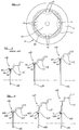
- a wheel 10 being a tractor wheel comprising a rim 11 on which a tyre 12 is mounted.
- a disc 15 by means of which the wheel 10 may be secured relative to an axle on a tractor.
- the disc 15 is of a nominally square configuration with the corners removed and the disc 15 is fixed in the rim 11 by a plurality of fastenings 18 which engage a flange means 20 at four mounting stations.
- the flange means 20 extends circumferentially around the rim 11 and is secured in the rim by means of welding.
- a wheel is produced to the required diameter by taking a rim 11a, 11b, 11c of the appropriate diameter, and securing in the rim a flange means 20.
- the flange means 20 comprises a first part 21 and second flange part 22, integrally provided preferably, by pressing for example.
- the first part 21 is secured by welding in the rim 11a, 11b or 11c and the second part 22 is transverse to the first flange part 21 and extends radially inwardly of the rim 11a, 11b, 11c and provides a mounting for a disc 15a, 15b, 15c.
- the flange means 20 are common to the three wheels 10a, 10b, 10c of the range, necessarily, three different size and configuration discs 15a, 15b and 15c are required in order to produce a range of three wheels.
- the discs 15a, 15b and 15c are large and expensive to produce and accordingly production of three discs of alternative configuration, is expensive.
- the discs 15a, 15b, 15c may be attached to the second part 22 of the flange means 20 in each respective wheel construction, either permanently e.g. by welding, or preferably by means of fasteners 18, utilising spacers as necessary so that the wheel produced is an adjustable wheel, the disc 15a, 15b, 15c being attachable to either side of the flange means 20 and spacers being used as required, so that the tracking distance between a pair of such wheels on a common axle may be adjusted.
- a range of three wheels 10a, 10b, 10c is produced without a requirement for producing three discs 15a, 15b, 15c of alternative configurations.
- Each of the flange means 20a, 20b, 20c comprises a first part 21a, 21b, 21c which is secured to the respective rim 11a, 11b, 11c by welding for example, and a second flange part 22a, 22b, 22c which again is integrally provided with the first flange part 21a, 21b, 21c, but extends in use radially inwardly of the wheel 10a, 10b, 10c.
- the second part 22a of flange means 20a is shorter in length (radially inwardly of the wheel) than the second part 22b of the second flange means 20b. This in turn is of shorter length than the second flange part 22c of the flange means 20c of the wheel construction 10c, in which the rim 11c is of the greatest diameter.
- flange means 20a, 20b and 20c are each of a different configuration so as to provide an appropriate mounting for a common disc 15 within the different diameter rims 11a, 11b and 11c.
- the flange means 20a of the smallest diameter wheel construction 10a is of a simple L shape, with one limb of the L providing the flange part 21a which is secured to the rim 11a, and the second limb of the L providing the second flange part 22a.
- the second flange part 22b of the second flange means 20b is of a more convoluted configuration so as to provide the necessary strength for the longer second flange part 22b of the flange means 20b, and the second flange part 22c of the flange means 20c of the largest diameter wheel construction 10c is of even more convoluted configuration, so as to provide even greater strength to support the rim 11c relative to the disc 15.
- the common disc 15 may be attached to the respective flange means 20a, 20b, 20c in any desired manner. Where the disc 15 is circular around its periphery, it may be welded to the respective flange means 20a, 20b, 20c. Alternatively, the disc 15 may be attached to its respective flange means 20a, 20b, 20c by reusable threaded fasteners such as nuts and bolts, and spacers may be utilised so that the wheel 10a, 10b, 10c is adjustable, for different track widths between a pair of such wheels on a common axis.
- reusable threaded fasteners such as nuts and bolts
- the disc 15 may be attached to its respective flange means 20a, 20b, 20c by fastenings which are not reusable.
- fastenings are rivets, or fasteners which are threaded and which may be tightened to a pre-determined torque before the fasteners become permanently damaged so that they cannot subsequently be readily released.
- non-reusable fasteners may be utilised.
- a range of three wheel sizes may be produced from the components described.
- only two wheels of alternative size, but utilising a common disc configuration may be made, or more than three wheels of different diameters may be produced.
- the flange means 20a, 20b and 20c have been secured in the rim 11a, 11b, 11c by welding, any other suitable technique for securing the flange means 20a, 20b, 20c in position in the rim may alternatively be used.
- the flange means 20a and 20b and 20c obviously need to be of different configurations so as to enable a common disc 15 to be used with different diameter rims 11a, 11b, 11c, but one or more of the flange means 20a, 20b, 20c may be of alternative configurations to those shown in figure 3.
- the invention may be applied to produce a range of wheels for other uses, from common components, for example, wheels for excavators, loaders or other working machines, or for vehicles in general.
- the invention is utilised to produce a range of ground engaging wheels.
- the disc 15 is of a simple plain construction, but it will be appreciated by those skilled in the art, that a disc 15 more usually 0is of a complex shape which is what makes its production in three alternative sizes, so expensive.
Landscapes
- Engineering & Computer Science (AREA)
- Mechanical Engineering (AREA)
- Automatic Assembly (AREA)
- Compositions Of Macromolecular Compounds (AREA)
- Turbine Rotor Nozzle Sealing (AREA)
- Braking Arrangements (AREA)
- Shaping Metal By Deep-Drawing, Or The Like (AREA)
Applications Claiming Priority (2)
| Application Number | Priority Date | Filing Date | Title |
|---|---|---|---|
| GB9809117A GB2336813B (en) | 1998-04-30 | 1998-04-30 | Method of making a wheel |
| GB9809117 | 1998-04-30 |
Publications (2)
| Publication Number | Publication Date |
|---|---|
| EP0953461A2 true EP0953461A2 (fr) | 1999-11-03 |
| EP0953461A3 EP0953461A3 (fr) | 2000-09-06 |
Family
ID=10831159
Family Applications (1)
| Application Number | Title | Priority Date | Filing Date |
|---|---|---|---|
| EP99108424A Withdrawn EP0953461A3 (fr) | 1998-04-30 | 1999-04-29 | Procédé de fabrication d'une roue |
Country Status (4)
| Country | Link |
|---|---|
| US (1) | US6179388B1 (fr) |
| EP (1) | EP0953461A3 (fr) |
| BR (1) | BR9901325A (fr) |
| GB (1) | GB2336813B (fr) |
Cited By (3)
| Publication number | Priority date | Publication date | Assignee | Title |
|---|---|---|---|---|
| EP2081777A4 (fr) * | 2006-10-31 | 2011-04-13 | Crocodile Corp Ltd | Structure de roue |
| CN105291704A (zh) * | 2015-10-13 | 2016-02-03 | 嘉善振杨汽车部件有限公司 | 一种新型轮胎 |
| CN105291703A (zh) * | 2015-10-13 | 2016-02-03 | 嘉善振杨汽车部件有限公司 | 一种驱动轮 |
Families Citing this family (1)
| Publication number | Priority date | Publication date | Assignee | Title |
|---|---|---|---|---|
| TWI256352B (en) * | 2004-09-22 | 2006-06-11 | Ting-Fang Wang | Aluminum alloy wheel rim and manufacturing method thereof |
Citations (2)
| Publication number | Priority date | Publication date | Assignee | Title |
|---|---|---|---|---|
| US5380071A (en) | 1993-03-15 | 1995-01-10 | Motor Wheel Corporation | Vehicle wheel and method of manufacture of the same |
| GB2285957A (en) | 1994-01-25 | 1995-08-02 | Gkn Sankey Ltd | Wheel |
Family Cites Families (11)
| Publication number | Priority date | Publication date | Assignee | Title |
|---|---|---|---|---|
| GB241788A (en) * | 1925-03-16 | 1925-10-29 | Wallace Rosche Gillam | Improvements in rim structures for mounting tires on wheels |
| US1652752A (en) * | 1927-10-08 | 1927-12-13 | Motor Ind Inc | Wheel |
| US1880641A (en) * | 1929-03-20 | 1932-10-04 | Goodyear Tire & Rubber | Vehicle wheel |
| US2083066A (en) * | 1933-07-27 | 1937-06-08 | Motor Wheel Corp | Vehicle wheel |
| US2209030A (en) * | 1938-09-30 | 1940-07-23 | Int Harvester Co | Wheel |
| US2237481A (en) * | 1940-02-13 | 1941-04-08 | Ferro Casimiro | Vehicle wheel |
| US2363182A (en) * | 1942-04-06 | 1944-11-21 | Motor Wheel Corp | Vehicle wheel |
| US4836261A (en) * | 1987-03-27 | 1989-06-06 | Motor Wheel Corporation | Safety tire and take-apart wheel construction |
| CA2047019C (fr) * | 1991-07-15 | 1995-02-07 | Verne H. Berry | Jante de roue en deux parties |
| GB9524952D0 (en) * | 1995-12-06 | 1996-02-07 | Gkn Sankey Ltd | Wheels |
| US6027176A (en) * | 1997-10-14 | 2000-02-22 | Titan International, Inc. | Wheel |
-
1998
- 1998-04-30 GB GB9809117A patent/GB2336813B/en not_active Expired - Lifetime
-
1999
- 1999-04-27 US US09/300,046 patent/US6179388B1/en not_active Expired - Lifetime
- 1999-04-29 BR BR9901325-8A patent/BR9901325A/pt not_active IP Right Cessation
- 1999-04-29 EP EP99108424A patent/EP0953461A3/fr not_active Withdrawn
Patent Citations (2)
| Publication number | Priority date | Publication date | Assignee | Title |
|---|---|---|---|---|
| US5380071A (en) | 1993-03-15 | 1995-01-10 | Motor Wheel Corporation | Vehicle wheel and method of manufacture of the same |
| GB2285957A (en) | 1994-01-25 | 1995-08-02 | Gkn Sankey Ltd | Wheel |
Cited By (3)
| Publication number | Priority date | Publication date | Assignee | Title |
|---|---|---|---|---|
| EP2081777A4 (fr) * | 2006-10-31 | 2011-04-13 | Crocodile Corp Ltd | Structure de roue |
| CN105291704A (zh) * | 2015-10-13 | 2016-02-03 | 嘉善振杨汽车部件有限公司 | 一种新型轮胎 |
| CN105291703A (zh) * | 2015-10-13 | 2016-02-03 | 嘉善振杨汽车部件有限公司 | 一种驱动轮 |
Also Published As
| Publication number | Publication date |
|---|---|
| US6179388B1 (en) | 2001-01-30 |
| GB9809117D0 (en) | 1998-07-01 |
| GB2336813A (en) | 1999-11-03 |
| GB2336813B (en) | 2002-04-03 |
| BR9901325A (pt) | 2001-03-06 |
| EP0953461A3 (fr) | 2000-09-06 |
Similar Documents
| Publication | Publication Date | Title |
|---|---|---|
| US3935891A (en) | Tire traction device | |
| EP0692641A2 (fr) | Dispositif de fixation pour éléments ayant des alésages à entraxes variables | |
| JP2004516997A (ja) | ホイールアセンブリ | |
| US5197785A (en) | Two piece adapter rim for wheel assemblies | |
| JPH04504897A (ja) | 自動車車輪を取付けるためのロックナットと六角ナットとの組合せ | |
| EP4253085B1 (fr) | Jante réutilisable pour pneus non pneumatiques | |
| WO2009049762A1 (fr) | Jante à plusieurs parties | |
| US6179388B1 (en) | Method of making a wheel | |
| US5938291A (en) | Wheels | |
| US7287819B2 (en) | Vehicle wheel and adapter | |
| US7178880B2 (en) | Wheel centering pin, kit and method | |
| US5906418A (en) | Auxiliary traction wheel for a vehicle | |
| US4004838A (en) | Vehicle hub assembly | |
| EP0664227B1 (fr) | Roue | |
| DE3641095A1 (de) | Dichtungsanordnung fuer ein rad mit teilbarer felge | |
| US6715843B2 (en) | Wheel mounting assembly and method | |
| US20180354297A1 (en) | Traction device for a vehicle with dual wheels | |
| US3713701A (en) | Detachable auxiliary tractor tire and wheel attachment means | |
| US20130061994A1 (en) | Tire bead assist device wheel | |
| KR102468628B1 (ko) | 조립식 자동차용 휠 구조체 | |
| KR200369156Y1 (ko) | 타이어 휠과 차축의 체결구조 | |
| US12508835B2 (en) | Agricultural wheel | |
| KR20040027877A (ko) | 휠지지 조립체와 허브 | |
| KR20090055664A (ko) | 차량용 휠너트 풀림 방지 장치 | |
| JPH01309801A (ja) | 小径車輪 |
Legal Events
| Date | Code | Title | Description |
|---|---|---|---|
| PUAI | Public reference made under article 153(3) epc to a published international application that has entered the european phase |
Free format text: ORIGINAL CODE: 0009012 |
|
| AK | Designated contracting states |
Kind code of ref document: A2 Designated state(s): AT DE DK ES FR GB IT |
|
| AX | Request for extension of the european patent |
Free format text: AL;LT;LV;MK;RO;SI |
|
| PUAL | Search report despatched |
Free format text: ORIGINAL CODE: 0009013 |
|
| AK | Designated contracting states |
Kind code of ref document: A3 Designated state(s): AT BE CH CY DE DK ES FI FR GB GR IE IT LI LU MC NL PT SE |
|
| AX | Request for extension of the european patent |
Free format text: AL;LT;LV;MK;RO;SI |
|
| RIC1 | Information provided on ipc code assigned before grant |
Free format text: 7B 60B 1/04 A, 7B 60B 3/04 B, 7B 60B 23/00 B |
|
| 17P | Request for examination filed |
Effective date: 20010302 |
|
| AKX | Designation fees paid |
Free format text: AT DE DK ES FR GB IT |
|
| 17Q | First examination report despatched |
Effective date: 20020625 |
|
| RTI1 | Title (correction) |
Free format text: METHOD OF MAKING WHEELS OF DIFFERENT DIAMETERS |
|
| GRAH | Despatch of communication of intention to grant a patent |
Free format text: ORIGINAL CODE: EPIDOS IGRA |
|
| STAA | Information on the status of an ep patent application or granted ep patent |
Free format text: STATUS: THE APPLICATION IS DEEMED TO BE WITHDRAWN |
|
| 18D | Application deemed to be withdrawn |
Effective date: 20030604 |