EP0953465A2 - Coulisse de guidage - Google Patents
Coulisse de guidage Download PDFInfo
- Publication number
- EP0953465A2 EP0953465A2 EP99108419A EP99108419A EP0953465A2 EP 0953465 A2 EP0953465 A2 EP 0953465A2 EP 99108419 A EP99108419 A EP 99108419A EP 99108419 A EP99108419 A EP 99108419A EP 0953465 A2 EP0953465 A2 EP 0953465A2
- Authority
- EP
- European Patent Office
- Prior art keywords
- guide
- stiffening element
- opening
- link
- cover
- Prior art date
- Legal status (The legal status is an assumption and is not a legal conclusion. Google has not performed a legal analysis and makes no representation as to the accuracy of the status listed.)
- Withdrawn
Links
Images


Classifications
-
- B—PERFORMING OPERATIONS; TRANSPORTING
- B60—VEHICLES IN GENERAL
- B60J—WINDOWS, WINDSCREENS, NON-FIXED ROOFS, DOORS, OR SIMILAR DEVICES FOR VEHICLES; REMOVABLE EXTERNAL PROTECTIVE COVERINGS SPECIALLY ADAPTED FOR VEHICLES
- B60J7/00—Non-fixed roofs; Roofs with movable panels, e.g. rotary sunroofs
- B60J7/02—Non-fixed roofs; Roofs with movable panels, e.g. rotary sunroofs of sliding type, e.g. comprising guide shoes
- B60J7/022—Sliding roof trays or assemblies
Definitions
- the invention relates to a guide link for a cover openable vehicle roof with a link body connected to the cover, which comprises at least one slot-shaped opening, the opening being a Guideway forms or the inclusion of one having the guideway
- the guide body serves.
- Such a guide link is for example from DE 35 29 118 C2 or DE 196 23 945 C1 known.
- the guideway of the guide link serves to slidably accommodate one Link pin of a cover actuation mechanism for pivoting and / or moving of the cover in the vehicle's longitudinal direction. So that the cover with vertical loads, such as they are caused, among other things, by wind load, and do not tend to vibrate the link body of a generic guide link has sufficient rigidity and have torsional strength. Also in overload operation, which occurs, for example, when the cover actuation mechanism in the case of a frame fixed to the vehicle frozen cover is pressed, the backdrop must not deform plastically.
- guide scenes with very long guideways are particularly critical, as with Lid actuation mechanisms are used, in which the link pin is attached directly a slider of a guide rail running in the direction of displacement of the cover is appropriate.
- Guide scenes of the type mentioned are therefore often considered relatively thick Sheet metal part executed, which may also have bends. Especially Sufficiently high webs must remain above and below the opening in order to achieve a avoid plastic deformation of the guideway under load and the elastic To minimize deformation and tendency to vibrate. This has the consequence that generic Guide scenes, if the link body consists of a sheet metal part, a high Have weight and require a large installation height. Will be with leadership scenes of the type of backdrop body made of plastic, this must be dimensioned even stronger for reasons of strength and takes up even more installation space Claim.
- the invention specified in claim 1 is based on the object of a backdrop to create the type mentioned above, which is characterized by high strength, nevertheless with low material thickness and narrow webs above and below the Breakthrough comes along and without great manufacturing effort can be produced inexpensively.
- This task is performed in a management setting with the features of the generic term Claim 1 solved in that at least one stiffening element is provided, which spans the breakthrough like a bridge at least in one area and Connects material areas of the link body on both sides of the opening.
- the stiffening elements reinforce the backdrop body, by reducing the free resilient length of the breakthrough, and can target High load points can be arranged without increasing the overall height.
- the reliable function of the backdrop is also significantly improved in overload operation.
- the guide slot according to the invention is suitable for use in all types of Openable vehicle roofs such as sunroofs, sunroofs, sliding / sunroofs or slat roofs.
- the lid can be one piece or multi-part cover.
- the stiffening element is preferably U-shaped and with the Link body connected positively and / or non-positively. It can be of a U shape curved sheet metal strips are formed, which latches with the link body and / or riveted. The metal strip can cover almost the entire length of the Extend guideway.
- the stiffening element can also be U-shaped in a structurally particularly simple manner curved metal body can be designed with a circular cross section, which in Receiving holes of the link body is caulked or tumbled, the Link body also suitably consists of metal.
- the stiffening element can be integral connected to the link body or formed integrally therewith.
- the one-piece design is particularly useful for a plastic link body, in which the at least one stiffening element is also injected during the spraying process becomes.
- the stiffening element can also be used as an form essential U-shaped plastic encapsulation of the link body, whereby one has great freedom in shaping and the stiffening element strength and can optimize space.
- the guideway will not break through the backdrop body itself but formed by a guide body made of plastic, which is in the breakthrough of the link body, it is appropriate to the guide body and at least form a stiffening element in one piece and together on the link body to spray.
- the stiffening element particularly advantageously tensions the material areas on both sides of the Breakthrough resiliently towards each other, so that the walls of the The guideway can be slightly biased in the transverse direction and a slidable recorded guide pin rests against it without play.
- the stiffening elements preferably span a region of the opening of the Link body, in which a section of the guideway is located, the transition from a closed position of the lid to a ventilation position with a fixed Roof skin of the vehicle corresponds to the raised rear edge of the cover.
- a stiffening element expediently reinforces the breakthrough in a section of the Guideway that corresponds to the ventilation position. This ensures that in Cover positions in which overload operation can occur frequently, the guide link is particularly rigid.
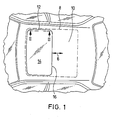
- FIG. 1 there is a roof opening in a fixed roof skin 10 of a vehicle 12 provided, either closed or completely or partially by a cover 14 can be exposed.
- the lid 14 is operated by a lid actuation mechanism known type driven, which is supported on a frame 8 and a lifting or Lowering a rear edge 16 of the lid 14 and the lid displacement in Movement direction 6 is used.
- a guide link 18 is shown, the one elongated link body 20 made of metal with a substantially in the longitudinal direction of the link body extending slot-shaped opening 22. Holding pieces 34 are used to fasten the link body 20 to the cover 14.
- a plastic guide body 26 is molded, the one Guide track 23, which of an upper and a lower wall 24, 25th is formed.
- the walls 24 and 25 are spaced apart by the thickness of one corresponds between them movable pin 44.
- the link body is articulated via a pin 43 with a web 40 one front slider 36 connected, the slider 36 in a in the direction of displacement 6 of the cover extending guide rail 46 is slidably received.
- the link pin 44 is carried by a web 42 of a rear slide 38, which is also slidably supported along the guide rail 46.
- the rear Slider 38 is part of the lid actuation mechanism and is known from a drive, not shown, moves in the direction of displacement 6 via compression-resistant cable, the link pin 44 depending on the distance between the two sliders 36 and 38 along the Guide ban 23 is moved. This will cause the longitudinal movement of the rear Slider 38 in a rotational movement of the cover 14 about the longitudinal axis of the pin 43 transformed.
- the link pin 44 is located in a front section 28 of FIG Guideway 23, the lid trailing edge 16 is issued over the fixed roof skin 10. As shown in FIG. 2, the link pin 44 takes a central section 30 of the Guideway 23, the cover 14 is in the closed position. Is the backdrop pin 44 finally in a rear section 32, the rear edge 16 of the cover 14 is below the fixed roof skin 10 pivoted so that the cover 14 by moving both Sliders 36 and 38 can be moved in the direction of displacement 6.
- the link body 20 has an L-shaped cross section with a bevel 52 and is provided with two stiffening elements 48 which the opening 22 in Divide the direction of displacement 6 into three sections of approximately the same length and material areas Connect with each other above and below the opening 22.
- the stiffening elements 48 are formed by a U-shaped round steel, the legs of each end have a shoulder which is inserted into a bore 50 of the link body 20 and with this is positively and non-positively connected in the form of a countersunk head rivet connection.
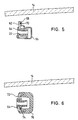
- the stiffening element is as U-shaped spring clip 56 formed, the legs of which is also U-shaped Grip link body 54.
- Each leg of the spring clip 56 has stamped Locking bracket 60, which engage positively in receptacles 58 of the link body 54.
- the legs of the spring clip 56 are biased towards one another to ensure a secure fit on the link body 54 and at the same time the upper and lower wall 24 or 25 of the guide body 26 slightly elastic press together so that the link pin 44 follows the guideway 23 without play.
- FIG. 5 shows a spring bracket 66 which is also designed in the essential U-shaped stiffening element and an L-shaped link body 62, in the opening 22, a guide body 64 is molded from plastic.
- the lower Leg of the spring clip 66 engages around the short leg of the link body 62 form-fitting, whereas an extension 68 on the upper leg of the spring clip 66 is integrally formed with the long leg of the link body 62 via welding points 70 is connected.
- the spring clip 66 extends in the longitudinal direction of the link body 62 over almost the entire length of the guideway.
- the stiffening element is a U-shaped plastic extrusion 76, which has an upper and a lower leg a likewise U-shaped link body 72 connects. Passages 74 in the Legs of the link body 72 are used for the positive connection of the Plastic encapsulation 76 with the link body 72.
- the guide body 64 can be designed as a separate component or optionally with plastic extrusion coating 76 be made in one piece.
Landscapes
- Engineering & Computer Science (AREA)
- Mechanical Engineering (AREA)
- Body Structure For Vehicles (AREA)
- Fittings On The Vehicle Exterior For Carrying Loads, And Devices For Holding Or Mounting Articles (AREA)
Applications Claiming Priority (3)
| Application Number | Priority Date | Filing Date | Title |
|---|---|---|---|
| DE19819678 | 1998-05-02 | ||
| DE19819678A DE19819678C1 (de) | 1998-05-02 | 1998-05-02 | Führungskulisse |
| US09/303,541 US6189963B1 (en) | 1998-05-02 | 1999-05-03 | Guide crank |
Publications (2)
| Publication Number | Publication Date |
|---|---|
| EP0953465A2 true EP0953465A2 (fr) | 1999-11-03 |
| EP0953465A3 EP0953465A3 (fr) | 2001-04-04 |
Family
ID=26045918
Family Applications (1)
| Application Number | Title | Priority Date | Filing Date |
|---|---|---|---|
| EP99108419A Withdrawn EP0953465A3 (fr) | 1998-05-02 | 1999-04-29 | Coulisse de guidage |
Country Status (4)
| Country | Link |
|---|---|
| US (1) | US6189963B1 (fr) |
| EP (1) | EP0953465A3 (fr) |
| JP (1) | JP4242505B2 (fr) |
| DE (1) | DE19819678C1 (fr) |
Families Citing this family (3)
| Publication number | Priority date | Publication date | Assignee | Title |
|---|---|---|---|---|
| NL1014296C2 (nl) * | 2000-02-04 | 2001-08-07 | Inalfa Ind Bv | Open-dakconstructie voor een voertuig. |
| DE10011747C2 (de) * | 2000-03-13 | 2002-02-28 | Webasto Vehicle Sys Int Gmbh | Kulissenelement zur festen Anbringung an einem Deckelelement |
| CN105774497A (zh) * | 2016-03-11 | 2016-07-20 | 安徽省地坤汽车天窗科技有限公司 | 一种汽车天窗的支撑运动机构 |
Citations (3)
| Publication number | Priority date | Publication date | Assignee | Title |
|---|---|---|---|---|
| DE3529118C1 (fr) | 1985-08-14 | 1990-01-25 | Adam Opel Ag, 6090 Ruesselsheim, De | |
| DE4405742C1 (de) | 1994-02-23 | 1995-05-04 | Wahl Peter Gmbh & Co | Führungskulisse für Schiebedeckel an Schiebehebedachkonstruktionen für Kraftfahrzeuge |
| DE19623945C1 (de) | 1996-06-15 | 1997-07-24 | Webasto Karosseriesysteme | Wasserrinnen-Halterung an einem Schiebehebedach |
Family Cites Families (4)
| Publication number | Priority date | Publication date | Assignee | Title |
|---|---|---|---|---|
| FR2205429B1 (fr) * | 1972-11-08 | 1977-04-08 | Peugeot & Renault | |
| DE3009199A1 (de) * | 1980-03-11 | 1981-09-17 | Löhr & Bromkamp GmbH, 6050 Offenbach | Lagerungsanordnung einer ueber ein gleichlaufdrehgelenk antreibbaren radnabe |
| DE3910894C3 (de) * | 1988-04-05 | 2000-12-14 | Aisin Seiki | Bewegungsmechanismus für einen Deckel eines Fahrzeugdachausschnittes |
| DE9407234U1 (de) * | 1994-04-30 | 1994-09-01 | Paul Zitzmann GmbH & Co KG -Druckgußwerk Stockheim-, 96342 Stockheim | Kulisse für ein verschiebbares und/oder aufstellbares Dachteil eines Kraftfahrzeuges |
-
1998
- 1998-05-02 DE DE19819678A patent/DE19819678C1/de not_active Expired - Fee Related
-
1999
- 1999-03-26 JP JP08421099A patent/JP4242505B2/ja not_active Expired - Fee Related
- 1999-04-29 EP EP99108419A patent/EP0953465A3/fr not_active Withdrawn
- 1999-05-03 US US09/303,541 patent/US6189963B1/en not_active Expired - Fee Related
Patent Citations (3)
| Publication number | Priority date | Publication date | Assignee | Title |
|---|---|---|---|---|
| DE3529118C1 (fr) | 1985-08-14 | 1990-01-25 | Adam Opel Ag, 6090 Ruesselsheim, De | |
| DE4405742C1 (de) | 1994-02-23 | 1995-05-04 | Wahl Peter Gmbh & Co | Führungskulisse für Schiebedeckel an Schiebehebedachkonstruktionen für Kraftfahrzeuge |
| DE19623945C1 (de) | 1996-06-15 | 1997-07-24 | Webasto Karosseriesysteme | Wasserrinnen-Halterung an einem Schiebehebedach |
Also Published As
| Publication number | Publication date |
|---|---|
| JPH11314526A (ja) | 1999-11-16 |
| US6189963B1 (en) | 2001-02-20 |
| JP4242505B2 (ja) | 2009-03-25 |
| EP0953465A3 (fr) | 2001-04-04 |
| DE19819678C1 (de) | 1999-07-15 |
Similar Documents
| Publication | Publication Date | Title |
|---|---|---|
| DE19638156B4 (de) | Aufbau für oberen Karosserieabschnitt einer Fahrzeugkarosserie | |
| EP0584496B1 (fr) | Toit de voiture | |
| DE60015446T2 (de) | Konstruktion eines öffnungsfähigen Kraftfahrzeugdaches | |
| DE4229867C2 (de) | Aufbau eines Sonnendachs eines selbstfahrenden Fahrzeugs und Verfahren zur Montage desselben | |
| DE19700165C2 (de) | Schiebehebedach | |
| EP1780354A2 (fr) | Agencement d'une porte coulissante de véhicule automobile | |
| DE10333781B4 (de) | Öffnungsfähiges Fahrzeugdach | |
| DE3901093A1 (de) | Kraftfahrzeugtuer | |
| DE2759029C2 (fr) | ||
| DE69702305T2 (de) | Öffnungsvorrichtung für einen mit einer plane ausgerüsteten behälter | |
| DE60014745T2 (de) | Konstruktion eines öffnungsfähiges Fahrzeugdaches | |
| DE3727719C2 (de) | Rahmenanordnung für ein Fahrzeugdach | |
| DE4005790C2 (fr) | ||
| DE570520C (de) | Tuer, insbesondere fuer geschlossene Wagenkasten bei Kraftfahrzeugen | |
| DE60011522T2 (de) | Konstruktion eines öffnungsfähigen Fahrzeugdaches | |
| DE4438104C1 (de) | Schiebehimmelanordnung für ein Fahrzeugdach | |
| EP0218020A2 (fr) | Toit ouvrant pour véhicules automobiles | |
| DE10158174B4 (de) | Schiebehebedach für Fahrzeuge | |
| EP1616738A1 (fr) | Construction de toit coulissant pour véhicule automobile | |
| DE19819678C1 (de) | Führungskulisse | |
| DE102005032437A1 (de) | Fahrzeugdach mit einem bewegbaren Dachteil | |
| DE10039842B4 (de) | Führungsschiene für eine bewegbare Fensterscheibe | |
| DE19911022C2 (de) | Schiebefenster für ein Kraftfahrzeug | |
| DE19732700A1 (de) | Antriebsvorrichtung für ein Deckelteil eines Fahrzeugdaches | |
| DE3425273A1 (de) | Gleitschuh fuer ein fahrzeug-schiebedach |
Legal Events
| Date | Code | Title | Description |
|---|---|---|---|
| PUAI | Public reference made under article 153(3) epc to a published international application that has entered the european phase |
Free format text: ORIGINAL CODE: 0009012 |
|
| AK | Designated contracting states |
Kind code of ref document: A2 Designated state(s): DE GB NL |
|
| AX | Request for extension of the european patent |
Free format text: AL;LT;LV;MK;RO;SI |
|
| PUAL | Search report despatched |
Free format text: ORIGINAL CODE: 0009013 |
|
| AK | Designated contracting states |
Kind code of ref document: A3 Designated state(s): AT BE CH CY DE DK ES FI FR GB GR IE IT LI LU MC NL PT SE |
|
| AX | Request for extension of the european patent |
Free format text: AL;LT;LV;MK;RO;SI |
|
| RIC1 | Information provided on ipc code assigned before grant |
Free format text: 7B 60J 7/05 A, 7B 60J 7/057 B |
|
| 17P | Request for examination filed |
Effective date: 20010502 |
|
| AKX | Designation fees paid |
Free format text: DE GB NL |
|
| GRAP | Despatch of communication of intention to grant a patent |
Free format text: ORIGINAL CODE: EPIDOSNIGR1 |
|
| STAA | Information on the status of an ep patent application or granted ep patent |
Free format text: STATUS: THE APPLICATION IS DEEMED TO BE WITHDRAWN |
|
| 18D | Application deemed to be withdrawn |
Effective date: 20040723 |