EP0953467B1 - Vorrichtung zur Kraftübertragung für ein Kraftfahrzeug - Google Patents
Vorrichtung zur Kraftübertragung für ein Kraftfahrzeug Download PDFInfo
- Publication number
- EP0953467B1 EP0953467B1 EP99107435A EP99107435A EP0953467B1 EP 0953467 B1 EP0953467 B1 EP 0953467B1 EP 99107435 A EP99107435 A EP 99107435A EP 99107435 A EP99107435 A EP 99107435A EP 0953467 B1 EP0953467 B1 EP 0953467B1
- Authority
- EP
- European Patent Office
- Prior art keywords
- engine
- motor
- generator
- transmission system
- torque
- Prior art date
- Legal status (The legal status is an assumption and is not a legal conclusion. Google has not performed a legal analysis and makes no representation as to the accuracy of the status listed.)
- Expired - Lifetime
Links
Images


Classifications
-
- B—PERFORMING OPERATIONS; TRANSPORTING
- B60—VEHICLES IN GENERAL
- B60W—CONJOINT CONTROL OF VEHICLE SUB-UNITS OF DIFFERENT TYPE OR DIFFERENT FUNCTION; CONTROL SYSTEMS SPECIALLY ADAPTED FOR HYBRID VEHICLES; ROAD VEHICLE DRIVE CONTROL SYSTEMS FOR PURPOSES NOT RELATED TO THE CONTROL OF A PARTICULAR SUB-UNIT
- B60W20/00—Control systems specially adapted for hybrid vehicles
- B60W20/40—Controlling the engagement or disengagement of prime movers, e.g. for transition between prime movers
-
- B—PERFORMING OPERATIONS; TRANSPORTING
- B60—VEHICLES IN GENERAL
- B60K—ARRANGEMENT OR MOUNTING OF PROPULSION UNITS OR OF TRANSMISSIONS IN VEHICLES; ARRANGEMENT OR MOUNTING OF PLURAL DIVERSE PRIME-MOVERS IN VEHICLES; AUXILIARY DRIVES FOR VEHICLES; INSTRUMENTATION OR DASHBOARDS FOR VEHICLES; ARRANGEMENTS IN CONNECTION WITH COOLING, AIR INTAKE, GAS EXHAUST OR FUEL SUPPLY OF PROPULSION UNITS IN VEHICLES
- B60K6/00—Arrangement or mounting of plural diverse prime-movers for mutual or common propulsion, e.g. hybrid propulsion systems comprising electric motors and internal combustion engines
- B60K6/20—Arrangement or mounting of plural diverse prime-movers for mutual or common propulsion, e.g. hybrid propulsion systems comprising electric motors and internal combustion engines the prime-movers consisting of electric motors and internal combustion engines, e.g. HEVs
- B60K6/42—Arrangement or mounting of plural diverse prime-movers for mutual or common propulsion, e.g. hybrid propulsion systems comprising electric motors and internal combustion engines the prime-movers consisting of electric motors and internal combustion engines, e.g. HEVs characterised by the architecture of the hybrid electric vehicle
- B60K6/44—Series-parallel type
- B60K6/442—Series-parallel switching type
-
- B—PERFORMING OPERATIONS; TRANSPORTING
- B60—VEHICLES IN GENERAL
- B60K—ARRANGEMENT OR MOUNTING OF PROPULSION UNITS OR OF TRANSMISSIONS IN VEHICLES; ARRANGEMENT OR MOUNTING OF PLURAL DIVERSE PRIME-MOVERS IN VEHICLES; AUXILIARY DRIVES FOR VEHICLES; INSTRUMENTATION OR DASHBOARDS FOR VEHICLES; ARRANGEMENTS IN CONNECTION WITH COOLING, AIR INTAKE, GAS EXHAUST OR FUEL SUPPLY OF PROPULSION UNITS IN VEHICLES
- B60K6/00—Arrangement or mounting of plural diverse prime-movers for mutual or common propulsion, e.g. hybrid propulsion systems comprising electric motors and internal combustion engines
- B60K6/20—Arrangement or mounting of plural diverse prime-movers for mutual or common propulsion, e.g. hybrid propulsion systems comprising electric motors and internal combustion engines the prime-movers consisting of electric motors and internal combustion engines, e.g. HEVs
- B60K6/42—Arrangement or mounting of plural diverse prime-movers for mutual or common propulsion, e.g. hybrid propulsion systems comprising electric motors and internal combustion engines the prime-movers consisting of electric motors and internal combustion engines, e.g. HEVs characterised by the architecture of the hybrid electric vehicle
- B60K6/48—Parallel type
-
- B—PERFORMING OPERATIONS; TRANSPORTING
- B60—VEHICLES IN GENERAL
- B60K—ARRANGEMENT OR MOUNTING OF PROPULSION UNITS OR OF TRANSMISSIONS IN VEHICLES; ARRANGEMENT OR MOUNTING OF PLURAL DIVERSE PRIME-MOVERS IN VEHICLES; AUXILIARY DRIVES FOR VEHICLES; INSTRUMENTATION OR DASHBOARDS FOR VEHICLES; ARRANGEMENTS IN CONNECTION WITH COOLING, AIR INTAKE, GAS EXHAUST OR FUEL SUPPLY OF PROPULSION UNITS IN VEHICLES
- B60K6/00—Arrangement or mounting of plural diverse prime-movers for mutual or common propulsion, e.g. hybrid propulsion systems comprising electric motors and internal combustion engines
- B60K6/20—Arrangement or mounting of plural diverse prime-movers for mutual or common propulsion, e.g. hybrid propulsion systems comprising electric motors and internal combustion engines the prime-movers consisting of electric motors and internal combustion engines, e.g. HEVs
- B60K6/50—Architecture of the driveline characterised by arrangement or kind of transmission units
- B60K6/54—Transmission for changing ratio
- B60K6/547—Transmission for changing ratio the transmission being a stepped gearing
-
- B—PERFORMING OPERATIONS; TRANSPORTING
- B60—VEHICLES IN GENERAL
- B60L—PROPULSION OF ELECTRICALLY-PROPELLED VEHICLES; SUPPLYING ELECTRIC POWER FOR AUXILIARY EQUIPMENT OF ELECTRICALLY-PROPELLED VEHICLES; ELECTRODYNAMIC BRAKE SYSTEMS FOR VEHICLES IN GENERAL; MAGNETIC SUSPENSION OR LEVITATION FOR VEHICLES; MONITORING OPERATING VARIABLES OF ELECTRICALLY-PROPELLED VEHICLES; ELECTRIC SAFETY DEVICES FOR ELECTRICALLY-PROPELLED VEHICLES
- B60L50/00—Electric propulsion with power supplied within the vehicle
- B60L50/10—Electric propulsion with power supplied within the vehicle using propulsion power supplied by engine-driven generators, e.g. generators driven by combustion engines
- B60L50/16—Electric propulsion with power supplied within the vehicle using propulsion power supplied by engine-driven generators, e.g. generators driven by combustion engines with provision for separate direct mechanical propulsion
-
- B—PERFORMING OPERATIONS; TRANSPORTING
- B60—VEHICLES IN GENERAL
- B60L—PROPULSION OF ELECTRICALLY-PROPELLED VEHICLES; SUPPLYING ELECTRIC POWER FOR AUXILIARY EQUIPMENT OF ELECTRICALLY-PROPELLED VEHICLES; ELECTRODYNAMIC BRAKE SYSTEMS FOR VEHICLES IN GENERAL; MAGNETIC SUSPENSION OR LEVITATION FOR VEHICLES; MONITORING OPERATING VARIABLES OF ELECTRICALLY-PROPELLED VEHICLES; ELECTRIC SAFETY DEVICES FOR ELECTRICALLY-PROPELLED VEHICLES
- B60L50/00—Electric propulsion with power supplied within the vehicle
- B60L50/50—Electric propulsion with power supplied within the vehicle using propulsion power supplied by batteries or fuel cells
- B60L50/60—Electric propulsion with power supplied within the vehicle using propulsion power supplied by batteries or fuel cells using power supplied by batteries
- B60L50/61—Electric propulsion with power supplied within the vehicle using propulsion power supplied by batteries or fuel cells using power supplied by batteries by batteries charged by engine-driven generators, e.g. series hybrid electric vehicles
-
- B—PERFORMING OPERATIONS; TRANSPORTING
- B60—VEHICLES IN GENERAL
- B60W—CONJOINT CONTROL OF VEHICLE SUB-UNITS OF DIFFERENT TYPE OR DIFFERENT FUNCTION; CONTROL SYSTEMS SPECIALLY ADAPTED FOR HYBRID VEHICLES; ROAD VEHICLE DRIVE CONTROL SYSTEMS FOR PURPOSES NOT RELATED TO THE CONTROL OF A PARTICULAR SUB-UNIT
- B60W10/00—Conjoint control of vehicle sub-units of different type or different function
- B60W10/04—Conjoint control of vehicle sub-units of different type or different function including control of propulsion units
- B60W10/06—Conjoint control of vehicle sub-units of different type or different function including control of propulsion units including control of combustion engines
-
- B—PERFORMING OPERATIONS; TRANSPORTING
- B60—VEHICLES IN GENERAL
- B60W—CONJOINT CONTROL OF VEHICLE SUB-UNITS OF DIFFERENT TYPE OR DIFFERENT FUNCTION; CONTROL SYSTEMS SPECIALLY ADAPTED FOR HYBRID VEHICLES; ROAD VEHICLE DRIVE CONTROL SYSTEMS FOR PURPOSES NOT RELATED TO THE CONTROL OF A PARTICULAR SUB-UNIT
- B60W10/00—Conjoint control of vehicle sub-units of different type or different function
- B60W10/10—Conjoint control of vehicle sub-units of different type or different function including control of change-speed gearings
- B60W10/11—Stepped gearings
-
- B—PERFORMING OPERATIONS; TRANSPORTING
- B60—VEHICLES IN GENERAL
- B60W—CONJOINT CONTROL OF VEHICLE SUB-UNITS OF DIFFERENT TYPE OR DIFFERENT FUNCTION; CONTROL SYSTEMS SPECIALLY ADAPTED FOR HYBRID VEHICLES; ROAD VEHICLE DRIVE CONTROL SYSTEMS FOR PURPOSES NOT RELATED TO THE CONTROL OF A PARTICULAR SUB-UNIT
- B60W10/00—Conjoint control of vehicle sub-units of different type or different function
- B60W10/24—Conjoint control of vehicle sub-units of different type or different function including control of energy storage means
- B60W10/26—Conjoint control of vehicle sub-units of different type or different function including control of energy storage means for electrical energy, e.g. batteries or capacitors
-
- B—PERFORMING OPERATIONS; TRANSPORTING
- B60—VEHICLES IN GENERAL
- B60W—CONJOINT CONTROL OF VEHICLE SUB-UNITS OF DIFFERENT TYPE OR DIFFERENT FUNCTION; CONTROL SYSTEMS SPECIALLY ADAPTED FOR HYBRID VEHICLES; ROAD VEHICLE DRIVE CONTROL SYSTEMS FOR PURPOSES NOT RELATED TO THE CONTROL OF A PARTICULAR SUB-UNIT
- B60W20/00—Control systems specially adapted for hybrid vehicles
- B60W20/20—Control strategies involving selection of hybrid configuration, e.g. selection between series or parallel configuration
-
- B—PERFORMING OPERATIONS; TRANSPORTING
- B60—VEHICLES IN GENERAL
- B60W—CONJOINT CONTROL OF VEHICLE SUB-UNITS OF DIFFERENT TYPE OR DIFFERENT FUNCTION; CONTROL SYSTEMS SPECIALLY ADAPTED FOR HYBRID VEHICLES; ROAD VEHICLE DRIVE CONTROL SYSTEMS FOR PURPOSES NOT RELATED TO THE CONTROL OF A PARTICULAR SUB-UNIT
- B60W30/00—Purposes of road vehicle drive control systems not related to the control of a particular sub-unit, e.g. of systems using conjoint control of vehicle sub-units
- B60W30/18—Propelling the vehicle
- B60W30/19—Improvement of gear change, e.g. by synchronisation or smoothing gear shift
-
- F—MECHANICAL ENGINEERING; LIGHTING; HEATING; WEAPONS; BLASTING
- F16—ENGINEERING ELEMENTS AND UNITS; GENERAL MEASURES FOR PRODUCING AND MAINTAINING EFFECTIVE FUNCTIONING OF MACHINES OR INSTALLATIONS; THERMAL INSULATION IN GENERAL
- F16H—GEARING
- F16H3/00—Toothed gearings for conveying rotary motion with variable gear ratio or for reversing rotary motion
- F16H3/02—Toothed gearings for conveying rotary motion with variable gear ratio or for reversing rotary motion without gears having orbital motion
- F16H3/08—Toothed gearings for conveying rotary motion with variable gear ratio or for reversing rotary motion without gears having orbital motion exclusively or essentially with continuously meshing gears, that can be disengaged from their shafts
- F16H3/12—Toothed gearings for conveying rotary motion with variable gear ratio or for reversing rotary motion without gears having orbital motion exclusively or essentially with continuously meshing gears, that can be disengaged from their shafts with means for synchronisation not incorporated in the clutches
- F16H3/126—Toothed gearings for conveying rotary motion with variable gear ratio or for reversing rotary motion without gears having orbital motion exclusively or essentially with continuously meshing gears, that can be disengaged from their shafts with means for synchronisation not incorporated in the clutches using an electric drive
-
- B—PERFORMING OPERATIONS; TRANSPORTING
- B60—VEHICLES IN GENERAL
- B60K—ARRANGEMENT OR MOUNTING OF PROPULSION UNITS OR OF TRANSMISSIONS IN VEHICLES; ARRANGEMENT OR MOUNTING OF PLURAL DIVERSE PRIME-MOVERS IN VEHICLES; AUXILIARY DRIVES FOR VEHICLES; INSTRUMENTATION OR DASHBOARDS FOR VEHICLES; ARRANGEMENTS IN CONNECTION WITH COOLING, AIR INTAKE, GAS EXHAUST OR FUEL SUPPLY OF PROPULSION UNITS IN VEHICLES
- B60K1/00—Arrangement or mounting of electrical propulsion units
- B60K1/02—Arrangement or mounting of electrical propulsion units comprising more than one electric motor
-
- B—PERFORMING OPERATIONS; TRANSPORTING
- B60—VEHICLES IN GENERAL
- B60K—ARRANGEMENT OR MOUNTING OF PROPULSION UNITS OR OF TRANSMISSIONS IN VEHICLES; ARRANGEMENT OR MOUNTING OF PLURAL DIVERSE PRIME-MOVERS IN VEHICLES; AUXILIARY DRIVES FOR VEHICLES; INSTRUMENTATION OR DASHBOARDS FOR VEHICLES; ARRANGEMENTS IN CONNECTION WITH COOLING, AIR INTAKE, GAS EXHAUST OR FUEL SUPPLY OF PROPULSION UNITS IN VEHICLES
- B60K6/00—Arrangement or mounting of plural diverse prime-movers for mutual or common propulsion, e.g. hybrid propulsion systems comprising electric motors and internal combustion engines
- B60K6/20—Arrangement or mounting of plural diverse prime-movers for mutual or common propulsion, e.g. hybrid propulsion systems comprising electric motors and internal combustion engines the prime-movers consisting of electric motors and internal combustion engines, e.g. HEVs
- B60K6/42—Arrangement or mounting of plural diverse prime-movers for mutual or common propulsion, e.g. hybrid propulsion systems comprising electric motors and internal combustion engines the prime-movers consisting of electric motors and internal combustion engines, e.g. HEVs characterised by the architecture of the hybrid electric vehicle
- B60K6/48—Parallel type
- B60K2006/4825—Electric machine connected or connectable to gearbox input shaft
-
- B—PERFORMING OPERATIONS; TRANSPORTING
- B60—VEHICLES IN GENERAL
- B60W—CONJOINT CONTROL OF VEHICLE SUB-UNITS OF DIFFERENT TYPE OR DIFFERENT FUNCTION; CONTROL SYSTEMS SPECIALLY ADAPTED FOR HYBRID VEHICLES; ROAD VEHICLE DRIVE CONTROL SYSTEMS FOR PURPOSES NOT RELATED TO THE CONTROL OF A PARTICULAR SUB-UNIT
- B60W10/00—Conjoint control of vehicle sub-units of different type or different function
- B60W10/04—Conjoint control of vehicle sub-units of different type or different function including control of propulsion units
- B60W10/08—Conjoint control of vehicle sub-units of different type or different function including control of propulsion units including control of electric propulsion units, e.g. motors or generators
-
- B—PERFORMING OPERATIONS; TRANSPORTING
- B60—VEHICLES IN GENERAL
- B60W—CONJOINT CONTROL OF VEHICLE SUB-UNITS OF DIFFERENT TYPE OR DIFFERENT FUNCTION; CONTROL SYSTEMS SPECIALLY ADAPTED FOR HYBRID VEHICLES; ROAD VEHICLE DRIVE CONTROL SYSTEMS FOR PURPOSES NOT RELATED TO THE CONTROL OF A PARTICULAR SUB-UNIT
- B60W20/00—Control systems specially adapted for hybrid vehicles
- B60W20/50—Control strategies for responding to system failures, e.g. for fault diagnosis, failsafe operation or limp mode
-
- B—PERFORMING OPERATIONS; TRANSPORTING
- B60—VEHICLES IN GENERAL
- B60W—CONJOINT CONTROL OF VEHICLE SUB-UNITS OF DIFFERENT TYPE OR DIFFERENT FUNCTION; CONTROL SYSTEMS SPECIALLY ADAPTED FOR HYBRID VEHICLES; ROAD VEHICLE DRIVE CONTROL SYSTEMS FOR PURPOSES NOT RELATED TO THE CONTROL OF A PARTICULAR SUB-UNIT
- B60W2510/00—Input parameters relating to a particular sub-units
- B60W2510/06—Combustion engines, Gas turbines
- B60W2510/0638—Engine speed
-
- B—PERFORMING OPERATIONS; TRANSPORTING
- B60—VEHICLES IN GENERAL
- B60W—CONJOINT CONTROL OF VEHICLE SUB-UNITS OF DIFFERENT TYPE OR DIFFERENT FUNCTION; CONTROL SYSTEMS SPECIALLY ADAPTED FOR HYBRID VEHICLES; ROAD VEHICLE DRIVE CONTROL SYSTEMS FOR PURPOSES NOT RELATED TO THE CONTROL OF A PARTICULAR SUB-UNIT
- B60W2510/00—Input parameters relating to a particular sub-units
- B60W2510/08—Electric propulsion units
- B60W2510/081—Speed
-
- B—PERFORMING OPERATIONS; TRANSPORTING
- B60—VEHICLES IN GENERAL
- B60W—CONJOINT CONTROL OF VEHICLE SUB-UNITS OF DIFFERENT TYPE OR DIFFERENT FUNCTION; CONTROL SYSTEMS SPECIALLY ADAPTED FOR HYBRID VEHICLES; ROAD VEHICLE DRIVE CONTROL SYSTEMS FOR PURPOSES NOT RELATED TO THE CONTROL OF A PARTICULAR SUB-UNIT
- B60W2510/00—Input parameters relating to a particular sub-units
- B60W2510/24—Energy storage means
- B60W2510/242—Energy storage means for electrical energy
- B60W2510/244—Charge state
-
- B—PERFORMING OPERATIONS; TRANSPORTING
- B60—VEHICLES IN GENERAL
- B60W—CONJOINT CONTROL OF VEHICLE SUB-UNITS OF DIFFERENT TYPE OR DIFFERENT FUNCTION; CONTROL SYSTEMS SPECIALLY ADAPTED FOR HYBRID VEHICLES; ROAD VEHICLE DRIVE CONTROL SYSTEMS FOR PURPOSES NOT RELATED TO THE CONTROL OF A PARTICULAR SUB-UNIT
- B60W2540/00—Input parameters relating to occupants
- B60W2540/10—Accelerator pedal position
-
- B—PERFORMING OPERATIONS; TRANSPORTING
- B60—VEHICLES IN GENERAL
- B60W—CONJOINT CONTROL OF VEHICLE SUB-UNITS OF DIFFERENT TYPE OR DIFFERENT FUNCTION; CONTROL SYSTEMS SPECIALLY ADAPTED FOR HYBRID VEHICLES; ROAD VEHICLE DRIVE CONTROL SYSTEMS FOR PURPOSES NOT RELATED TO THE CONTROL OF A PARTICULAR SUB-UNIT
- B60W2540/00—Input parameters relating to occupants
- B60W2540/12—Brake pedal position
-
- B—PERFORMING OPERATIONS; TRANSPORTING
- B60—VEHICLES IN GENERAL
- B60W—CONJOINT CONTROL OF VEHICLE SUB-UNITS OF DIFFERENT TYPE OR DIFFERENT FUNCTION; CONTROL SYSTEMS SPECIALLY ADAPTED FOR HYBRID VEHICLES; ROAD VEHICLE DRIVE CONTROL SYSTEMS FOR PURPOSES NOT RELATED TO THE CONTROL OF A PARTICULAR SUB-UNIT
- B60W2540/00—Input parameters relating to occupants
- B60W2540/16—Ratio selector position
-
- B—PERFORMING OPERATIONS; TRANSPORTING
- B60—VEHICLES IN GENERAL
- B60W—CONJOINT CONTROL OF VEHICLE SUB-UNITS OF DIFFERENT TYPE OR DIFFERENT FUNCTION; CONTROL SYSTEMS SPECIALLY ADAPTED FOR HYBRID VEHICLES; ROAD VEHICLE DRIVE CONTROL SYSTEMS FOR PURPOSES NOT RELATED TO THE CONTROL OF A PARTICULAR SUB-UNIT
- B60W2710/00—Output or target parameters relating to a particular sub-units
- B60W2710/06—Combustion engines, Gas turbines
- B60W2710/0666—Engine torque
-
- B—PERFORMING OPERATIONS; TRANSPORTING
- B60—VEHICLES IN GENERAL
- B60W—CONJOINT CONTROL OF VEHICLE SUB-UNITS OF DIFFERENT TYPE OR DIFFERENT FUNCTION; CONTROL SYSTEMS SPECIALLY ADAPTED FOR HYBRID VEHICLES; ROAD VEHICLE DRIVE CONTROL SYSTEMS FOR PURPOSES NOT RELATED TO THE CONTROL OF A PARTICULAR SUB-UNIT
- B60W2710/00—Output or target parameters relating to a particular sub-units
- B60W2710/08—Electric propulsion units
- B60W2710/083—Torque
-
- B—PERFORMING OPERATIONS; TRANSPORTING
- B60—VEHICLES IN GENERAL
- B60W—CONJOINT CONTROL OF VEHICLE SUB-UNITS OF DIFFERENT TYPE OR DIFFERENT FUNCTION; CONTROL SYSTEMS SPECIALLY ADAPTED FOR HYBRID VEHICLES; ROAD VEHICLE DRIVE CONTROL SYSTEMS FOR PURPOSES NOT RELATED TO THE CONTROL OF A PARTICULAR SUB-UNIT
- B60W2710/00—Output or target parameters relating to a particular sub-units
- B60W2710/10—Change speed gearings
- B60W2710/105—Output torque
-
- F—MECHANICAL ENGINEERING; LIGHTING; HEATING; WEAPONS; BLASTING
- F16—ENGINEERING ELEMENTS AND UNITS; GENERAL MEASURES FOR PRODUCING AND MAINTAINING EFFECTIVE FUNCTIONING OF MACHINES OR INSTALLATIONS; THERMAL INSULATION IN GENERAL
- F16H—GEARING
- F16H61/00—Control functions within control units of change-speed- or reversing-gearings for conveying rotary motion ; Control of exclusively fluid gearing, friction gearing, gearings with endless flexible members or other particular types of gearing
- F16H61/04—Smoothing ratio shift
- F16H61/0403—Synchronisation before shifting
- F16H2061/0422—Synchronisation before shifting by an electric machine, e.g. by accelerating or braking the input shaft
-
- F—MECHANICAL ENGINEERING; LIGHTING; HEATING; WEAPONS; BLASTING
- F16—ENGINEERING ELEMENTS AND UNITS; GENERAL MEASURES FOR PRODUCING AND MAINTAINING EFFECTIVE FUNCTIONING OF MACHINES OR INSTALLATIONS; THERMAL INSULATION IN GENERAL
- F16H—GEARING
- F16H61/00—Control functions within control units of change-speed- or reversing-gearings for conveying rotary motion ; Control of exclusively fluid gearing, friction gearing, gearings with endless flexible members or other particular types of gearing
- F16H61/04—Smoothing ratio shift
- F16H2061/0425—Bridging torque interruption
- F16H2061/0433—Bridging torque interruption by torque supply with an electric motor
-
- Y—GENERAL TAGGING OF NEW TECHNOLOGICAL DEVELOPMENTS; GENERAL TAGGING OF CROSS-SECTIONAL TECHNOLOGIES SPANNING OVER SEVERAL SECTIONS OF THE IPC; TECHNICAL SUBJECTS COVERED BY FORMER USPC CROSS-REFERENCE ART COLLECTIONS [XRACs] AND DIGESTS
- Y02—TECHNOLOGIES OR APPLICATIONS FOR MITIGATION OR ADAPTATION AGAINST CLIMATE CHANGE
- Y02T—CLIMATE CHANGE MITIGATION TECHNOLOGIES RELATED TO TRANSPORTATION
- Y02T10/00—Road transport of goods or passengers
- Y02T10/60—Other road transportation technologies with climate change mitigation effect
- Y02T10/62—Hybrid vehicles
-
- Y—GENERAL TAGGING OF NEW TECHNOLOGICAL DEVELOPMENTS; GENERAL TAGGING OF CROSS-SECTIONAL TECHNOLOGIES SPANNING OVER SEVERAL SECTIONS OF THE IPC; TECHNICAL SUBJECTS COVERED BY FORMER USPC CROSS-REFERENCE ART COLLECTIONS [XRACs] AND DIGESTS
- Y02—TECHNOLOGIES OR APPLICATIONS FOR MITIGATION OR ADAPTATION AGAINST CLIMATE CHANGE
- Y02T—CLIMATE CHANGE MITIGATION TECHNOLOGIES RELATED TO TRANSPORTATION
- Y02T10/00—Road transport of goods or passengers
- Y02T10/60—Other road transportation technologies with climate change mitigation effect
- Y02T10/70—Energy storage systems for electromobility, e.g. batteries
-
- Y—GENERAL TAGGING OF NEW TECHNOLOGICAL DEVELOPMENTS; GENERAL TAGGING OF CROSS-SECTIONAL TECHNOLOGIES SPANNING OVER SEVERAL SECTIONS OF THE IPC; TECHNICAL SUBJECTS COVERED BY FORMER USPC CROSS-REFERENCE ART COLLECTIONS [XRACs] AND DIGESTS
- Y02—TECHNOLOGIES OR APPLICATIONS FOR MITIGATION OR ADAPTATION AGAINST CLIMATE CHANGE
- Y02T—CLIMATE CHANGE MITIGATION TECHNOLOGIES RELATED TO TRANSPORTATION
- Y02T10/00—Road transport of goods or passengers
- Y02T10/60—Other road transportation technologies with climate change mitigation effect
- Y02T10/7072—Electromobility specific charging systems or methods for batteries, ultracapacitors, supercapacitors or double-layer capacitors
-
- Y—GENERAL TAGGING OF NEW TECHNOLOGICAL DEVELOPMENTS; GENERAL TAGGING OF CROSS-SECTIONAL TECHNOLOGIES SPANNING OVER SEVERAL SECTIONS OF THE IPC; TECHNICAL SUBJECTS COVERED BY FORMER USPC CROSS-REFERENCE ART COLLECTIONS [XRACs] AND DIGESTS
- Y10—TECHNICAL SUBJECTS COVERED BY FORMER USPC
- Y10S—TECHNICAL SUBJECTS COVERED BY FORMER USPC CROSS-REFERENCE ART COLLECTIONS [XRACs] AND DIGESTS
- Y10S903/00—Hybrid electric vehicles, HEVS
- Y10S903/902—Prime movers comprising electrical and internal combustion motors
- Y10S903/903—Prime movers comprising electrical and internal combustion motors having energy storing means, e.g. battery, capacitor
- Y10S903/904—Component specially adapted for hev
- Y10S903/915—Specific drive or transmission adapted for hev
- Y10S903/917—Specific drive or transmission adapted for hev with transmission for changing gear ratio
- Y10S903/919—Stepped shift
-
- Y—GENERAL TAGGING OF NEW TECHNOLOGICAL DEVELOPMENTS; GENERAL TAGGING OF CROSS-SECTIONAL TECHNOLOGIES SPANNING OVER SEVERAL SECTIONS OF THE IPC; TECHNICAL SUBJECTS COVERED BY FORMER USPC CROSS-REFERENCE ART COLLECTIONS [XRACs] AND DIGESTS
- Y10—TECHNICAL SUBJECTS COVERED BY FORMER USPC
- Y10S—TECHNICAL SUBJECTS COVERED BY FORMER USPC CROSS-REFERENCE ART COLLECTIONS [XRACs] AND DIGESTS
- Y10S903/00—Hybrid electric vehicles, HEVS
- Y10S903/902—Prime movers comprising electrical and internal combustion motors
- Y10S903/903—Prime movers comprising electrical and internal combustion motors having energy storing means, e.g. battery, capacitor
- Y10S903/945—Characterized by control of gearing, e.g. control of transmission ratio
Definitions
- the present invention relates to a construction of a power train system comprising an internal combustion engine (hereinafter referred to as an engine), an electric power device (hereinafter referred to as a motor) and a power transmission apparatus, and particularly to a power transmission apparatus adapted to enhance the transmission efficiency of the power train system.
- an engine an internal combustion engine
- an electric power device hereinafter referred to as a motor
- a power transmission apparatus adapted to enhance the transmission efficiency of the power train system.
- Japanese Patent Laid-Open No. Hei 8-98322 discloses a known example using a power transmission apparatus adapted to enhance the transmission efficiency of the power train system.
- DE 44 44 545 A1 describes a hybrid vehicle including an ineternal combustion engine and an electric motor, both used to provide locomotion together with a traction battery to feed the electric motor.
- a separate generator charges a battery and is driven by the AC engine or by one module within it working under single point operation.
- a decoupling device is provided to separate the engine or the engine module from the vehicle drive during battery charging, and a clutch is situated between the generator and the engine. Flywheels are integrated into the generator and the electric motor, and work in conjunction with the AC engine or its separate modules.
- JP-50030223 A discloses a gear transmission apparatus of a composite electric vehicle comprising a planetary gear consisting of a sun gear, a carrier, and a ring gear connected to the output shaft of an engine via a first switching clutch, a second shaft from the planetary gear is connected to the output shaft of a generator and a third shaft from the planetary gear is connected to a driving shaft of a vehicle, so that an M-mode in which the vehicle is driven only by a motor is realized by connecting the output shaft of the motor and the third shaft via a gear transmission.
- An M-E mode in which the vehicle is compositely driven by the engine and the motor is realized by providing a battery and a controller between the generator and the motor and electronically connecting them with each other, and an E-mode in which the vehicle is driven by the engine is realized by providing a second switching clutch on the second shaft or between the first and the second shafts.
- JP-08098322 A discloses a method of switching the running mode from the series hybrid running to the parallel hybrid running mode without a switching shock by controlling a generator torque as to have the revolution of a generator and the revolution of a motor to be practically consistent with each other.
- the generation of an inertia torque of the generator can be suppressed, thereby improving the fuel economy of the vehicle.
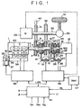
- FIG. 1 shows a construction of a hybrid automobile system according to one embodiment of the present invention.
- an output shaft 2 of an engine 1 has a gear 4 on the engine side for low speed having a meshing gear 3, a gear 6 on the engine side for high speed having a meshing gear 5, a hub 7 and a sleeve 8 for directly connecting the gear 4 on the engine side for low speed or the gear 6 on the engine side for high speed with the output shaft 2.
- a stopper (not shown) is provided so that the gear 4 on the engine side for low speed and the gear 6 on the engine side for high speed may not move in an axial direction of the output shaft 2.
- the hub 7 is internally provided with grooves (not shown) engaged with a plurality of grooves 9 of the output shaft 2.
- the hub 7 is movable in an axial direction of the output shaft 2, but the movement of the hub 7 in a rotational direction of the output shaft 2 is limited. Thereby, the torque output from the engine 1 is transmitted to the hub and the sleeve.
- the sleeve 8 In order to transmit the torque from the engine 1 to the gear 4 on the engine side for low speed or the gear 6 on the engine side for high speed, it is necessary to move the sleeve 8 in an axial direction of the output shaft 2 to directly connect the meshing gear 3 or 5 to the hub 7.
- the meshing gears 3 and 5 and the hub 7 are provided with the same grooves, and the sleeve 8 is internally provided with a groove (not shown) engaged with the sleeve 7.
- a linear actuator comprising a rack 11, a pinion 12 engaged with the rack 11, and a stepping motor (1) 13.
- the outer peripheral portion of the sleeve 8 is made free in the rotational direction of the output shaft 2, and a lever 14 is provided which is not rotated with respect to the rotation of the sleeve 8.
- the clutch mechanism comprising the hub 7, the sleeve 8, the meshing gear 3 and the meshing gear 5 is called a dog clutch. This mechanism enables the transmission of energy from a power source such as the engine 1 to a tire 10 with high efficiency to improve fuel economy. Since the stepping motor (1) 13 can recognize the rotational angle by the number of steps preset, a moving position of the rack 11 can be judged.
- the above-described clutch mechanism and the linear actuator are also applied to the direct connection between the output shaft 2 of the engine 1 and an output shaft 16 of a generator 15.
- the output shaft 2 is provided with a gear 18 for detecting the engine speed Ne of the engine 1 having a meshing gear 17 rotated integrally with the output shaft 2.
- the output shaft 16 is provided with a gear 22 for detecting the speed Ng of the generator 15 having a meshing gear 21 and a hub 20 movable along a groove 19 in the axial direction of the output shaft 16.
- a sleeve 23 is provided in the outer periphery of the hub 20.
- a thrust bearing 24 is provided between the output shaft 2 and the output shaft 16 to reduce the frictional resistance caused by the contact between the two output shafts and prevent a deviation of the shaft.
- the linear actuator portion is composed of a lever 25, a rack 26, a pinion 27 and a stepping motor (2) 28.
- An output shaft 30 of a motor 29 for driving a vehicle (not shown) is provided with a gear 31 on the motor side for low speed meshed with the gear 4 on the engine side for low speed and a gear 32 on the motor side for high speed meshed with the gear 6 on the engine side for high speed.
- the gear 31 on the motor side for low speed is also used for detecting the speed Nm of the motor 29.
- the output shaft 30 is provided with a final differential gear 33 to enable the running of the vehicle by only the motor 29.
- the intake airflow rate is controlled by an electronically controlled throttle 35 (comprising a throttle valve 36, a driving motor 37 and a throttle sensor 38) provided on an intake manifold 34 so that the fuel flow rate corresponding to the intake airflow rate is ejected from fuel injectors 39.
- the igniting timing is determined from signals of the air/fuel ratio, the engine speed and so on determined from the airflow rate and the fuel flow rate, and ignition is made by an ignitor 40.
- the fuel injectors 39 include an intake port injection system in which fuel is injected to an intake port, or a direct injection system in which fuel is injected directly into a cylinder.
- operating regions required by the engine are compared to select an engine of the system which can improve fuel economy and has the excellent exhaust performance.
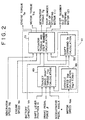
- FIG. 2 a control block diagram
- FIG. 3 a target drive shaft torque characteristic
- FIG. 4 a shift command characteristic.
- a power train control unit 41 of Fig. 1 are input an accelerator pedal angle ⁇ , a brake pedal force ⁇ , a shift lever position Ii, a battery capacity Vb, the speed Nm of the motor 29 detected by a motor speed detector 42, the engine speed Ne detected by an engine speed detector 43, and the generator speed Ng detected by a generator speed detector 44.
- torque of the engine 1 is calculated, and transmitted to an engine control unit 45 by LAN as communication means.
- an opening degree of a throttle valve for achieving the engine torque, the fuel flow rate and the ignition timing are calculated, and their respective actuators are controlled. Further, in the power train control unit 41, the torques of the motor 29 and the generator 15, and the number of steps of the stepping motor (1) 13 and the stepping motor (2) 28 are calculated, and transmitted to the motor control unit 46 by LAN so that the actuators therefor are controlled.
- the motor control unit 46 allows to charge electric power obtained from the generator 15 in a battery 47 and supply power from the battery 47 to drive the motor 29 and the like.
- the vehicle speed Vsp is calculated by the function f from the motor speed Nm in the process 48.
- the target drive shaft torque Ttar intended by an operator is calculated from the vehicle speed Vsp, the accelerator pedal angle ⁇ , the brake pedal force ⁇ , and the shift lever position Ii.
- a shift command Ss is calculated from the target drive shaft torque Ttar and the vehicle speed Vsp to select the gear 3 for low speed or the gear 6 for high speed.
- torques of the actuators (an engine torque Te, a motor torque Tm and a generator torque Tg), a step number Sn1 of the stepping motor (1), and a step number Sn2 of the stepping motor (2) are calculated from the target drive shaft torque Ttar, the vehicle speed Vsp, the battery capacity Vb, the engine speed Ne and the generator speed Ng, and output.
- the axis of abscissa indicates the vehicle speed Vsp
- the axis of ordinate indicates the target drive shaft torque Ttar.
- a portion above a point of intersection of the two axes represents that the drive torque is positive, while a portion below represents that the drive torque is negative.
- a portion on the right hand of the point of intersection represents a forward travel, while a portion on the left hand represents a backward travel.
- the solid line indicates the accelerator pedal angle ⁇ (%), and the diagonal line indicates the brake pedal force ⁇ .
- the larger % of the accelerator pedal angle a the larger the target drive shaft torque Ttar because an operator demands a great acceleration feeling. In case of the backward travel, since the vehicle speed need not be increased, the target drive shaft torque is small.
- the brake pedal force ⁇ shows a high value in the lower part in FIG. 3, it indicates that an operator demands a great deceleration.
- the target drive torque is positive to generate the torque of the motor 29 so as to simulate the generation of the maximum torque at stall speed using a torque converter.
- the mesh region is a motor driving region
- the diagonal region is an engine driving region.
- FIG. 4 shows the shift command Ss characteristics of a shift mechanism using the dog clutch for making the operation region of the engine 1 and the motor 29 highly efficient.
- the shift command Ss is determined by the vehicle speed Vsp and the target drive shaft torque Ttar.
- the value in which the engine 1 and the motor 29 has the maximum efficiency in the overall operation region is obtained in advance by the experiment or simulation and stored in memory means (not shown) within the power train control unit 41.
- FIG. 5 shows the system constitution in a series mode
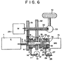
- FIG. 6 shows the system constitution in a parallel mode at the time of low speed
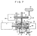
- FIG. 7 shows the system constitution in a parallel mode at the time of high speed
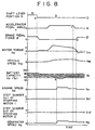
- FIG. 8 is a time chart at the time of operation in a series mode
- FIG. 9 is a time chart at the time of operation in a parallel mode
- FIG. 10 is a time chart at the time of switching a shift mechanism.
- the series mode termed herein is an operation in which the generator 15 is driven by the engine 1, and the motor 29 is driven by power charged in the battery 47 to run the vehicle.
- the stepping motor (1) 13 is rotated rightward, the rack 11 is moved leftward, and the sleeve 8 is set to a neutral position.
- the stepping motor (2) 28 is rotated rightward, the rack 26 is moved leftward, and the sleeve 23 is set to the meshing gear 17 provided on the output shaft 2 of the engine 1.
- the engine 1 drives only the generator 15 to enable charging the battery 47.
- the generator 15 can be operated also as a motor, and the engine 1 is started by the generator 15.
- the axis of abscissa indicates the time
- the axis of ordinate indicates the shift lever position Ii, the accelerator pedal angle ⁇ , the brake pedal force ⁇ , the motor torque Tm, the vehicle speed Vsp, the battery capacity Vb, the engine speed Ne, step number Sn1 of the stepping motor (1), step number Sn2 of the stepping motor (2), and the generator speed Ng.
- the running conditions are the case where the vehicle starts from its stop state, and the accelerator pedal angle ⁇ is changed during running. An operator applies a brake in the state where the shift lever position is N (neutral), and therefore, the vehicle stops.
- the battery capacity is also in a state requiring no charge.
- the generator 15 is used as a motor to start the engine 1. Thereafter, the generator 15 is used as a generator and charging is executed by the torque of the engine 1. In the case where an operator sets the accelerator pedal angle ⁇ to 0% (c) and applies a brake (d), the revival is executed by the motor 29 to charge the battery.
- the parallel mode termed is an operation in which the generator 15 is driven by the engine 1, the motor 29 is driven by power charged in the battery 47 to run the vehicle and at the same time the torque of the engine 1 is applied to drive the vehicle.
- the stepping motor (1) 13 is rotated rightward, the rack 11 is moved leftward, and the sleeve 8 is set to the meshing gear 3 provided on the gear 4 on the engine side for low speed.
- the stepping motor (2) 28 is rotated rightward, the rack 26 is moved rightward, and the sleeve 23 is set to the meshing gear 21 mounted on the output shaft 16 of the generator 15.
- the torque of the engine 1 is transmitted to the tire 10 through the gear 4 on the engine side for low speed and the gear 31 on the motor side for low speed.
- the axis of abscissa indicates the time
- the axis of ordinate indicates the shift lever position Ii, the accelerator pedal angle ⁇ , the brake pedal force ⁇ , the motor torque Tm, the engine torque Te, the drive shaft torque To, the vehicle speed Vsp, the engine speed Ne, step number Sn1 of the stepping motor (1), step number Sn2 of the stepping motor (2), and the generator speed Ng.
- the running conditions are the case where the accelerator pedal angle ⁇ is changed during running at constant vehicle speed.
- the accelerator pedal angle ⁇ is greatly applied (e)
- the target drive shaft torque Ttar increases. Therefore, it is necessary to increase the motor torque Tm and output the engine torque Te.
- the engine 1 and the generator 15 are integrated, the output shaft 2 of the engine 1 is adjusted to the speed (speed of the motor 29) of the gear 4 on the engine side for low speed by the generator 15, the stepping motor (2) is rotated to the positive side (right rotation: movement leftward of the rack 11) at f, and the sleeve 8 is meshed with the meshing gear 3 of the gear 4 on the engine side for low speed.
- the parallel mode is enabled by addition of the smooth engine torque Te.
- FIG. 7 shows a parallel mode at the time of high speed.
- the stepping motor (1) 13 is rotated leftward, the rack 11 is moved rightward, and the sleeve 8 is set to the meshing gear 5 provided on the gear 6 on the engine side for high speed.
- the stepping motor (2) 28 is rotated leftward, the rack 26 is moved rightward, and the sleeve 23 is disengaged from the output shaft 2 of the engine 1.
- the torque of the engine 1 is transmitted to the tire 10 through the gear 6 on the engine side for high speed and the gear 32 on the motor side for high speed.
- the generator 15 is disengaged from the output shaft 2 and a torque corresponding to an inertia torque of the generator can be reduced.
- the axis of abscissa indicates the time
- the axis of ordinate indicates the shift command Ss, the accelerator pedal angle a, the brake pedal force ⁇ , the motor torque Tm, the engine torque Te, the generator torque Tg, the drive shaft torque To, the vehicle speed Vsp, the engine speed Ne, step number Sn1 of the stepping motor (1), and step number Sn2 of the stepping motor (2).
- the running conditions are the case where the shift command Ss is changed during running at constant accelerator pedal angle a.
- the shift command Ss has been changed (h)
- the shift is made by movement of the sleeve 8. Therefore, the engine torque Te and the generator torque Tg are increased temporaly, the step number Sn1 of the stepping motor (1) is set to negative, and the shift of the gear 6 on the engine side for high speed is executed. This is because of the fact that when torque occurs at the sleeve 8, the movement of the sleeve 8 is difficult. Since at the time of shift, the torque from the engine 1 lowers, the torque Tm of the motor 29 is increased disregarding the fuel cost to prevent the torque from being lowered. The frequency of increase in the motor torque Tm is merely during the shift, not leading to an increase in fuel cost.
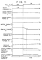
- FIG. 11 is a time chart when an actuator is in trouble.
- the axis of abscissa indicates the time
- the axis of ordinate indicates a fail-safe flag Ff
- the shift command Ss the accelerator pedal angle ⁇ , the brake pedal force ⁇ , the motor torque Tm, the engine torque Te, the generator torque Tg, the drive shaft torque To, the vehicle speed Vsp, step number Sn1 of the stepping motor (1), and step number Sn2 of the stepping motor (2).
- the fail conditions are the case where the stepping motor (1) is not actuated, and the gear 4 on the engine side for low speed is fixed.
- FIG. 12 shows an example in which a wobble motor is applied to a linear actuator.
- a linear actuator shown in FIG. 12 was applied.
- the sleeve 8 is provided with a lever 52 for movement of the sleeve 8.
- a member 54 for supporting a ball 53 is mounted on the lever 52, the ball being constituted so as not to transmit rotation of a screw 56 to the lever 52.
- the screw 56 is rotated by power supplied to a stator 55 to effect linear motion.
- a motor comprising the screw 56 and the stator 56 is called a wobble motor.
- a power transmission apparatus for an automobile comprising a generator driven by an output of the engine, a battery charged by generation output of the generator, and a motor driven by discharge output of the battery, wherein a clutch mechanism is provided between the output shaft of the engine and an output shaft of the generator whereby an occurrence of inertial torque of the generator can be suppressed.
Landscapes
- Engineering & Computer Science (AREA)
- Mechanical Engineering (AREA)
- Transportation (AREA)
- Chemical & Material Sciences (AREA)
- Combustion & Propulsion (AREA)
- Automation & Control Theory (AREA)
- Power Engineering (AREA)
- General Engineering & Computer Science (AREA)
- Sustainable Development (AREA)
- Sustainable Energy (AREA)
- Life Sciences & Earth Sciences (AREA)
- Electric Propulsion And Braking For Vehicles (AREA)
- Hybrid Electric Vehicles (AREA)
- Arrangement Of Transmissions (AREA)
- Control Of Vehicle Engines Or Engines For Specific Uses (AREA)
Claims (9)
- Kraftübertragungsvorrichtung für ein Kraftfahrzeug, mit
einem Mechanismus, in dem eine Rotationskraft eines Verbrennungsmotors ( 1 ) und eine Rotationskraft eines elektrischen Motors (29) synthetisiert oder selektiv geschaltet werden, um ein Antriebsrad (10) anzutreiben, wobei die Rotationskraft des Verbrennungsmotors (1) oder des Antriebsrads (10) von einem Generator (15) in elektrische Energie umgewandelt wird und die umgewandelte elektrische Energie an den elektrischen Motor (29) geliefert wird, wobei die Kraftübertragungsvorrichtung aufweist:
einen Mechanismus zum Trennen des Generators (15) von einem aus dem Verbrennungsmotor (1) und dem Antriebsrad (10) bestehenden Rotationskraftübertragungssystem;
wobei das aus dem Verbrennungsmotor ( 1 ) und dem Antriebsrad (10) bestehende Rotationskraftübertragungssystem aufweist einen Mechanismus (7, 8, 11, 13, 14) zum Umschalten eines ersten Übertragungssystems (6, 32) mit einem ersten Drehzahlverhältnis zwischen dem Verbrennungsmotor (1) und dem Rad (10) in ein zweites Übertragungssystem (4, 31) oder aus einem zweiten Übertragungssystem (4, 31) mit einem zweiten Drehzahlverhältnis;
dadurch gekennzeichnet, dass
die Vorrichtung weiter eine Kraftübertragungs-Steuereinheit (41) und eine Motor-Steuereinheit (46) aufweist, die derart eingerichtet sind, dass
in dem Fall, in dem eine Rotation von dem ersten Übertragungssystem (6, 32) übertragen wird, das aus dem Verbrennungsmotor (1) und dem Antriebsrad (10) bestehende Rotationskraftübertragungssystem von dem Generator (15) getrennt ist; und
in dem Fall, in dem eine Rotation von dem zweiten Übertragungssystem (4, 31) übertragen wird, das aus dem Verbrennungsmotor (1) und dem Antriebsrad (10) bestehende Rotationskraftübertragungssystem mit dem Generator (15) verbunden ist. - Kraftübertragungsvorrichtung gemäß Anspruch 1,
dadurch gekennzeichnet, dass
das zweite Übertragungssystem (4, 31) ferner einen neutralen Zustand zum Trennen des Verbrennungsmotors (1) und des Antriebsrads (10) des Rotationskraftübertragungssystem voneinander aufweist,
wobei nicht nur in dem Fall, wenn eine Rotation von dem zweiten Übertragungssystem (4, 31) übertragen wird, sondern auch wenn sich die Rotation in dem neutralen Zustand befindet, das aus dem Verbrennungsmotor (1) und dem Antriebsrad (10) bestehende Rotationskraftübertragungssystem mit dem Generator (15) verbunden ist. - Kraftübertragungsvorrichtung für ein Kraftfahrzeug gemäß Anspruch 1 oder 2, gekennzeichnet durch einen ersten Kupplungsmechanismus (23), der zwischen einer Abtriebswelle (2) des Verbrennungsmotors ( 1 ) und einer Abtriebswelle (16) des Generators (15) vorgesehen ist.
- Kraftübertragungsvorrichtung gemäß zumindest einem der vorhergehenden Ansprüche, gekennzeichnet dadurch, dass der Mechanismus zum Umschalten zwischen dem ersten Übertragungssystem (6, 32) und dem zweiten Übertragungssystem (4, 31) einen zweiten Kupplungsmechanismus (8) zum Drehzahl-Umschalten aufweist, der zwischen einer Abtriebswelle (2) des Verbrennungsmotors (1) und einer Abtriebswelle (30) des elektrischen Motors (29) vorgesehen ist.
- Kraftübertragungsvorrichtung gemäß Anspruch 4, dadurch gekennzeichnet, dass
der zweite Kupplungsmechanismus (8) eine Vorrichtung ist, die, wenn eingekuppelt oder ausgekuppelt, keine Energie zum Einkuppeln oder Auskuppeln erfordert. - Kraftübertragungsvorrichtung gemäß Anspruch 5, dadurch gekennzeichnet, dass
der Kupplungsmechanismus (8) eine Klauenkupplung ist. - Kraftübertragungsvorrichtung gemäß Anspruch 6 oder 7, gekennzeichnet durch ein lineares Stellglied zum Betätigen der Klauenkupplung.
- Kraftübertragungsvorrichtung gemäß zumindest einem der vorhergehenden Ansprüche, gekennzeichnet durch
Haltemittel zum Halten von dem Mechanismus zum Umschalten zwischen dem ersten Übertragungssystem (6, 32) und dem zweiten Übertragungssystem (4, 31) und/ oder der ersten Kupplung (23) in einem unbeweglichen Zustand nur mit einer mechanischen Gegenkraft. - Kraftübertragungsvorrichtung für ein Kraftfahrzeug gemäß Anspruch 9, dadurch gekennzeichnet, dass
das Mittel zum Halten des Mechanismus in einem unbeweglichen Zustand ein Wobbel-Motor (55, 56) ist.
Applications Claiming Priority (2)
| Application Number | Priority Date | Filing Date | Title |
|---|---|---|---|
| JP11817598A JP3336951B2 (ja) | 1998-04-28 | 1998-04-28 | 自動車の動力伝達装置 |
| JP11817598 | 1998-04-28 |
Publications (3)
| Publication Number | Publication Date |
|---|---|
| EP0953467A2 EP0953467A2 (de) | 1999-11-03 |
| EP0953467A3 EP0953467A3 (de) | 2001-03-21 |
| EP0953467B1 true EP0953467B1 (de) | 2004-12-22 |
Family
ID=14729994
Family Applications (1)
| Application Number | Title | Priority Date | Filing Date |
|---|---|---|---|
| EP99107435A Expired - Lifetime EP0953467B1 (de) | 1998-04-28 | 1999-04-27 | Vorrichtung zur Kraftübertragung für ein Kraftfahrzeug |
Country Status (5)
| Country | Link |
|---|---|
| US (4) | US6142907A (de) |
| EP (1) | EP0953467B1 (de) |
| JP (1) | JP3336951B2 (de) |
| KR (1) | KR19990083546A (de) |
| DE (1) | DE69922731T2 (de) |
Families Citing this family (121)
| Publication number | Priority date | Publication date | Assignee | Title |
|---|---|---|---|---|
| DE19814402C2 (de) * | 1998-03-31 | 2000-03-23 | Isad Electronic Sys Gmbh & Co | Antriebssystem für ein Kraftfahrzeug sowie Verfahren zum Betreiben desselben |
| JP3668830B2 (ja) * | 1998-08-28 | 2005-07-06 | トヨタ自動車株式会社 | 動力伝達装置およびこれを用いたハイブリット車輌 |
| GB2348630B (en) * | 1998-09-09 | 2002-12-04 | Luk Lamellen & Kupplungsbau | Drive train |
| US6554088B2 (en) | 1998-09-14 | 2003-04-29 | Paice Corporation | Hybrid vehicles |
| WO2000032433A1 (en) * | 1998-12-01 | 2000-06-08 | Hitachi, Ltd. | Drive device and vehicle |
| JP3449277B2 (ja) * | 1999-02-05 | 2003-09-22 | 株式会社日立製作所 | ハイブリッド車両およびその制御装置 |
| JP3286619B2 (ja) * | 1999-04-06 | 2002-05-27 | 株式会社日立製作所 | 自動車の動力伝達装置 |
| JP2000301959A (ja) * | 1999-04-21 | 2000-10-31 | Hitachi Ltd | 自動車の動力伝達装置 |
| JP3574997B2 (ja) * | 1999-06-11 | 2004-10-06 | 本田技研工業株式会社 | ブレーキ力制御装置 |
| DE19931311C2 (de) * | 1999-07-07 | 2003-04-17 | Bernd-Robert Hoehn | Antriebsanordnung |
| JP3377040B2 (ja) * | 1999-10-08 | 2003-02-17 | トヨタ自動車株式会社 | ハイブリッド車両の制御装置 |
| US6656082B1 (en) * | 1999-10-12 | 2003-12-02 | Toyota Jidosha Kabushiki Kaisha | Hybrid vehicle and method of controlling the same |
| DE19953495C2 (de) * | 1999-11-06 | 2002-10-24 | Daimler Chrysler Ag | Antriebseinheit für ein Kraftfahrzeug |
| JP3909644B2 (ja) * | 1999-12-27 | 2007-04-25 | アイシン・エィ・ダブリュ株式会社 | ハイブリッド駆動装置 |
| US7185722B1 (en) * | 2000-02-04 | 2007-03-06 | Hitachi, Ltd. | Power transmission apparatus of motor vehicles |
| JP3294230B2 (ja) * | 2000-02-22 | 2002-06-24 | 株式会社日立製作所 | 自動車用制御装置,自動車の制御方法,変速機 |
| JP3677733B2 (ja) * | 2000-04-06 | 2005-08-03 | ジヤトコ株式会社 | パラレルハイブリッド車両 |
| US6691807B1 (en) * | 2000-04-11 | 2004-02-17 | Ford Global Technologies Llc | Hybrid electric vehicle with variable displacement engine |
| JP3293613B2 (ja) * | 2000-06-23 | 2002-06-17 | 株式会社日立製作所 | 自動車用制御装置,自動車の制御方法,変速機 |
| DE10052231A1 (de) * | 2000-10-21 | 2002-05-02 | Daimler Chrysler Ag | Fahrzeug |
| JP3573202B2 (ja) * | 2000-11-06 | 2004-10-06 | 三菱自動車工業株式会社 | ハイブリッド車両のトルク制御装置 |
| US6890283B2 (en) * | 2000-11-13 | 2005-05-10 | Honda Giken Kogyo Kabushiki Kaisha | Control apparatus for controlling transmission of hybrid vehicle |
| JP4108265B2 (ja) * | 2000-11-22 | 2008-06-25 | 本田技研工業株式会社 | 車両用クラッチの接続状態判定装置およびこれを用いた変速制御装置 |
| DE10058020B4 (de) * | 2000-11-23 | 2013-09-12 | Burani Consulting Limited Liability Company | Kraftfahrzeugantrieb |
| JP2002199506A (ja) * | 2000-12-22 | 2002-07-12 | Mazda Motor Corp | ハイブリッド駆動装置 |
| JP3815220B2 (ja) * | 2000-12-27 | 2006-08-30 | アイシン・エィ・ダブリュ株式会社 | ハイブリッド型車両及びその制御方法 |
| US6889132B2 (en) * | 2001-02-01 | 2005-05-03 | Ford Global Technologies, Llc | Vehicle drive control for 4×4 mode |
| US7086977B2 (en) * | 2001-05-03 | 2006-08-08 | Ford Global Technologies, Llc | Transmission arrangements for hybrid electric vehicles |
| EP1270301A3 (de) * | 2001-06-19 | 2007-02-21 | Hitachi, Ltd. | Kraftfahrzeuggetriebe mit Schaltungen ohne Drehmoment Unterbrechung |
| JP4806873B2 (ja) * | 2001-08-30 | 2011-11-02 | トヨタ自動車株式会社 | 車両用パワートレーンの構造 |
| JP3852321B2 (ja) * | 2001-10-22 | 2006-11-29 | トヨタ自動車株式会社 | クランキング支持トルク増大手段付きhv駆動構造および方法 |
| KR100461078B1 (ko) * | 2001-11-28 | 2004-12-09 | 현대자동차주식회사 | 자동 트랜스퍼 쉬프팅 장치 |
| US6629026B1 (en) * | 2002-04-12 | 2003-09-30 | Ford Motor Company | Hybrid electric vehicle with motor torque fill in |
| JP2004092634A (ja) * | 2002-07-12 | 2004-03-25 | Kokusan Denki Co Ltd | 発電機搭載内燃機関駆動車両 |
| US7300381B2 (en) * | 2002-11-30 | 2007-11-27 | Ford Global Technologies, Llc | Method for managing engine torque during a gear shift in an automatic shift manual transmission |
| CN1291855C (zh) * | 2002-12-08 | 2006-12-27 | 中国第一汽车集团公司 | 双电机混合动力汽车动力系统 |
| JP2004222435A (ja) * | 2003-01-16 | 2004-08-05 | Fuji Heavy Ind Ltd | 電気自動車の駆動装置 |
| US7196430B2 (en) * | 2003-02-12 | 2007-03-27 | Tai-Her Yang | Partial-powered series hybrid driving system |
| US7315090B2 (en) * | 2003-02-12 | 2008-01-01 | Tai-Her Yang | Series-parallel dual power hybrid driving system |
| US20040155468A1 (en) * | 2003-02-12 | 2004-08-12 | Tai-Her Yang | Series and parallel combined dual power drive system |
| US6991053B2 (en) * | 2003-02-27 | 2006-01-31 | Ford Global Technologies, Llc | Closed-loop power control for hybrid electric vehicles |
| US6998727B2 (en) * | 2003-03-10 | 2006-02-14 | The United States Of America As Represented By The Administrator Of The Environmental Protection Agency | Methods of operating a parallel hybrid vehicle having an internal combustion engine and a secondary power source |
| JP3885768B2 (ja) * | 2003-05-20 | 2007-02-28 | トヨタ自動車株式会社 | ハイブリッド車およびその制御方法 |
| JP4013905B2 (ja) * | 2003-05-21 | 2007-11-28 | トヨタ自動車株式会社 | 動力出力装置およびその制御方法並びに自動車 |
| US6876098B1 (en) | 2003-09-25 | 2005-04-05 | The United States Of America As Represented By The Administrator Of The Environmental Protection Agency | Methods of operating a series hybrid vehicle |
| JP2005130564A (ja) * | 2003-10-22 | 2005-05-19 | Fuji Heavy Ind Ltd | ハイブリッド車両の制御装置 |
| US7125362B2 (en) | 2004-01-23 | 2006-10-24 | Eaton Corporation | Hybrid powertrain system including smooth shifting automated transmission |
| US20050230975A1 (en) * | 2004-04-19 | 2005-10-20 | Tai-Her Yang | Series and parallel combined dual power drive system |
| FR2868995B1 (fr) * | 2004-04-20 | 2007-06-29 | Renault Sas | Transmission infiniment variable a derivation de puissance a deux modes de fonctionnement pour vehicule automobile |
| FR2869571B1 (fr) * | 2004-04-29 | 2007-06-22 | Renault Sas | Groupe motopropulseur hybride et son procede de fonctionnement |
| JP2005333690A (ja) * | 2004-05-18 | 2005-12-02 | Denso Corp | ハイブリッド車の制御装置 |
| US7285869B2 (en) * | 2004-07-29 | 2007-10-23 | Ford Global Technologies, Llc | Method for estimating engine power in a hybrid electric vehicle powertrain |
| FR2875280B1 (fr) * | 2004-09-15 | 2008-02-15 | Peugeot Citroen Automobiles Sa | Dispositif de commutation pour vehicule automobile et utilisation de ce dispositif |
| JP2007001493A (ja) * | 2005-06-27 | 2007-01-11 | Nissan Motor Co Ltd | ハイブリッド車両の制御装置 |
| DE102006055448A1 (de) * | 2006-02-13 | 2007-09-06 | Volkswagen Ag | Verfahren zum Abkoppeln wenigstens einer Momentenquelle, Antrieb für ein Kraftfahrzeug, Steuerungssystem und Kraftfahrzeug |
| FR2899548B1 (fr) * | 2006-04-05 | 2009-04-17 | Peugeot Citroen Automobiles Sa | Procede de transmission de puissance |
| JP4228007B2 (ja) * | 2006-06-23 | 2009-02-25 | トヨタ自動車株式会社 | 動力出力装置およびこれを搭載する車両 |
| US7547981B2 (en) * | 2007-02-09 | 2009-06-16 | Caterpillar Inc. | Machine having electrical power system and method |
| DE102007016218B4 (de) * | 2007-04-04 | 2016-06-09 | Audi Ag | Hybrid-Antriebsvorrichtung für Kraftfahrzeuge |
| US7942781B2 (en) * | 2007-10-12 | 2011-05-17 | Means Industries, Inc. | High-efficiency vehicular transmission |
| JP5246466B2 (ja) * | 2007-10-19 | 2013-07-24 | アイシン・エィ・ダブリュ株式会社 | ハイブリッド駆動装置 |
| CN101450609B (zh) * | 2007-11-30 | 2012-09-05 | 比亚迪股份有限公司 | 混合动力驱动系统及其驱动方法 |
| CN101450608B (zh) * | 2007-12-07 | 2012-09-05 | 比亚迪股份有限公司 | 混合动力车的停车发电机构及其控制方法 |
| US8358046B2 (en) * | 2007-12-28 | 2013-01-22 | Platon Mihai C | Hybrid electric power system with distributed segmented generator/motor |
| DE102008000576A1 (de) * | 2008-03-10 | 2009-09-17 | Robert Bosch Gmbh | Verfahren und Vorrichtung zum Betreiben eines Fahrzeuges mit Hybridantrieb |
| US8500589B2 (en) | 2008-08-07 | 2013-08-06 | Ford Global Technologies, Llc | Hybrid electric vehicle powertrain with an enhanced all-electric drive mode |
| US20110000721A1 (en) * | 2009-07-02 | 2011-01-06 | Thermal Motor Innovations, Llc | Hybrid parallel load assist systems and methods |
| FR2953772B1 (fr) * | 2009-12-15 | 2012-01-06 | Continental Automotive France | Procede de pilotage d'un dispositif de motorisation de vehicule hybride, et dispositif associe |
| TWI408878B (zh) * | 2010-07-14 | 2013-09-11 | Kwang Yang Motor Co | Vehicle power generation device |
| US9435387B2 (en) | 2010-12-10 | 2016-09-06 | Means Industries, Inc. | Device and apparatus for controlling the operating mode of a coupling assembly, coupling and control assembly and electric motor disconnect and pass through assemblies |
| US9377061B2 (en) | 2010-12-10 | 2016-06-28 | Means Industries, Inc. | Electromagnetic system for controlling the operating mode of an overrunning coupling assembly and overrunning coupling and control assembly including the system |
| US10677296B2 (en) | 2010-12-10 | 2020-06-09 | Means Industries, Inc. | Electronic, high-efficiency vehicular transmission, overrunning, non-friction coupling and control assembly and switchable linear actuator device for use therein |
| US9874252B2 (en) | 2010-12-10 | 2018-01-23 | Means Industries, Inc. | Electronic, high-efficiency vehicular transmission, overrunning, non-friction coupling and control assembly and switchable linear actuator device for use therein |
| US8387729B2 (en) * | 2011-03-10 | 2013-03-05 | Caterpillar Inc. | Machine having electrical power system and centered drive coupling for same |
| JP2012210903A (ja) * | 2011-03-31 | 2012-11-01 | Toyota Central R&D Labs Inc | 動力伝達装置 |
| WO2012137297A1 (ja) * | 2011-04-05 | 2012-10-11 | トヨタ自動車株式会社 | 車両および車両用制御方法 |
| JP5855843B2 (ja) * | 2011-04-20 | 2016-02-09 | Gknドライブラインジャパン株式会社 | 駆動装置 |
| CN102555769B (zh) * | 2012-03-12 | 2014-12-10 | 重庆大学 | 一种混联式双电机多工作模式混合动力驱动总成 |
| WO2013145333A1 (en) * | 2012-03-30 | 2013-10-03 | Honda Motor Co., Ltd. | Internal combustion engine control apparatus and internal combustion engine control method |
| WO2014011230A1 (en) * | 2012-07-09 | 2014-01-16 | Eaton Corporation | Clutch system |
| JP2014149020A (ja) * | 2013-01-31 | 2014-08-21 | Aisin Seiki Co Ltd | 自動変速機用ドグクラッチ制御装置 |
| US10533618B2 (en) | 2013-09-26 | 2020-01-14 | Means Industries, Inc. | Overrunning, non-friction coupling and control assembly, engageable coupling assembly and locking member for use in the assemblies |
| US9145133B2 (en) * | 2013-11-08 | 2015-09-29 | Ford Global Technologies, Llc | Method and system for selecting an engine operating point for a hybrid vehicle |
| US10619681B2 (en) | 2014-09-16 | 2020-04-14 | Means Industries, Inc. | Overrunning, non-friction coupling and control assemblies and switchable linear actuator device and reciprocating electromechanical apparatus for use therein |
| US9574638B2 (en) * | 2014-09-23 | 2017-02-21 | Hyundai Motor Company | Transmission for vehicle |
| CN105599586A (zh) * | 2016-02-05 | 2016-05-25 | 海博瑞德(北京)汽车技术有限公司 | 一种在变速箱输入轴增加驱动电机的bsg混合动力系统 |
| CN105599587A (zh) * | 2016-02-05 | 2016-05-25 | 海博瑞德(北京)汽车技术有限公司 | 一种配置双变速的bsg混合动力系统 |
| FR3048047B1 (fr) * | 2016-02-19 | 2018-03-09 | Renault S.A.S | Procede de controle du decrabotage d'un baladeur |
| US10414263B2 (en) | 2016-04-08 | 2019-09-17 | Hyundai Motor Company | Transmission for vehicle |
| DE102016220117A1 (de) * | 2016-10-14 | 2018-04-19 | Continental Automotive Gmbh | Low Cost Hybrid-Antriebsstrangarchitektur |
| FR3059289B1 (fr) * | 2016-11-25 | 2018-11-09 | Renault S.A.S | Procede de commande d'un groupe motopropulseur hybride automobile muni d'une boite de vitesse |
| JP2020506336A (ja) | 2017-02-02 | 2020-02-27 | ミーンズ インダストリーズ,インク. | オーバーランニング非摩擦連結制御アセンブリ、切替可能な線形アクチュエータ機器およびこれに使用する往復運動電気機械装置 |
| US11035423B2 (en) | 2017-02-02 | 2021-06-15 | Means Industries, Inc. | Non-friction coupling and control assembly, engageable coupling assembly and locking member for use in the assemblies |
| DE102017203335A1 (de) * | 2017-03-01 | 2018-09-06 | Audi Ag | Antriebseinrichtung für ein Kraftfahrzeug |
| US10590999B2 (en) | 2017-06-01 | 2020-03-17 | Means Industries, Inc. | Overrunning, non-friction, radial coupling and control assembly and switchable linear actuator device for use in the assembly |
| CN109552024B (zh) * | 2017-09-25 | 2023-12-15 | 宇通客车股份有限公司 | 一种车辆动力传动系统及其变速机构 |
| CN108128137A (zh) * | 2017-12-29 | 2018-06-08 | 苏州凯博易控驱动技术有限公司 | 变速系统、变速方法及相应的车辆 |
| DE212019000176U1 (de) | 2018-01-29 | 2020-08-31 | Dana Automotive Systems Group, Llc | Abkoppeleinrichtung für zusammengesetztes Leerlaufgetriebe und die damit hergestellte Antriebsachse |
| JP6965792B2 (ja) * | 2018-02-28 | 2021-11-10 | トヨタ自動車株式会社 | 車両用駆動装置 |
| CN113412205B (zh) | 2019-02-08 | 2024-08-20 | 敏思工业公司 | 非摩擦式耦合和控制组件、可接合的耦合组件和组件中使用的锁定构件 |
| US11472308B2 (en) | 2019-04-05 | 2022-10-18 | Oshkosh Corporation | Electric concrete vehicle systems and methods |
| WO2021064437A1 (ja) * | 2019-10-01 | 2021-04-08 | 日産自動車株式会社 | 車両用の動力伝達方法及び車両用の動力伝達装置 |
| WO2021072087A1 (en) * | 2019-10-11 | 2021-04-15 | Oshkosh Corporation | Vehicle with accessory drive |
| US11215245B2 (en) | 2019-12-03 | 2022-01-04 | Means Industries, Inc. | Coupling and control assembly including controllable coupling assembly having speed sensor and methods of controlling the controllable coupling assembly using information from the speed sensor for park/hill-hold operations |
| US11286996B2 (en) | 2020-02-12 | 2022-03-29 | Means Industries, Inc. | Electro-dynamic coupling and control assembly and switchable linear actuator device for use therein |
| US11846085B2 (en) | 2020-02-17 | 2023-12-19 | Deere & Company | Energy management system for a hybrid vehicle with an electrically powered hydraulic system |
| JP6975277B2 (ja) * | 2020-02-28 | 2021-12-01 | 本田技研工業株式会社 | 車両の制御装置 |
| US11542992B2 (en) | 2020-03-31 | 2023-01-03 | Means Industries, Inc. | Coupling and control assembly including a non-contact, linear inductive position sensor |
| US11874142B2 (en) | 2020-03-31 | 2024-01-16 | Means Industries, Inc. | Coupling and control assembly including a position sensor |
| DE102021107969B4 (de) | 2020-03-31 | 2025-02-20 | Means Industries, Inc. | Kupplungs- und steuereinheit mit einem wegsensor |
| DE102021104228A1 (de) | 2020-03-31 | 2021-09-30 | Means Industries, Inc. | Kupplung und Steuerungsanordnung mit einem berührungslosen, linearen induktiven Positionssensor |
| CN111559257B (zh) * | 2020-05-21 | 2021-08-31 | 河南科技大学 | 增程式混合动力汽车及其参数匹配方法 |
| CN111993880A (zh) * | 2020-08-31 | 2020-11-27 | 中国第一汽车股份有限公司 | 一种混合动力系统 |
| US11613246B2 (en) * | 2021-01-21 | 2023-03-28 | Deere & Company | Power control system with engine throttle shift function |
| US11628822B2 (en) | 2021-02-09 | 2023-04-18 | Deere & Company | Power control system with stall prevention clutch modulation function |
| FR3120102B1 (fr) * | 2021-02-22 | 2023-02-24 | Valeo Embrayages | Module pour un système de synchronisation et d’entraînement d’un arbre intermédiaire d’une boîte de transmission |
| US11820361B2 (en) | 2021-11-30 | 2023-11-21 | Deere & Company | Transmission assembly with electrical machine unit for improved shift quality |
| US11585412B1 (en) | 2021-12-22 | 2023-02-21 | Deere & Company | Electronically-variable, dual-path power shift transmission for work vehicles |
| US11607948B1 (en) | 2021-12-22 | 2023-03-21 | Deere & Company | Electronically-variable power shift transmission for work vehicles |
| US11913528B1 (en) | 2022-10-28 | 2024-02-27 | Deere & Company | Multi-mode continuously variable transmission assembly with drop set arrangement |
| WO2025182665A1 (ja) * | 2024-03-01 | 2025-09-04 | 三菱自動車工業株式会社 | モータユニット |
Family Cites Families (28)
| Publication number | Priority date | Publication date | Assignee | Title |
|---|---|---|---|---|
| US1992210A (en) * | 1933-05-05 | 1935-02-26 | Frank R Higley | Electromechanical drive |
| US2790337A (en) * | 1953-08-29 | 1957-04-30 | Fischer Ag Georg | Infinitely variable two-motor drive |
| US2924991A (en) * | 1955-04-14 | 1960-02-16 | Lowell Taylor E | Speed-torque converter |
| US3205965A (en) * | 1961-08-04 | 1965-09-14 | Linde Eismasch Ag | Motor vehicle |
| US3478851A (en) * | 1967-08-09 | 1969-11-18 | Smyth Robert Ralston | Automotive transmission |
| US3580107A (en) * | 1968-10-21 | 1971-05-25 | Urs Systems Corp | Transmission |
| JPS5030223A (de) * | 1973-07-20 | 1975-03-26 | ||
| JPS55127221A (en) * | 1979-03-20 | 1980-10-01 | Daihatsu Motor Co Ltd | Driving system of vehicle |
| DE2943554A1 (de) * | 1979-10-27 | 1981-05-07 | Volkswagenwerk Ag | Hybrid-antrieb fuer ein fahrzeug, insbesondere kraftfahrzeug |
| US4588040A (en) * | 1983-12-22 | 1986-05-13 | Albright Jr Harold D | Hybrid power system for driving a motor vehicle |
| US4664217A (en) * | 1984-12-24 | 1987-05-12 | United Technologies Electro Systems, Inc. | Electric shift actuator for vehicle transfer case |
| US5251503A (en) * | 1991-09-12 | 1993-10-12 | General Motors Corporation | Electro-mechanical power controller for a gear shift mechanism |
| DE4202083C2 (de) * | 1992-01-25 | 1994-01-20 | Daimler Benz Ag | Hybridantrieb für ein Kraftfahrzeug |
| US5301764A (en) * | 1992-04-13 | 1994-04-12 | Gardner Conrad O | Hybrid motor vehicle having an electric motor and utilizing an internal combustion engine for fast charge during cruise mode off condition |
| GB2275309B (en) * | 1993-02-22 | 1997-10-29 | Yang Tai Her | Differential coupling and compounding system |
| DE4444545B4 (de) * | 1993-12-22 | 2004-05-27 | Volkswagen Ag | Antriebsstrang für ein Hybridfahrzeug |
| JP3291916B2 (ja) * | 1994-06-06 | 2002-06-17 | 株式会社エクォス・リサーチ | ハイブリッド型車両 |
| JP3052753B2 (ja) | 1994-09-29 | 2000-06-19 | トヨタ自動車株式会社 | シリーズパラレル複合電気自動車の制御装置 |
| US5562566A (en) * | 1994-10-03 | 1996-10-08 | Yang; Tai-Her | Distributed differential mixing combined power system |
| JP3045650B2 (ja) * | 1994-11-04 | 2000-05-29 | 株式会社エクォス・リサーチ | 車両用変速機 |
| US5603671A (en) * | 1995-08-08 | 1997-02-18 | General Motors Corporation | Three prime mover bus transmission |
| JP3584106B2 (ja) * | 1996-01-26 | 2004-11-04 | セイコーエプソン株式会社 | 電気自動車の駆動装置及びその制御方法 |
| US5735767A (en) * | 1996-10-21 | 1998-04-07 | New Venture Gear, Inc. | Add-on two-speed compounder |
| JP3376262B2 (ja) * | 1997-11-21 | 2003-02-10 | 日産ディーゼル工業株式会社 | ハイブリッド車両の非常駆動装置 |
| US6019698A (en) * | 1997-12-01 | 2000-02-01 | Daimlerchysler Corporation | Automated manual transmission shift sequence controller |
| US5943918A (en) * | 1997-12-01 | 1999-08-31 | Chrysler Corporation | Powertrain system for a hybrid electric vehicle |
| JP3341659B2 (ja) * | 1997-12-05 | 2002-11-05 | 日産自動車株式会社 | ハイブリッド車の制御装置 |
| US6427794B1 (en) * | 2001-09-17 | 2002-08-06 | Ford Global Technologies, Inc. | Adaptive demagnetization compensation for a motor in an electric or partially electric motor vehicle |
-
1998
- 1998-04-28 JP JP11817598A patent/JP3336951B2/ja not_active Expired - Fee Related
-
1999
- 1999-04-27 KR KR1019990015125A patent/KR19990083546A/ko not_active Withdrawn
- 1999-04-27 DE DE69922731T patent/DE69922731T2/de not_active Expired - Lifetime
- 1999-04-27 EP EP99107435A patent/EP0953467B1/de not_active Expired - Lifetime
- 1999-04-28 US US09/300,519 patent/US6142907A/en not_active Expired - Lifetime
-
2000
- 2000-05-24 US US09/576,819 patent/US6328670B1/en not_active Expired - Lifetime
-
2001
- 2001-04-27 US US09/842,980 patent/US6440036B2/en not_active Expired - Fee Related
-
2002
- 2002-03-27 US US10/106,059 patent/US6692405B2/en not_active Expired - Fee Related
Also Published As
| Publication number | Publication date |
|---|---|
| DE69922731T2 (de) | 2005-12-15 |
| KR19990083546A (ko) | 1999-11-25 |
| EP0953467A3 (de) | 2001-03-21 |
| US20010016536A1 (en) | 2001-08-23 |
| US6142907A (en) | 2000-11-07 |
| JP3336951B2 (ja) | 2002-10-21 |
| DE69922731D1 (de) | 2005-01-27 |
| US20020098941A1 (en) | 2002-07-25 |
| US6692405B2 (en) | 2004-02-17 |
| US6440036B2 (en) | 2002-08-27 |
| JPH11313404A (ja) | 1999-11-09 |
| EP0953467A2 (de) | 1999-11-03 |
| US6328670B1 (en) | 2001-12-11 |
Similar Documents
| Publication | Publication Date | Title |
|---|---|---|
| EP0953467B1 (de) | Vorrichtung zur Kraftübertragung für ein Kraftfahrzeug | |
| US7056260B2 (en) | Drive unit for vehicle | |
| US7819212B2 (en) | Power output apparatus and vehicle | |
| US8147366B2 (en) | Power output apparatus and vehicle | |
| US11052903B2 (en) | Hybrid vehicle drive system | |
| EP1441123B1 (de) | Anlassregelverfahren eines Verbrennungsmotors | |
| EP1776251B1 (de) | Start- und betriebssequenzen für fahrzeuge mit hybridmotor | |
| EP1297981B1 (de) | Hybridfahrzeug mit Planetengetriebe zur Verteilung der Antriebskraft | |
| US20100029436A1 (en) | Power output apparatus, hybrid vehicle provided with the same, and control method of power output apparatus | |
| US20110245033A1 (en) | Vehicular hybrid drive system | |
| US8496560B2 (en) | Starting control system for engines | |
| US20090134820A1 (en) | Drive unit for vehicle | |
| CN100431886C (zh) | 动力输出装置及其控制装置以及动力输出装置的控制方法 | |
| CN101036006A (zh) | 混合动力车辆及其控制方法 | |
| US11173915B2 (en) | Hybrid vehicle drive apparatus | |
| JPH11173174A (ja) | ハイブリット駆動装置における発進制御装置 | |
| US11447125B2 (en) | Vehicle control system | |
| JP3552708B2 (ja) | ハイブリッド自動車の動力伝達装置 | |
| JP3552707B2 (ja) | ハイブリッド自動車の動力伝達装置 | |
| US20200269831A1 (en) | Hybrid vehicle drive apparatus | |
| KR100778568B1 (ko) | 하이브리드 차량의 동력 전달계의 제어 방법 | |
| JP2008100544A (ja) | 動力出力装置およびこれを搭載する車両並びに動力出力装置の制御方法 |
Legal Events
| Date | Code | Title | Description |
|---|---|---|---|
| PUAI | Public reference made under article 153(3) epc to a published international application that has entered the european phase |
Free format text: ORIGINAL CODE: 0009012 |
|
| AK | Designated contracting states |
Kind code of ref document: A2 Designated state(s): DE FR GB IT |
|
| AX | Request for extension of the european patent |
Free format text: AL;LT;LV;MK;RO;SI |
|
| PUAL | Search report despatched |
Free format text: ORIGINAL CODE: 0009013 |
|
| AK | Designated contracting states |
Kind code of ref document: A3 Designated state(s): AT BE CH CY DE DK ES FI FR GB GR IE IT LI LU MC NL PT SE |
|
| AX | Request for extension of the european patent |
Free format text: AL;LT;LV;MK;RO;SI |
|
| 17P | Request for examination filed |
Effective date: 20010723 |
|
| AKX | Designation fees paid |
Free format text: DE FR GB IT |
|
| 17Q | First examination report despatched |
Effective date: 20020930 |
|
| GRAP | Despatch of communication of intention to grant a patent |
Free format text: ORIGINAL CODE: EPIDOSNIGR1 |
|
| GRAS | Grant fee paid |
Free format text: ORIGINAL CODE: EPIDOSNIGR3 |
|
| GRAA | (expected) grant |
Free format text: ORIGINAL CODE: 0009210 |
|
| AK | Designated contracting states |
Kind code of ref document: B1 Designated state(s): DE FR GB IT |
|
| REG | Reference to a national code |
Ref country code: GB Ref legal event code: FG4D |
|
| RAP2 | Party data changed (patent owner data changed or rights of a patent transferred) |
Owner name: HITACHI, LTD. |
|
| RAP2 | Party data changed (patent owner data changed or rights of a patent transferred) |
Owner name: HITACHI, LTD. |
|
| REF | Corresponds to: |
Ref document number: 69922731 Country of ref document: DE Date of ref document: 20050127 Kind code of ref document: P |
|
| ET | Fr: translation filed | ||
| PLBE | No opposition filed within time limit |
Free format text: ORIGINAL CODE: 0009261 |
|
| STAA | Information on the status of an ep patent application or granted ep patent |
Free format text: STATUS: NO OPPOSITION FILED WITHIN TIME LIMIT |
|
| 26N | No opposition filed |
Effective date: 20050923 |
|
| PGFP | Annual fee paid to national office [announced via postgrant information from national office to epo] |
Ref country code: GB Payment date: 20130424 Year of fee payment: 15 Ref country code: DE Payment date: 20130508 Year of fee payment: 15 |
|
| PGFP | Annual fee paid to national office [announced via postgrant information from national office to epo] |
Ref country code: IT Payment date: 20130420 Year of fee payment: 15 Ref country code: FR Payment date: 20130625 Year of fee payment: 15 |
|
| REG | Reference to a national code |
Ref country code: DE Ref legal event code: R119 Ref document number: 69922731 Country of ref document: DE |
|
| REG | Reference to a national code |
Ref country code: DE Ref legal event code: R079 Ref document number: 69922731 Country of ref document: DE Free format text: PREVIOUS MAIN CLASS: B60K0006040000 Ipc: B60K0006000000 |
|
| GBPC | Gb: european patent ceased through non-payment of renewal fee |
Effective date: 20140427 |
|
| REG | Reference to a national code |
Ref country code: FR Ref legal event code: ST Effective date: 20141231 |
|
| PG25 | Lapsed in a contracting state [announced via postgrant information from national office to epo] |
Ref country code: GB Free format text: LAPSE BECAUSE OF NON-PAYMENT OF DUE FEES Effective date: 20140427 Ref country code: DE Free format text: LAPSE BECAUSE OF NON-PAYMENT OF DUE FEES Effective date: 20141101 |
|
| REG | Reference to a national code |
Ref country code: DE Ref legal event code: R119 Ref document number: 69922731 Country of ref document: DE Effective date: 20141101 Ref country code: DE Ref legal event code: R079 Ref document number: 69922731 Country of ref document: DE Free format text: PREVIOUS MAIN CLASS: B60K0006040000 Ipc: B60K0006000000 Effective date: 20141223 |
|
| PG25 | Lapsed in a contracting state [announced via postgrant information from national office to epo] |
Ref country code: FR Free format text: LAPSE BECAUSE OF NON-PAYMENT OF DUE FEES Effective date: 20140430 |
|
| PG25 | Lapsed in a contracting state [announced via postgrant information from national office to epo] |
Ref country code: IT Free format text: LAPSE BECAUSE OF NON-PAYMENT OF DUE FEES Effective date: 20140427 |