EP0953521B1 - Chaíne à palettes - Google Patents
Chaíne à palettes Download PDFInfo
- Publication number
- EP0953521B1 EP0953521B1 EP99107682A EP99107682A EP0953521B1 EP 0953521 B1 EP0953521 B1 EP 0953521B1 EP 99107682 A EP99107682 A EP 99107682A EP 99107682 A EP99107682 A EP 99107682A EP 0953521 B1 EP0953521 B1 EP 0953521B1
- Authority
- EP
- European Patent Office
- Prior art keywords
- transport
- plate
- plates
- chain
- apron
- Prior art date
- Legal status (The legal status is an assumption and is not a legal conclusion. Google has not performed a legal analysis and makes no representation as to the accuracy of the status listed.)
- Expired - Lifetime
Links
- 238000004519 manufacturing process Methods 0.000 description 4
- 238000003466 welding Methods 0.000 description 4
- 230000000694 effects Effects 0.000 description 3
- 238000005516 engineering process Methods 0.000 description 2
- 230000003993 interaction Effects 0.000 description 2
- 238000000034 method Methods 0.000 description 2
- 229910000831 Steel Inorganic materials 0.000 description 1
- 208000027418 Wounds and injury Diseases 0.000 description 1
- 230000002411 adverse Effects 0.000 description 1
- 230000006378 damage Effects 0.000 description 1
- 208000014674 injury Diseases 0.000 description 1
- 238000003754 machining Methods 0.000 description 1
- 230000000873 masking effect Effects 0.000 description 1
- 239000000463 material Substances 0.000 description 1
- 239000002245 particle Substances 0.000 description 1
- 239000010959 steel Substances 0.000 description 1
Images

Classifications
-
- B—PERFORMING OPERATIONS; TRANSPORTING
- B65—CONVEYING; PACKING; STORING; HANDLING THIN OR FILAMENTARY MATERIAL
- B65G—TRANSPORT OR STORAGE DEVICES, e.g. CONVEYORS FOR LOADING OR TIPPING, SHOP CONVEYOR SYSTEMS OR PNEUMATIC TUBE CONVEYORS
- B65G17/00—Conveyors having an endless traction element, e.g. a chain, transmitting movement to a continuous or substantially-continuous load-carrying surface or to a series of individual load-carriers; Endless-chain conveyors in which the chains form the load-carrying surface
- B65G17/30—Details; Auxiliary devices
- B65G17/38—Chains or like traction elements; Connections between traction elements and load-carriers
- B65G17/40—Chains acting as load-carriers
-
- B—PERFORMING OPERATIONS; TRANSPORTING
- B65—CONVEYING; PACKING; STORING; HANDLING THIN OR FILAMENTARY MATERIAL
- B65G—TRANSPORT OR STORAGE DEVICES, e.g. CONVEYORS FOR LOADING OR TIPPING, SHOP CONVEYOR SYSTEMS OR PNEUMATIC TUBE CONVEYORS
- B65G17/00—Conveyors having an endless traction element, e.g. a chain, transmitting movement to a continuous or substantially-continuous load-carrying surface or to a series of individual load-carriers; Endless-chain conveyors in which the chains form the load-carrying surface
- B65G17/30—Details; Auxiliary devices
- B65G17/38—Chains or like traction elements; Connections between traction elements and load-carriers
- B65G17/42—Attaching load carriers to traction elements
- B65G17/44—Attaching load carriers to traction elements by means excluding relative movements
-
- B—PERFORMING OPERATIONS; TRANSPORTING
- B65—CONVEYING; PACKING; STORING; HANDLING THIN OR FILAMENTARY MATERIAL
- B65G—TRANSPORT OR STORAGE DEVICES, e.g. CONVEYORS FOR LOADING OR TIPPING, SHOP CONVEYOR SYSTEMS OR PNEUMATIC TUBE CONVEYORS
- B65G2201/00—Indexing codes relating to handling devices, e.g. conveyors, characterised by the type of product or load being conveyed or handled
- B65G2201/02—Articles
Definitions
- the present invention relates to a plate chain with each other Link links connected chain links, the link points at least one Include sleeve and a bolt, and with at least on one side of the chain links arranged transport plates with a flat transport surface that together form a plate band, each with a pin enclosed by a joint are firmly connected and their transport surface is not from the end regions of the bolts is towered over.
- Such plate belt chains comprise long chain links, each of which is attached to bolts an articulation point is connected to a transport plate.
- the connection head is used to attach the bolts to the transport plate of the bolt is larger in diameter than the rest of the bolt. This The connection head is then in a corresponding connection hole in the transport plate pressed.
- the bolt is by means of detachable fastening devices, e.g. Pin pins or circlips can also be removed from the chain links attached.
- detachable fastening devices e.g. Pin pins or circlips can also be removed from the chain links attached.
- the bolt is not part of the joint is itself, but inserted through a hollow pin of the outer chain link is so that the transport plates can be replaced without dismantling the chain links can be done.
- the publication DE 85 19 209 U is a normal link chain, at the laterally projecting end regions 40, 41 for locking an additional one Support member can be used.
- the support member has a U-shaped Cross section on and is on the inside of his U-legs with recesses 28 provided, engage in the end portions 41 of the bolt 40.
- Each of these elements is however only locked to a single hinge pin 40. Together these elements form a plate band.
- the document US 2 685 361 A deals with a recessed in a floor channel Roller chain.
- the roller chain includes outer chain links and inner chain links, which are arranged alternately.
- the outer chain link has a lower outer plate 14 and an upper plate 20, which by means of two Pins 18 are connected together.
- the upper tab 20 projects over the channel out and overlaps it laterally.
- the space between two upper ones Outer plates are made by means of a projection area 30 of the upper inner plate 29 of the inner chain link essentially closed.
- the inner chain link accordingly consists of a lower inner tab 15 and the corresponding in the middle Area provided with the projection 30 upper inner tab 29 and these tabs connecting sleeves 17, on each of which a role 16 is arranged rotatably.
- the upper Outer plate 20 and the upper inner plate 29 creates a masking tape, whereby Dirt particles cannot easily penetrate the sewer.
- the pins 19 are evenly spaced upwards in the form of driving pins 30 extended.
- the protruding parts are subsequently added End portions of the pins 34 clipped on roller chain elements.
- it can 1 to 9 and 21 and 22 also include links 24 and 94, respectively Act in plate tape.
- the plate band arranged parallel to the pin axis 21 and 22 shows a version in which the Plate conveyor is aligned perpendicular to the pins.
- the attachment of the plate conveyor elements however, it always takes place at both end areas of the pins.
- each transport plate with two adjacent bolts of two adjacent joints are firmly connected and the transport plate replaces one of the outer link plates of a chain link.
- the inventor has recognized that a major problem with plate chain chains previously used is that the connection of the carrier plate with a single fastening bolt leads to undesirable manufacturing inaccuracies. By using it of two adjacent bolts for attaching a transport plate doubles the number of attachment points and thus the possibilities regarding the plate align an attachment point.
- the transport plate is also better opposite acting forces supported because they are not only as in the prior art includes a single central support.
- the second bolt prevents also twisting the transport plate around the first attachment point so that a back and forth movement of the transport plate, as is usually the case in the prior art the case is not set by the vibration of the chain.
- This structure is relatively rigid and therefore low vibration.
- the interior and Outer chain links are interconnected so that the inner chain links two parallel inner lugs and two connecting them together Include sleeves and the outer chain links two parallel to each other Include outer plates and two bolts connecting them together, wherein a sleeve of the inner chain link and a bolt of the outer chain link are each encompassed by a hinge point, and that the length of a transport plate is greater than the length of a chain link. So far, for plate conveyor chains always use long chain links, the length of which is greater than the length of the Transport plates. The reason for this was that the transport plates were always on were attached to a single bolt.
- the transport plates can preferably have two bores, wherein in each of the two bores is pressed into an end region of a bolt. It deals This is a simple and precise connection that is sufficient Alignment offers. Such a connection technology has proven to be better pointed out as e.g. Welding because with this known connection technology Misalignment can occur.
- the Bolts have a cylindrical shape with a constant diameter. It can therefore conventional chain link pins can be used without corresponding enlarged press-fit areas. Only on the opposite side of the The outer plate can still be attached to the transport plate by renting the bolt be, which can be slightly expanded in diameter at the end. Such a connection technique is not possible on the side of the transport plate, because the bolt should not protrude beyond the transport surface.
- an end face of the transport plate has a Has projection with a semicircular edge area that is symmetrical to the center line the transport plate is arranged and has a radius which is substantially that half the center distance of the bolts corresponds.
- the other end of the transport plate has a semicircular recess, which is arranged symmetrically to the center line of the transport plate and in which the semicircular Edge region of the projection of the adjacent transport plate is arranged. This allows the transport plates to be closely adjacent to one another without it Disabilities occur if they e.g. is guided around a sprocket.
- the transport plates Due to the fact that the transport plates have a certain minimum width for transport purposes must have and each transport plate is attached to two bolts there are inevitable gaps in the transport surface of the apron conveyor so that when cornering the chain, e.g. around a sprocket, the transport plates do not bump into each other. Depending on the application and size of the chain, such Gaps pose a security risk.
- the transport plates have cover areas which are of this type are designed so that they reach under an adjacent transport plate and gaps in the transport surface is essentially covered by these areas from below are. This means that the cover e.g. must be such that no finger in the gaps between the transport plates can be inserted. If the coverage areas are arranged on the transport plates themselves, so there are no additional measures to meet on the guide assembly for the plate conveyor chain. The shape of the Coverage areas must be such that they are not obstructed when cornering the plate conveyor chain.
- the transport plates through two plate elements arranged one on top of the other, of essentially the same design are formed, which form the covering areas and the undercut sections mirror-symmetrical to an axis of symmetry running perpendicular to the chain axis are arranged.
- the transport plates e.g. made of sheet steel, so two punched out thinner plate elements and then, as mentioned, superimposed mirror-symmetrically become. If necessary, an additional fastening of the plate elements take place by welding.
- the covering areas and the undershot Sections are then each at a point on the transport plate where the two plate elements do not lie directly on top of each other.
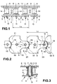
- the plate conveyor chain shown in the figures comprises alternately arranged one on the other Outer chain links 1 and inner chain links 2, each at an articulation point G are connected to each other.
- each joint point G has a bolt 3, which is assigned to the outer chain link 1 and comprises a sleeve 4 which the inner chain link 2 is assigned.
- the bolt 3 has a cylindrical shape 3 with an axis A. and extends through the opening of the cylinder sleeve 4 of the inner chain link 2.
- the outer chain link 1 further comprises an outer plate 5, which by means of a press connection connected to the end regions 6 of the two bolts 3 of an outer chain link 1 is.
- the opposite end regions 7 of the two bolts 3 of an outer chain link 1 are connected to a transport plate 8, the function on this side the second outer tab takes over.
- the end regions 7 are each in a bore 9 the transport plate 8 added.
- the end faces 10 close at the end region 7 substantially flush with the transport surface 11 of the transport plate 8.
- By the lining up of the transport plates 8 of the outer chain links 1 creates a desired one Apron.
- Each transport plate 8 is one by means of the two bolts 3 Outer chain link 1 firmly connected. This is done by a press fit on the End areas 7 in interaction with the bore 9.
- the transport plate 8 is parallel arranged to the outer plate 5 and has essentially the same thickness.
- the inner chain link 2 essentially comprises two arranged parallel to each other Inner tabs 12 and 13 which are connected to one another by means of the sleeve 4.
- the sleeve 4 is pressed into corresponding holes in the tabs 12 and 13, so that the end faces close the sleeve 4 flush with the outside of the tabs 12 and 13.
- the Sleeve 4 and the bolt 3 form an articulation point G, so that the inner chain link 2 opposite the outer chain link 1 is pivotable about the axis A.
- On the outside surface the sleeve 4 is still a roller 14 in the illustrated embodiment rotatably mounted, which should reduce wear at this point.
- Every inner chain link 2 are correspondingly assigned to two sleeves 4.
- the center distance of the sleeve axes 4 essentially corresponds to the center distance of the axes A of the bolts 3 of the outer chain link 1.
- each transport plate 8 has a length L T which is greater than a length L A of an outer plate 5. Furthermore, the transport plate 8 has a semicircular projection 15 on its one end face, which is symmetrical to the central axis M is formed. The projection 15 is narrower than the greatest width B of the transport plate 8. The projection 15 extends over approximately half the total length L T of the transport plate 8 and projects beyond the end face 16 accordingly.
- One of the hinge points G is located in the region of the projection 15, the axis A forming the center for the circular arc of the projection 15.
- the opposite end face 17 has an arcuate recess 18, within which the arcuate section of the projection 15 of the adjacent transport plate 8 is arranged. This leaves a small circular gap 19.
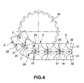
- the circular arc shape of the recess 18 also has the axis A of the adjacent projection 15 as the center. So that the plate chain can also travel around tight curves, there is a transport plate 8 between the end face 16 and the end face 17 of the other Transport plate 8 a gap 20 is arranged, which serves to catch corresponding movements of the transport plates 8. There is the possibility of bridging or covering these gaps 20 in later operation by means of suitable measures. In particular, strips that are assigned to the underside of the transport plates 8 are suitable for a covering.
- the chain could, for example, run in a suitable C profile, the transport plates 8 being located outside the C profile rail and the C webs closing the gap 20 accordingly from below.
- the main difference of this second embodiment of a plate belt chain is the design of the transport plates 8. This is still provided with holes 9, that sit firmly on the end regions of the bolts 3. Looking at the transport plate 8 in side view, like Fig. 5, it can be seen that the transport surface 11 of the transport plate 8 is not continuous, but that above and below the center line M thickness-reducing recesses 21 are formed. The remaining one The rest of the carrier plate, which forms the bottom 22 of the recess 21, has something less than half the thickness of the total thickness of the transport plate 8. The middle area 23 of the transport plate 8, which comprises the two holes 9, has the complete Thickness of the transport plate 8.
- Mirror-symmetrical to a mirror axis S that perpendicularly intersects the central axis M are on the rear 24 of the transport plate 8 also recesses 25 formed above and below the center line M. Based 6 can be seen very well that the recesses 21, which are in FIG. 6 to the right of the axis of symmetry S, are open at the top, whereas the recesses 25, the left of the axis of symmetry S above and below the center line M are arranged, are open to the rear 24 of the transport plate 8.
- this transport plate 8 is made of a rectangular one Basic shape is formed, with each facing the adjacent transport plate 8 Side edges 26 and 27 are each provided with a segment-shaped recess.
- the recesses 21 are towards the raised central region 23 of the transport plate 8 delimited by an essentially S-shaped side edge 28.
- the recess 25 is delimited on the rear side 24 by means of the S-shape curved side edges 29.
- the transport plate 8 instead of that it is made from a single piece, even from two identically shaped ones Plate elements can be manufactured. These two plate elements are then mirror-symmetrical to the axis of symmetry S (this is arranged centrally to the bores 9) placed one on top of the other so that their bores 9 are aligned. Then be the two plate elements are pressed onto the end regions 7 of the bolts 8. advance welding of such plate elements, e.g. by spot welding. If one uses plate elements of the same design, it can be due to the Reduce the thickness of the individual plates to create a secure plate conveyor chain without any noteworthy Increase manufacturing costs.
Landscapes
- Engineering & Computer Science (AREA)
- Mechanical Engineering (AREA)
- Chain Conveyers (AREA)
- Belt Conveyors (AREA)
Claims (9)
- Chaíne à palettes comportant des éléments de chaíne (1, 2) reliés les uns aux autres au niveau de points d'articulation (G), dans laquelle les points d'articulation (G) comprennent au moins une douille (4) et un boulon (3), et comportant des plaques de transport (8) disposées au moins sur un côté des éléments de chaíne (1, 2), qui comprennent une surface de transport (11) plane, qui forment conjointement une palette, qui sont respectivement reliés de façon fixe à un boulon (3) compris dans un point d'articulation (G) et dont la surface de transport (11) ne dépasse pas des zones d'extrémité (7) des boulons (3), chaque plaque de transport (8) étant reliée de façon fixe par deux boulons (3) adjacents de deux points d'articulation (G) adjacents,
caractérisée en ce que la plaque de transport (8) remplace un des maillons externes d'un élément de chaíne (1). - Chaíne à palettes selon la revendication 1,
caractérisée en ce que les éléments de chaíne internes et externes (1,2) sont reliés de façon alternée, en ce que les éléments de chaíne internes (2) comportent deux maillons internes (12, 13) disposés parallèlement l'un à l'autre et deux douilles (4) les reliant l'un à l'autre, et les éléments de chaíne externes (1) comportent deux maillons externes (5, 8) disposés parallèlement l'un à l'autre et deux boulons (3) les reliant l'un à l'autre, une douille (4) de l'élément de chaíne interne (2) et un boulon (3) de l'élément de chaíne externe (1) étant compris respectivement dans un point d'articulation (G), et en ce que la longueur (LT) d'une plaque de transport (8) est supérieure à la longueur (LA) d'un élément de chaíne (LA). - Chaíne à palettes selon l'une des revendications précédentes,
caractérisée en ce que les plaques de transport (8) présentent deux perçages (9) et en ce que dans chacun des deux perçages (9) est enfoncée une zone d'extrémité (7) d'un boulon (3). - Chaíne à palettes selon l'une des revendications précédentes,
caractérisée en ce que les boulons (3) présentent une forme cylindrique d'un diamètre qui reste constant. - Chaíne à palettes selon l'une des revendications précédentes,
caractérisée en ce qu'une face avant (16) de la plaque de transport (8) présente une saillie (15) avec des zones d'arête-en forme de demi-cercle, laquelle est disposée symétriquement par rapport à la ligne médiane (M) de la plaque de transport (8) et présente un rayon qui correspond sensiblement à la moitié de l'écart au centre des boulons (3). - Chaíne à palettes selon l'une des revendications précédentes,
caractérisée en ce que l'autre face (17) de la plaque de transport (11) présente un évidement (18) en forme de demi-cercle disposé symétriquement par rapport à la ligne médiane (M) de la plaque de transport (8), dans lequel est disposée la zone d'arête semi-circulaire de la saillie (15) de la plaque de transport adjacente (8). - Chaíne à palettes selon l'une des revendications précédentes,
caractérisée en ce que les plaques de transport (8) présentent des zones de recouvrement qui sont formées de façon telle qu'elles passent sous une plaque de transport (8) adjacente et que des creux (20) de la surface de transport (11) sont essentiellement recouverts par ces zones depuis le dessous. - Chaíne à palettes selon la revendication 7,
caractérisée en ce que les zones de recouvrement sont formées par des évidements (21) par réduction d'épaisseur au niveau de la surface de transport (11) des plaques de transport (8), et en ce que les segments des plaques de transport (8) qui passent dessous présentent des évidements par réduction d'épaisseur (25) correspondants au niveau de la partie inférieure (24) des plaques de transport (8), dans lesquels les zones de recouvrement sont disposées de façon sensiblement affleurante. - Chaíne à palettes selon la revendication 7 ou 8,
caractérisée en ce que les plaques de transport (8) sont réalisées par deux éléments de plaque (8) disposés l'un au dessus de l'autre et façonnés de façon sensiblement similaire, lesquels sont disposés de façon à former les zones de recouvrement, en étant symétriques des segments s'insérant dessous, par rapport à un axe de symétrie (S) s'étendant perpendiculairement à l'axe de la chaíne.
Applications Claiming Priority (2)
| Application Number | Priority Date | Filing Date | Title |
|---|---|---|---|
| DE29807758U DE29807758U1 (de) | 1998-04-29 | 1998-04-29 | Plattenbandkette |
| DE29807758U | 1998-04-29 |
Publications (3)
| Publication Number | Publication Date |
|---|---|
| EP0953521A2 EP0953521A2 (fr) | 1999-11-03 |
| EP0953521A3 EP0953521A3 (fr) | 2001-01-10 |
| EP0953521B1 true EP0953521B1 (fr) | 2003-04-09 |
Family
ID=8056481
Family Applications (1)
| Application Number | Title | Priority Date | Filing Date |
|---|---|---|---|
| EP99107682A Expired - Lifetime EP0953521B1 (fr) | 1998-04-29 | 1999-04-16 | Chaíne à palettes |
Country Status (3)
| Country | Link |
|---|---|
| US (1) | US6196380B1 (fr) |
| EP (1) | EP0953521B1 (fr) |
| DE (2) | DE29807758U1 (fr) |
Families Citing this family (11)
| Publication number | Priority date | Publication date | Assignee | Title |
|---|---|---|---|---|
| ES2246211T3 (es) * | 2000-04-18 | 2006-02-16 | Machinefabriek Bollegraaf Appingedam B.V. | Transportador para el transporte de materiales a granel. |
| DE20114661U1 (de) * | 2001-09-05 | 2002-11-07 | Joh. Winklhofer & Söhne GmbH und Co. KG, 81369 München | Plattenbandkette |
| TWI280186B (en) * | 2004-03-03 | 2007-05-01 | Chum Power Machinery Corp | Method for easily adjusting distance between pre-forms and structure thereof |
| US20110139073A1 (en) * | 2009-12-15 | 2011-06-16 | Primestar Solar, Inc. | Conveyor assembly for a vapor deposition apparatus |
| US8322522B2 (en) | 2010-03-22 | 2012-12-04 | Ramsey Products Corporation | Nested end link and multi-link conveyor chain |
| US8474607B2 (en) | 2010-11-19 | 2013-07-02 | Ramsey Products Corporation | Integrated multi-functional links for chain link conveyor and method |
| MX393875B (es) * | 2015-02-23 | 2025-03-24 | Span Tech Llc | Transportador de eslabones modulares con caracteristicas para mejorar la transportacion eficaz de articulos. |
| EP3348497B1 (fr) | 2017-01-11 | 2020-06-24 | Pennine Industrial Equipment Limited | Chaîne de convoyeur |
| JP6655636B2 (ja) * | 2018-02-09 | 2020-02-26 | 本田技研工業株式会社 | 台車利用の搬送設備 |
| CN108438740A (zh) * | 2018-04-20 | 2018-08-24 | 上海利来链条有限公司 | 一种链板模块 |
| IT202100031997A1 (it) * | 2021-12-21 | 2023-06-21 | Regina Catene Calibrate Spa | Catena di trasporto curvilinea atta a scorrere lungo una guida comprendente almeno un tratto curvo. |
Family Cites Families (12)
| Publication number | Priority date | Publication date | Assignee | Title |
|---|---|---|---|---|
| BE464745A (fr) * | ||||
| DE1049302B (fr) * | 1959-01-22 | |||
| US2685361A (en) * | 1948-02-10 | 1954-08-03 | Mechanical Handling Sys Inc | Floor type conveyer chain |
| DE1056523B (de) * | 1954-03-18 | 1959-04-30 | Julius Lippert | Vorrichtung zum Herstellen und Trocknen keramischer Gegenstaende, insbesondere Tassen |
| US3738478A (en) * | 1971-03-26 | 1973-06-12 | Cross Co | Conveyor chain |
| DE7713782U1 (de) * | 1977-05-02 | 1977-09-29 | Kabel- Und Lackdrahtfabriken Gmbh, 6800 Mannheim | Transportkette |
| DE2822196A1 (de) * | 1978-05-20 | 1979-11-22 | Band Egon | Kardanisch gelenkige kurvengaengige zug- bzw. tragfoerderkette |
| DE3321018A1 (de) * | 1983-06-10 | 1984-12-13 | Otmar Fahrion | Ketten-foerdereinheit |
| DE8519209U1 (de) * | 1985-07-02 | 1985-11-28 | Joh. Winklhofer & Söhne, 8000 München | Förderkette |
| DE3723591A1 (de) * | 1987-07-16 | 1989-01-26 | Gebr Hennig Gmbh | Spaenefoerderer |
| US4893709A (en) * | 1988-08-18 | 1990-01-16 | Rexnord Corporation | Back-flexing article carrying chain |
| DE4140206A1 (de) * | 1991-12-05 | 1993-06-09 | Johann A. Krause Maschinenfabrik Gmbh, 2820 Bremen, De | Vorrichtung zum transport von gegenstaenden |
-
1998
- 1998-04-29 DE DE29807758U patent/DE29807758U1/de not_active Expired - Lifetime
-
1999
- 1999-04-16 EP EP99107682A patent/EP0953521B1/fr not_active Expired - Lifetime
- 1999-04-16 DE DE59904914T patent/DE59904914D1/de not_active Expired - Fee Related
- 1999-04-26 US US09/299,845 patent/US6196380B1/en not_active Expired - Fee Related
Also Published As
| Publication number | Publication date |
|---|---|
| US6196380B1 (en) | 2001-03-06 |
| DE29807758U1 (de) | 1999-09-09 |
| DE59904914D1 (de) | 2003-05-15 |
| EP0953521A2 (fr) | 1999-11-03 |
| EP0953521A3 (fr) | 2001-01-10 |
Similar Documents
| Publication | Publication Date | Title |
|---|---|---|
| DE69202287T2 (de) | Modulare Förderkette mit offener Gelenkbolzenkonstruktion. | |
| DE68915399T2 (de) | Horizontal biegsames Förderband. | |
| DE2914067A1 (de) | Rollenkette | |
| DE2806209A1 (de) | Foerderer und insbesondere gliederfoerderer | |
| EP0953521B1 (fr) | Chaíne à palettes | |
| DE69606849T2 (de) | Förderkette mit Dichtungs-und Rückhaltestopfen für Scharnierstift | |
| DE2356289B1 (de) | Laschenkette für Kegelscheibengetriebe | |
| DD256902A5 (de) | Energiefuehrungskette | |
| DE19547846B4 (de) | Rollenkettenbolzen mit minimalem Überstand | |
| EP1318955B1 (fr) | Chaine de transporteur a tabliers | |
| EP1093996B1 (fr) | Chenille pour véhicules à chenilles | |
| WO2006002722A1 (fr) | Chaine dentee | |
| DE102016111542B4 (de) | Schubkette mit standardisiertem Endstück | |
| EP2960545B1 (fr) | Chaîne de poussée autoportante | |
| EP2029299A1 (fr) | Chaîne articulée plate facile à monter | |
| DE19515184A1 (de) | Hochleistungs-Antriebskette für stufenlose Getriebe mit Kegelscheiben | |
| DE69413168T2 (de) | Zweiflügelige falttür | |
| EP1977136A2 (fr) | Chaine | |
| DE29709113U1 (de) | Gelenkkette | |
| EP1495996B1 (fr) | Convoyeur à charnieres avec dispositif de guidage | |
| EP0767114A1 (fr) | Chaîne de galle | |
| EP1059467A1 (fr) | Chaíne rigide dans une direction | |
| DE19746580A1 (de) | Baukastensystem zur Zusammenstellung von Schließzylindern | |
| EP1070012B1 (fr) | Element de chaine pour une chaine de convoyeur, en particulier pour une chaine de tapis de transport | |
| EP4015869A1 (fr) | Chaîne de poussée rigide au glissement actionnable par un entraînement à chaîne |
Legal Events
| Date | Code | Title | Description |
|---|---|---|---|
| PUAI | Public reference made under article 153(3) epc to a published international application that has entered the european phase |
Free format text: ORIGINAL CODE: 0009012 |
|
| AK | Designated contracting states |
Kind code of ref document: A2 Designated state(s): BE DE FR GB IT NL |
|
| AX | Request for extension of the european patent |
Free format text: AL;LT;LV;MK;RO;SI |
|
| RTI1 | Title (correction) |
Free format text: PLATE CHAIN |
|
| K1C1 | Correction of patent application (title page) published |
Effective date: 19991103 |
|
| PUAL | Search report despatched |
Free format text: ORIGINAL CODE: 0009013 |
|
| AK | Designated contracting states |
Kind code of ref document: A3 Designated state(s): AT BE CH CY DE DK ES FI FR GB GR IE IT LI LU MC NL PT SE |
|
| AX | Request for extension of the european patent |
Free format text: AL;LT;LV;MK;RO;SI |
|
| 17P | Request for examination filed |
Effective date: 20010313 |
|
| 17Q | First examination report despatched |
Effective date: 20010508 |
|
| AKX | Designation fees paid |
Free format text: BE DE FR GB IT NL |
|
| RTI1 | Title (correction) |
Free format text: PLATFORM CHAIN |
|
| RTI1 | Title (correction) |
Free format text: PLATFORM CHAIN |
|
| GRAG | Despatch of communication of intention to grant |
Free format text: ORIGINAL CODE: EPIDOS AGRA |
|
| GRAG | Despatch of communication of intention to grant |
Free format text: ORIGINAL CODE: EPIDOS AGRA |
|
| GRAG | Despatch of communication of intention to grant |
Free format text: ORIGINAL CODE: EPIDOS AGRA |
|
| GRAH | Despatch of communication of intention to grant a patent |
Free format text: ORIGINAL CODE: EPIDOS IGRA |
|
| GRAH | Despatch of communication of intention to grant a patent |
Free format text: ORIGINAL CODE: EPIDOS IGRA |
|
| GRAA | (expected) grant |
Free format text: ORIGINAL CODE: 0009210 |
|
| AK | Designated contracting states |
Designated state(s): BE DE FR GB IT NL |
|
| REG | Reference to a national code |
Ref country code: GB Ref legal event code: FG4D |
|
| PGFP | Annual fee paid to national office [announced via postgrant information from national office to epo] |
Ref country code: GB Payment date: 20030410 Year of fee payment: 5 |
|
| PGFP | Annual fee paid to national office [announced via postgrant information from national office to epo] |
Ref country code: NL Payment date: 20030417 Year of fee payment: 5 Ref country code: FR Payment date: 20030417 Year of fee payment: 5 |
|
| PGFP | Annual fee paid to national office [announced via postgrant information from national office to epo] |
Ref country code: BE Payment date: 20030418 Year of fee payment: 5 |
|
| REG | Reference to a national code |
Ref country code: GB Ref legal event code: FG4C Free format text: NOTIFICATION RECEIVED FROM THE EUROPEAN PATENT OFFICE THAT THE PUBLICATION LANGUAGE IS ACTUALLY GERMAN. |
|
| PGFP | Annual fee paid to national office [announced via postgrant information from national office to epo] |
Ref country code: DE Payment date: 20030528 Year of fee payment: 5 |
|
| GBT | Gb: translation of ep patent filed (gb section 77(6)(a)/1977) | ||
| ET | Fr: translation filed | ||
| PLBE | No opposition filed within time limit |
Free format text: ORIGINAL CODE: 0009261 |
|
| STAA | Information on the status of an ep patent application or granted ep patent |
Free format text: STATUS: NO OPPOSITION FILED WITHIN TIME LIMIT |
|
| 26N | No opposition filed |
Effective date: 20040112 |
|
| PG25 | Lapsed in a contracting state [announced via postgrant information from national office to epo] |
Ref country code: GB Free format text: LAPSE BECAUSE OF NON-PAYMENT OF DUE FEES Effective date: 20040416 |
|
| PG25 | Lapsed in a contracting state [announced via postgrant information from national office to epo] |
Ref country code: BE Free format text: LAPSE BECAUSE OF NON-PAYMENT OF DUE FEES Effective date: 20040430 |
|
| BERE | Be: lapsed |
Owner name: JOH. *WINKLHOFER & SOHNE G.M.B.H. & CO. K.G. Effective date: 20040430 |
|
| PG25 | Lapsed in a contracting state [announced via postgrant information from national office to epo] |
Ref country code: NL Free format text: LAPSE BECAUSE OF NON-PAYMENT OF DUE FEES Effective date: 20041101 |
|
| PG25 | Lapsed in a contracting state [announced via postgrant information from national office to epo] |
Ref country code: DE Free format text: LAPSE BECAUSE OF NON-PAYMENT OF DUE FEES Effective date: 20041103 |
|
| GBPC | Gb: european patent ceased through non-payment of renewal fee |
Effective date: 20040416 |
|
| PG25 | Lapsed in a contracting state [announced via postgrant information from national office to epo] |
Ref country code: FR Free format text: LAPSE BECAUSE OF NON-PAYMENT OF DUE FEES Effective date: 20041231 |
|
| NLV4 | Nl: lapsed or anulled due to non-payment of the annual fee |
Effective date: 20041101 |
|
| REG | Reference to a national code |
Ref country code: FR Ref legal event code: ST |
|
| PG25 | Lapsed in a contracting state [announced via postgrant information from national office to epo] |
Ref country code: IT Free format text: LAPSE BECAUSE OF NON-PAYMENT OF DUE FEES;WARNING: LAPSES OF ITALIAN PATENTS WITH EFFECTIVE DATE BEFORE 2007 MAY HAVE OCCURRED AT ANY TIME BEFORE 2007. THE CORRECT EFFECTIVE DATE MAY BE DIFFERENT FROM THE ONE RECORDED. Effective date: 20050416 |