EP0953527B1 - Unit for forming stacks of articles - Google Patents
Unit for forming stacks of articles Download PDFInfo
- Publication number
- EP0953527B1 EP0953527B1 EP99103580A EP99103580A EP0953527B1 EP 0953527 B1 EP0953527 B1 EP 0953527B1 EP 99103580 A EP99103580 A EP 99103580A EP 99103580 A EP99103580 A EP 99103580A EP 0953527 B1 EP0953527 B1 EP 0953527B1
- Authority
- EP
- European Patent Office
- Prior art keywords
- unit
- unloading
- stacks
- supply
- level
- Prior art date
- Legal status (The legal status is an assumption and is not a legal conclusion. Google has not performed a legal analysis and makes no representation as to the accuracy of the status listed.)
- Expired - Lifetime
Links
- 238000004804 winding Methods 0.000 claims description 2
- 125000004122 cyclic group Chemical group 0.000 description 2
- 230000000284 resting effect Effects 0.000 description 1
Images

Classifications
-
- B—PERFORMING OPERATIONS; TRANSPORTING
- B65—CONVEYING; PACKING; STORING; HANDLING THIN OR FILAMENTARY MATERIAL
- B65G—TRANSPORT OR STORAGE DEVICES, e.g. CONVEYORS FOR LOADING OR TIPPING, SHOP CONVEYOR SYSTEMS OR PNEUMATIC TUBE CONVEYORS
- B65G57/00—Stacking of articles
- B65G57/30—Stacking of articles by adding to the bottom of the stack
- B65G57/305—Stacking of articles by adding to the bottom of the stack by means of rotary devices or endless elements
- B65G57/307—Stacking of articles by adding to the bottom of the stack by means of rotary devices or endless elements the rotary devices being screws
Definitions
- the present invention relates to a unit for forming stacks of articles.
- Known units for forming stacks of articles normally comprise a stacking device for forming the articles into stacks; a supply device for feeding the articles to the stacking device in a given supply direction; and a further supply device for feeding the stacks of articles from the stacking device along an unloading path extending parallel to the supply direction.
- both DE-A-1127810 and US-A-4314785 disclose a unit for forming stacks of articles, the unit comprising stacking means for forming the stacks, supply means for feeding the articles to an input of the stacking means in a first supply direction, and unloading means in series with the stacking means to unload the stacks from an output of the stacking means and feed the stacks in a second supply direction perpendicular to the first supply direction.
- the unloading means comprise a plate for accumulating the stacks and located at an unloading level higher than a supply level defined by the input of the stacking means.
- the preamble of claim 1 is based on document US-A-4 314 785.
- Number 1 in Figures 1 and 2 indicates as a whole a unit for forming stacks 2 of articles 3, and which comprises a double-screw stacking device 4 for forming stacks 2; a supply device 5 for successively feeding articles 3 in a supply direction D1 to an input 6 of stacking device 4; and an unloading assembly 7 located in series with stacking device 4 to unload stacks 2 from an output 8 of stacking device 4 and feed stacks 2 in a further supply direction D2 perpendicular to direction D1.
- Device 5 comprises an endless conveyor belt 9, which defines an input path P1 of unit 1 extending up to input 6 of stacking device 4, has a number of conveying pockets 10, equally spaced with a spacing K, for conveying respective articles, and provides for continuously feeding articles 3 crosswise to the respective long longitudinal axes 3a of articles 3.
- Belt 9 has a horizontal conveying branch 11, which is located at a supply level L1 lower than the unloading level L2 of stacks 2 off stacking device 4, and extends through input 6 of stacking device 4.
- Stacking device 4 comprises two counter-rotating screws 12, which are fitted, on opposite sides of conveying branch 11 of device 5, to a base 13, rotate about respective vertical axes 12a of rotation, and comprise respective oppositely-inclined threads 14 winding about respective axes 12a. More specifically, threads 14 are tangent to both input 6 and the sides of branch 11, and, being cut at the top by a surface crosswise to axes 12a, define a surface 15 for forming stacks 2 and which is located at an intermediate level L3 between levels L1 and L2.
- Stacking device 4 also comprises a lift device 16 for lifting stacks 2 from level L3 to level L2, and which in turn comprises a linear actuator 17 fitted to base 13 alongside one of screws 12 and having an output arm 18 movable up and down in a lift direction D4 parallel to axes 12a, and a curved plate element 19 fitted to the top end of arm 18.
- Lift device 16 also comprises a known angular actuator (not shown) associated with actuator 17 to move arm 18, about an axis 18a defined by arm 18 itself and in direction D4, between a lowered engaging position in which a square end portion 20 of curved element 19 is located at the same level L3 as surface 15 between threads 14, a raised unloading position in which portion 20 is located at level L2 at output 8, and a raised and/or lowered release position.
- a known angular actuator (not shown) associated with actuator 17 to move arm 18, about an axis 18a defined by arm 18 itself and in direction D4, between a lowered engaging position in which a square end portion 20 of curved element 19 is located at the same level L3 as surface 15 between threads 14, a raised unloading position in which portion 20 is located at level L2 at output 8, and a raised and/or lowered release position.
- Unloading assembly 7 comprises a plate 21 at level L2 for accumulating stacks 2; and a pocket conveying device 22 movable in a supply direction D3 parallel to direction D1 and along an unloading path P2 extending through output 8 and through a switch station 23 defined by plate 21 and located downstream from output 8.
- Unloading assembly 7 also comprises a belt conveyor 24 having a conveying branch 25 coplanar with plate 21 and extending in direction D2 from station 23; and a blade device 26 for releasing stacks 2 from conveying device 22 and unloading stacks 2 off plate 21 onto conveyor 24.
- Conveying device 22 comprises five pockets 27, each for receiving a respective stack 2 at output 8, and which are located in series and side by side with one another in direction D3, and are defined by six vertical walls 28 crosswise to direction D3.
- Conveying device 22 also comprises a linear actuator 29, the output arm 30 of which supports walls 28 and moves back and forth in direction D3 to arrest pockets 27 one after the other at output 8 and so feed pockets 27 in steps onto plate 21, and to withdraw pockets 27 all together off plate 21.
- Blade device 26 comprises a blade 31, which is movable cyclically through switch station 23 in direction D2, and has four through openings 32 for the passage of walls 28 when unloading conveying device 22.
- Device 26 also comprises a cyclic actuator 33 located alongside conveyor 24 and at the end of plate 21, and which provides for moving blade 31 along a cyclic path while keeping blade 31 parallel to itself and perpendicular to direction D2.
- actuator 33 provides for moving blade 31 from an initial lowered position - in which blade 31 is adjacent to all of pockets 27 arrested in switch station 23 and containing respective stacks 2 - to a final lowered position - in which blade 31 is located on conveying branch 25 of conveyor 24 - and through two raised positions in which blade 31 is located at such a height over branch 25 and plate 21 as to fully clear stacks 2.
- Unit 1 is mainly used for stacking so-called "pillow-pack” articles 3 comprising a central body 34, and two lateral tabs 35 at opposite ends of body 34 and crosswise to longitudinal axis 3a.
- Articles 3 are housed inside conveying pockets 10 of device 5 with respective tabs 35 projecting laterally outwards of conveying branch 11 of belt 9, and are fed continuously by pockets 10 to input 6, where the two threads 14, rotating in opposite directions and at substantially constant angular speed about respective axes 12a, simultaneously engage both tabs 35 and lift each article 3 in direction D4.
- Articles 3 are raised by threads 14 from level L1 to level L3 defined by forming surface 15, and remain with respective tabs 35 resting on screws 12 until a stack 2 is formed by stacking articles 3 underneath one another. Once a stack 2 is formed on surface 15, plate element 19 - initially set to the lowered release position - is rotated about axis 18a, and square end portion 20 - which, in horizontal section, is substantially the same size as body 34 of article 3 - is inserted beneath the newly formed stack 2.
- Actuator 17 is then operated to move element 19 in direction D4 and lift the newly formed stack 2 from level L3 to level L2; and portion 20 is positioned flush with plate 21 and just beneath walls 28, so that stack 2 is inserted inside a pocket 27 arrested at output 8. Once stack 2 is fully inserted inside respective pocket 27, pocket 27 is moved one step, equal to the width of pocket 27 itself, in direction D3 so that stack 2 slides off portion 20 onto plate 21.
- blade device 26 When pockets 27 and respective stacks 2 have all been fed into switch station 23, blade device 26 unloads pockets 27 and feeds the stacks onto conveying branch 25 of conveyor 24.
- Pockets 27 are unloaded by moving blade 31 into the initial lowered position and feeding blade 31 in direction D2 to engage the articles 3 stacked inside pockets 27 and slide stacks 2 off plate 21 onto conveyor 24, which is operated in steps to feed stacks 2 in direction D3.
- actuator 29 resets one pocket 27 at output 8. The time taken by blade 31 to unload pockets 27, and by actuator 29 to reset a pocket 27 at output 8, is substantially equal to the time taken by stacking device to form a stack 2.
- Articles 3 are therefore fed to input 6 singly and crosswise to respective axes 3a, and are subsequently fed parallel to axes 3a in direction D2 by conveyor 24 and device 26. Feeding stacks 2 of articles 3 out in a direction D2 perpendicular to the infeed direction D1 of articles 3 provides for reducing the length of unit 1, and so enabling unit 1, unlike units of considerable length for forming stacks 2 of articles 3, to be installed in confined workplaces.
Landscapes
- Engineering & Computer Science (AREA)
- Mechanical Engineering (AREA)
- Branching, Merging, And Special Transfer Between Conveyors (AREA)
- Chemical Vapour Deposition (AREA)
- Pile Receivers (AREA)
Description
- The present invention relates to a unit for forming stacks of articles.
- Known units for forming stacks of articles normally comprise a stacking device for forming the articles into stacks; a supply device for feeding the articles to the stacking device in a given supply direction; and a further supply device for feeding the stacks of articles from the stacking device along an unloading path extending parallel to the supply direction.
- For example, both DE-A-1127810 and US-A-4314785 disclose a unit for forming stacks of articles, the unit comprising stacking means for forming the stacks, supply means for feeding the articles to an input of the stacking means in a first supply direction, and unloading means in series with the stacking means to unload the stacks from an output of the stacking means and feed the stacks in a second supply direction perpendicular to the first supply direction. The unloading means comprise a plate for accumulating the stacks and located at an unloading level higher than a supply level defined by the input of the stacking means.
- The preamble of
claim 1 is based on document US-A-4 314 785. - Though highly reliable and easy to produce and operate, units for forming stacks of articles of the above type have several drawbacks, mainly on account of their structure, which prevents their being used in confined work areas.
- It is an object of the present invention to provide a straightforward, low-cost unit for forming stacks of articles, designed to eliminate the aforementioned drawbacks.
- According to the present invention, there is provided a unit for forming stacks of articles as recited by
claim 1. - The invention will now be described by way of example with reference to the accompanying drawings, in which:
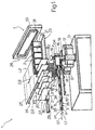
- Figure 1 shows a view in perspective, with parts removed for clarity, of a preferred embodiment of the unit for forming stacks of articles according to the present invention;
- Figure 2 shows a larger-scale plan view of the Figure 1 unit.
-
-
Number 1 in Figures 1 and 2 indicates as a whole a unit for formingstacks 2 ofarticles 3, and which comprises a double-screw stacking device 4 for formingstacks 2; a supply device 5 for successively feedingarticles 3 in a supply direction D1 to aninput 6 of stacking device 4; and anunloading assembly 7 located in series with stacking device 4 to unloadstacks 2 from an output 8 of stacking device 4 andfeed stacks 2 in a further supply direction D2 perpendicular to direction D1. - Device 5 comprises an endless conveyor belt 9, which defines an input path P1 of
unit 1 extending up toinput 6 of stacking device 4, has a number ofconveying pockets 10, equally spaced with a spacing K, for conveying respective articles, and provides for continuously feedingarticles 3 crosswise to the respective long longitudinal axes 3a ofarticles 3. Belt 9 has ahorizontal conveying branch 11, which is located at a supply level L1 lower than the unloading level L2 ofstacks 2 off stacking device 4, and extends throughinput 6 of stacking device 4. - Stacking device 4 comprises two
counter-rotating screws 12, which are fitted, on opposite sides of conveyingbranch 11 of device 5, to abase 13, rotate about respectivevertical axes 12a of rotation, and comprise respective oppositely-inclined threads 14 winding aboutrespective axes 12a. More specifically,threads 14 are tangent to bothinput 6 and the sides ofbranch 11, and, being cut at the top by a surface crosswise toaxes 12a, define asurface 15 for formingstacks 2 and which is located at an intermediate level L3 between levels L1 and L2. - Stacking device 4 also comprises a
lift device 16 forlifting stacks 2 from level L3 to level L2, and which in turn comprises alinear actuator 17 fitted tobase 13 alongside one ofscrews 12 and having anoutput arm 18 movable up and down in a lift direction D4 parallel toaxes 12a, and acurved plate element 19 fitted to the top end ofarm 18. -
Lift device 16 also comprises a known angular actuator (not shown) associated withactuator 17 to movearm 18, about anaxis 18a defined byarm 18 itself and in direction D4, between a lowered engaging position in which asquare end portion 20 ofcurved element 19 is located at the same level L3 assurface 15 betweenthreads 14, a raised unloading position in whichportion 20 is located at level L2 at output 8, and a raised and/or lowered release position. -
Unloading assembly 7 comprises aplate 21 at level L2 for accumulatingstacks 2; and apocket conveying device 22 movable in a supply direction D3 parallel to direction D1 and along an unloading path P2 extending through output 8 and through aswitch station 23 defined byplate 21 and located downstream from output 8.Unloading assembly 7 also comprises abelt conveyor 24 having aconveying branch 25 coplanar withplate 21 and extending in direction D2 fromstation 23; and ablade device 26 for releasingstacks 2 fromconveying device 22 and unloadingstacks 2 offplate 21 ontoconveyor 24. - Conveying
device 22 comprises fivepockets 27, each for receiving arespective stack 2 at output 8, and which are located in series and side by side with one another in direction D3, and are defined by sixvertical walls 28 crosswise to direction D3. Conveyingdevice 22 also comprises alinear actuator 29, theoutput arm 30 of which supportswalls 28 and moves back and forth in direction D3 to arrestpockets 27 one after the other at output 8 and so feedpockets 27 in steps ontoplate 21, and to withdrawpockets 27 all together offplate 21. -
Blade device 26 comprises ablade 31, which is movable cyclically throughswitch station 23 in direction D2, and has four throughopenings 32 for the passage ofwalls 28 when unloadingconveying device 22.Device 26 also comprises acyclic actuator 33 located alongsideconveyor 24 and at the end ofplate 21, and which provides for movingblade 31 along a cyclic path while keepingblade 31 parallel to itself and perpendicular to direction D2. - More specifically,
actuator 33 provides for movingblade 31 from an initial lowered position - in whichblade 31 is adjacent to all ofpockets 27 arrested inswitch station 23 and containing respective stacks 2 - to a final lowered position - in whichblade 31 is located on conveyingbranch 25 of conveyor 24 - and through two raised positions in whichblade 31 is located at such a height overbranch 25 andplate 21 as to fullyclear stacks 2. -
Unit 1 is mainly used for stacking so-called "pillow-pack"articles 3 comprising a central body 34, and twolateral tabs 35 at opposite ends of body 34 and crosswise to longitudinal axis 3a. -
Articles 3 are housed inside conveyingpockets 10 of device 5 withrespective tabs 35 projecting laterally outwards of conveyingbranch 11 of belt 9, and are fed continuously bypockets 10 to input 6, where the twothreads 14, rotating in opposite directions and at substantially constant angular speed aboutrespective axes 12a, simultaneously engage bothtabs 35 and lift eacharticle 3 in direction D4. -
Articles 3 are raised bythreads 14 from level L1 to level L3 defined by formingsurface 15, and remain withrespective tabs 35 resting onscrews 12 until astack 2 is formed by stackingarticles 3 underneath one another. Once astack 2 is formed onsurface 15, plate element 19 - initially set to the lowered release position - is rotated aboutaxis 18a, and square end portion 20 - which, in horizontal section, is substantially the same size as body 34 of article 3 - is inserted beneath the newly formedstack 2. -
Actuator 17 is then operated to moveelement 19 in direction D4 and lift the newly formedstack 2 from level L3 to level L2; andportion 20 is positioned flush withplate 21 and just beneathwalls 28, so thatstack 2 is inserted inside apocket 27 arrested at output 8. Oncestack 2 is fully inserted insiderespective pocket 27,pocket 27 is moved one step, equal to the width ofpocket 27 itself, in direction D3 so that stack 2 slides offportion 20 ontoplate 21. - When
pockets 27 andrespective stacks 2 have all been fed intoswitch station 23,blade device 26unloads pockets 27 and feeds the stacks onto conveyingbranch 25 ofconveyor 24. -
Pockets 27 are unloaded by movingblade 31 into the initial lowered position and feedingblade 31 in direction D2 to engage thearticles 3 stacked insidepockets 27 andslide stacks 2 offplate 21 ontoconveyor 24, which is operated in steps to feedstacks 2 in direction D3. Oncepockets 27 have been unloaded,actuator 29 resets onepocket 27 at output 8. The time taken byblade 31 to unloadpockets 27, and byactuator 29 to reset apocket 27 at output 8, is substantially equal to the time taken by stacking device to form astack 2. -
Articles 3 are therefore fed to input 6 singly and crosswise to respective axes 3a, and are subsequently fed parallel to axes 3a in direction D2 byconveyor 24 anddevice 26. Feeding stacks 2 ofarticles 3 out in a direction D2 perpendicular to the infeed direction D1 ofarticles 3 provides for reducing the length ofunit 1, and so enablingunit 1, unlike units of considerable length for formingstacks 2 ofarticles 3, to be installed in confined workplaces.
Claims (7)
- A unit for forming stacks (2) of articles; the unit (1) comprising stacking means (4) for forming the stacks (2) and having an input (6) defining a supply level (L1) and an output (8), supply means (5) for feeding the articles (3) to the input (6) in a first supply direction (D1), and unloading means (7) in series with the stacking means (4) to unload the stacks (2) from the output (8) and feed the stacks (2) in a second supply direction (D2) perpendicular to the first supply direction (D1); the unloading means (7) comprising a plate (21) for accumulating the stacks (2) and located at an unloading level (L2) higher than the supply level (L1); the stacking means (4) comprising two screws (12), which rotate in opposite directions about respective first axes (12a) of rotation crosswise to the first supply direction (D1) and comprise respective oppositely-inclined threads (14) winding about the respective first axes (12a) and cut at the top by a surface crosswise to the first axes (12a) for defining a stacking surface (15) for forming stacks (2); the unit (1) being characterized in that the stacking surface (15) is located at an intermediate level (L3) between the supply level (L1) and the unloading level (L2); the stacking means (4) comprising a lifting device (16) movable selectively through the output (8) to lift each stack (2) from the stacking surface (15) at the intermediate level (L3) to the plate (21) at the unloading level (L2); the lifting device (16) comprising an output arm, a plate element (19) fitted to the top end of the output arm (18), and actuating means (17) for moving up and down the output arm (18) in a lift direction (D4) parallel to the first axes (12a) and also for rotating the output arm (18) about a second axis (18a); the plate element (19) being movable between a lowered engaging position, in which a portion (20) of the plate element (19) is located at the intermediate level (L3) and is insertable beneath a newly formed stack (2), and a raised unloading position, in which the portion (20) of the plate element (19) is located at the unloading level (L2).
- A unit as claimed in Claim 1, wherein the plate element (19) is a curved plate element (19).
- A unit as claimed in Claim 1 or 2, wherein the actuating means (17) comprises a linear actuator (17) fitted to a base (13) alongside one of screws (12) and an angular actuator.
- A unit as claimed in Claim 1, 2 or 3, wherein the unloading means (7) comprise further supply means (24, 26) movable parallel to the second supply direction (D2) and through a switch station (23) located along an unloading path (P2) downstream from the output (8), and pocket means (22) movable through the output (8) and the switch station (23) along the unloading path (P2) and in a third supply direction (D3); the pocket means (22) comprising a number of pockets (27) arranged side by side in the third supply direction (D3), and each pocket (27) receiving a respective stack (2) at the output (8) of the stacking means (4).
- A unit as claimed in any one of the foregoing Claims from 1 to 4, wherein the third supply direction (D3) is parallel to the first supply direction (D1).
- A unit as claimed in any one of the foregoing Claims from 1 to 5, wherein the further supply means (24, 26) comprise blade means (26) movable selectively through the pockets (27) at the switch station (23).
- A unit as claimed in Claim 6, wherein the blade means (26) move back and forth in the second supply direction (D2) and crosswise to the pocket means (22).
Applications Claiming Priority (2)
| Application Number | Priority Date | Filing Date | Title |
|---|---|---|---|
| ITBO980110 | 1998-02-25 | ||
| IT98BO000110A IT1299865B1 (en) | 1998-02-25 | 1998-02-25 | UNIT FOR THE FORMATION OF STACKS OF ITEMS. |
Publications (2)
| Publication Number | Publication Date |
|---|---|
| EP0953527A1 EP0953527A1 (en) | 1999-11-03 |
| EP0953527B1 true EP0953527B1 (en) | 2005-04-27 |
Family
ID=11342942
Family Applications (1)
| Application Number | Title | Priority Date | Filing Date |
|---|---|---|---|
| EP99103580A Expired - Lifetime EP0953527B1 (en) | 1998-02-25 | 1999-02-24 | Unit for forming stacks of articles |
Country Status (4)
| Country | Link |
|---|---|
| US (1) | US6155774A (en) |
| EP (1) | EP0953527B1 (en) |
| DE (1) | DE69924913T2 (en) |
| IT (2) | IT1299865B1 (en) |
Families Citing this family (2)
| Publication number | Priority date | Publication date | Assignee | Title |
|---|---|---|---|---|
| US7153089B2 (en) * | 2003-09-12 | 2006-12-26 | Lockheed Martin Corporation | Storage device |
| CN119551450B (en) * | 2024-11-29 | 2025-08-22 | 江苏理工学院 | A logistics cargo palletizing device based on the Internet of Things |
Family Cites Families (13)
| Publication number | Priority date | Publication date | Assignee | Title |
|---|---|---|---|---|
| US1208802A (en) * | 1914-04-16 | 1916-12-19 | Nat Sugar Refining Co | Sugar tablet or cube boxing machine. |
| US2819807A (en) * | 1955-08-08 | 1958-01-14 | Sperry Rand Corp | Counting and stacking device |
| DE1127810B (en) * | 1960-12-21 | 1962-04-12 | Hesser Ag Maschf | Device for stacking prismatic objects, in particular in connection with a device for multipacking the stacked objects |
| GB1260123A (en) * | 1968-11-06 | 1972-01-12 | Wentcroft Engs Ltd | Improvements in or relating to the collation and packing of articles |
| US3712487A (en) * | 1971-02-19 | 1973-01-23 | Ferag Ag | Apparatus for stacking flat surface-like objects |
| US4378938A (en) * | 1979-10-09 | 1983-04-05 | Sweda International, Inc. | Document stacking device |
| US4314785A (en) | 1979-12-26 | 1982-02-09 | Package Machinery Company | Stacking and packaging apparatus |
| IT1218518B (en) * | 1987-10-02 | 1990-04-19 | Gd Spa | FEEDING EQUIPMENT OF GROUPS OF PRODUCTS SUBSTANTIALLY PARALLELEPIPEDI TO AN OPERATING MACHINE |
| US5236300A (en) * | 1989-06-17 | 1993-08-17 | Sanjo Machine Works, Ltd. | Stacking and forwarding apparatus |
| US4957409A (en) * | 1989-08-30 | 1990-09-18 | Kabushiki Kaisha Ishikawa Seisakusho, Ltd. | Corrugated cardboard box stacking device in a corrugated cardboard box making machine |
| US5439344A (en) * | 1994-11-04 | 1995-08-08 | Kabushiki Kaisha Ishikawa Seisakusho, Ltd. | Corrugated cardboard box counting and discharging device |
| IT1285438B1 (en) * | 1996-01-09 | 1998-06-08 | Azionaria Costruzioni Acma Spa | METHOD AND UNIT FOR FORMING STACKS OF ITEMS |
| IT1285694B1 (en) * | 1996-05-08 | 1998-06-18 | Azionaria Costruzioni Acma Spa | METHOD AND UNIT FOR THE TRAINING AND CONVEYANCE OF GROUPS OF PRODUCTS |
-
1998
- 1998-02-25 IT IT98BO000110A patent/IT1299865B1/en active IP Right Grant
- 1998-02-25 IT IT98BO000110D patent/ITBO980110A1/en unknown
-
1999
- 1999-02-24 EP EP99103580A patent/EP0953527B1/en not_active Expired - Lifetime
- 1999-02-24 DE DE69924913T patent/DE69924913T2/en not_active Expired - Fee Related
- 1999-02-25 US US09/257,419 patent/US6155774A/en not_active Expired - Fee Related
Also Published As
| Publication number | Publication date |
|---|---|
| DE69924913T2 (en) | 2006-02-16 |
| ITBO980110A1 (en) | 1999-08-25 |
| IT1299865B1 (en) | 2000-04-04 |
| EP0953527A1 (en) | 1999-11-03 |
| DE69924913D1 (en) | 2005-06-02 |
| ITBO980110A0 (en) | 1998-02-25 |
| US6155774A (en) | 2000-12-05 |
Similar Documents
| Publication | Publication Date | Title |
|---|---|---|
| US6201203B1 (en) | Robotic containerization system | |
| CN104411606B (en) | Cleanable drag-over unit | |
| EP0396960B1 (en) | Method and installation for rearranging objects palletized in classes in to groups of definite sorting composition | |
| US3592329A (en) | Differential pressure conveyors | |
| EP2181056B1 (en) | Belt conveyors with retractable wall segments | |
| EP0114057B1 (en) | Pattern forming apparatus and product orientor therefor | |
| EP1321396A1 (en) | Palletizing machine | |
| EP1436098A1 (en) | Mail piece feeder control system and method | |
| US5269646A (en) | Process and installation for the rearrangement of articles palletised according to sorts to form groups of specific sort composition | |
| EP0806388B1 (en) | Method and unit for forming and conveying groups of products | |
| US5803706A (en) | Palleting device for palleting stacks of flat objects | |
| EP0953527B1 (en) | Unit for forming stacks of articles | |
| EP0677442B1 (en) | Method and device for forming groups of flat articles on edge | |
| EP0784028A1 (en) | Method and unit for forming stacks of articles | |
| CA1049575A (en) | Row by row tier forming with spaces in a stacking system | |
| US4832327A (en) | Sheet conveyer | |
| EP0842106B1 (en) | An apparatus for packing spike plates or the like | |
| EP0173436A1 (en) | Improvements in collation assemblies | |
| EP0403956A1 (en) | Stacking and forwarding apparatus | |
| EP1493693B1 (en) | Automatic system for sorting and palletizing articles | |
| US6827545B2 (en) | Anti-inertia stacker | |
| AU2008318263B2 (en) | Storage assembly | |
| JP4616957B2 (en) | Case stacking device, case palletizer, and case stacking method | |
| EP1860042B1 (en) | Feed station for articles in automatic palletizing systems | |
| GB2255762A (en) | A conveyor system. |
Legal Events
| Date | Code | Title | Description |
|---|---|---|---|
| PUAI | Public reference made under article 153(3) epc to a published international application that has entered the european phase |
Free format text: ORIGINAL CODE: 0009012 |
|
| AK | Designated contracting states |
Kind code of ref document: A1 Designated state(s): CH DE FR GB IT LI NL |
|
| AX | Request for extension of the european patent |
Free format text: AL;LT;LV;MK;RO;SI |
|
| 17P | Request for examination filed |
Effective date: 20000502 |
|
| AKX | Designation fees paid |
Free format text: CH DE FR GB IT LI NL |
|
| 17Q | First examination report despatched |
Effective date: 20021203 |
|
| GRAP | Despatch of communication of intention to grant a patent |
Free format text: ORIGINAL CODE: EPIDOSNIGR1 |
|
| GRAS | Grant fee paid |
Free format text: ORIGINAL CODE: EPIDOSNIGR3 |
|
| GRAA | (expected) grant |
Free format text: ORIGINAL CODE: 0009210 |
|
| AK | Designated contracting states |
Kind code of ref document: B1 Designated state(s): CH DE FR GB IT LI NL |
|
| REG | Reference to a national code |
Ref country code: GB Ref legal event code: FG4D |
|
| REG | Reference to a national code |
Ref country code: CH Ref legal event code: EP |
|
| REF | Corresponds to: |
Ref document number: 69924913 Country of ref document: DE Date of ref document: 20050602 Kind code of ref document: P |
|
| REG | Reference to a national code |
Ref country code: CH Ref legal event code: NV Representative=s name: NOVAGRAAF INTERNATIONAL SA |
|
| PGFP | Annual fee paid to national office [announced via postgrant information from national office to epo] |
Ref country code: NL Payment date: 20060129 Year of fee payment: 8 |
|
| PGFP | Annual fee paid to national office [announced via postgrant information from national office to epo] |
Ref country code: CH Payment date: 20060227 Year of fee payment: 8 |
|
| PLBE | No opposition filed within time limit |
Free format text: ORIGINAL CODE: 0009261 |
|
| STAA | Information on the status of an ep patent application or granted ep patent |
Free format text: STATUS: NO OPPOSITION FILED WITHIN TIME LIMIT |
|
| PGFP | Annual fee paid to national office [announced via postgrant information from national office to epo] |
Ref country code: DE Payment date: 20060331 Year of fee payment: 8 |
|
| 26N | No opposition filed |
Effective date: 20060130 |
|
| EN | Fr: translation not filed | ||
| PG25 | Lapsed in a contracting state [announced via postgrant information from national office to epo] |
Ref country code: LI Free format text: LAPSE BECAUSE OF NON-PAYMENT OF DUE FEES Effective date: 20070228 Ref country code: CH Free format text: LAPSE BECAUSE OF NON-PAYMENT OF DUE FEES Effective date: 20070228 |
|
| REG | Reference to a national code |
Ref country code: CH Ref legal event code: PL |
|
| GBPC | Gb: european patent ceased through non-payment of renewal fee |
Effective date: 20070224 |
|
| NLV4 | Nl: lapsed or anulled due to non-payment of the annual fee |
Effective date: 20070901 |
|
| PG25 | Lapsed in a contracting state [announced via postgrant information from national office to epo] |
Ref country code: NL Free format text: LAPSE BECAUSE OF NON-PAYMENT OF DUE FEES Effective date: 20070901 Ref country code: DE Free format text: LAPSE BECAUSE OF NON-PAYMENT OF DUE FEES Effective date: 20070901 |
|
| PG25 | Lapsed in a contracting state [announced via postgrant information from national office to epo] |
Ref country code: GB Free format text: LAPSE BECAUSE OF NON-PAYMENT OF DUE FEES Effective date: 20070224 |
|
| PGFP | Annual fee paid to national office [announced via postgrant information from national office to epo] |
Ref country code: GB Payment date: 20060223 Year of fee payment: 8 |
|
| PGFP | Annual fee paid to national office [announced via postgrant information from national office to epo] |
Ref country code: FR Payment date: 20070228 Year of fee payment: 9 |
|
| PGFP | Annual fee paid to national office [announced via postgrant information from national office to epo] |
Ref country code: IT Payment date: 20090225 Year of fee payment: 11 |
|
| PG25 | Lapsed in a contracting state [announced via postgrant information from national office to epo] |
Ref country code: FR Free format text: LAPSE BECAUSE OF NON-PAYMENT OF DUE FEES Effective date: 20080227 |
|
| PG25 | Lapsed in a contracting state [announced via postgrant information from national office to epo] |
Ref country code: IT Free format text: LAPSE BECAUSE OF NON-PAYMENT OF DUE FEES Effective date: 20100224 |