EP0953535A2 - Procédé et appareil pour l'approvisionnement et le stockage de pots - Google Patents
Procédé et appareil pour l'approvisionnement et le stockage de pots Download PDFInfo
- Publication number
- EP0953535A2 EP0953535A2 EP99102071A EP99102071A EP0953535A2 EP 0953535 A2 EP0953535 A2 EP 0953535A2 EP 99102071 A EP99102071 A EP 99102071A EP 99102071 A EP99102071 A EP 99102071A EP 0953535 A2 EP0953535 A2 EP 0953535A2
- Authority
- EP
- European Patent Office
- Prior art keywords
- magazine
- carrier
- empty
- cans
- full
- Prior art date
- Legal status (The legal status is an assumption and is not a legal conclusion. Google has not performed a legal analysis and makes no representation as to the accuracy of the status listed.)
- Granted
Links
Images


Classifications
-
- D—TEXTILES; PAPER
- D01—NATURAL OR MAN-MADE THREADS OR FIBRES; SPINNING
- D01H—SPINNING OR TWISTING
- D01H9/00—Arrangements for replacing or removing bobbins, cores, receptacles, or completed packages at paying-out or take-up stations ; Combination of spinning-winding machine
- D01H9/18—Arrangements for replacing or removing bobbins, cores, receptacles, or completed packages at paying-out or take-up stations ; Combination of spinning-winding machine for supplying bobbins, cores, receptacles, or completed packages to, or transporting from, paying-out or take-up stations ; Arrangements to prevent unwinding of roving from roving bobbins
- D01H9/185—Transporting cans
-
- B—PERFORMING OPERATIONS; TRANSPORTING
- B65—CONVEYING; PACKING; STORING; HANDLING THIN OR FILAMENTARY MATERIAL
- B65H—HANDLING THIN OR FILAMENTARY MATERIAL, e.g. SHEETS, WEBS, CABLES
- B65H67/00—Replacing or removing cores, receptacles, or completed packages at paying-out, winding, or depositing stations
- B65H67/04—Arrangements for removing completed take-up packages and or replacing by cores, formers, or empty receptacles at winding or depositing stations; Transferring material between adjacent full and empty take-up elements
- B65H67/0428—Arrangements for removing completed take-up packages and or replacing by cores, formers, or empty receptacles at winding or depositing stations; Transferring material between adjacent full and empty take-up elements for cans, boxes and other receptacles
-
- B—PERFORMING OPERATIONS; TRANSPORTING
- B65—CONVEYING; PACKING; STORING; HANDLING THIN OR FILAMENTARY MATERIAL
- B65H—HANDLING THIN OR FILAMENTARY MATERIAL, e.g. SHEETS, WEBS, CABLES
- B65H2701/00—Handled material; Storage means
- B65H2701/30—Handled filamentary material
- B65H2701/31—Textiles threads or artificial strands of filaments
Definitions
- the present invention relates to a method according to the preamble of the claim 1 and an apparatus for performing this method.
- AT 343 047 describes a device for loading a Spinning preparation machine with jugs known. Empty cans stand initially on a dolly and then slide on one a route leading guideway. The pots are going there as well after the filling process on another trolley using a Chain with gripper arms pushed. One gripper arm is provided for each jug. After the first trolley has been emptied, it is moved using a Moving device moved.
- the disadvantage of this version is that the gripper arms must intervene between two cans. The For this purpose, cans must be positioned exactly at a distance, which is common in everyday spinning cannot always be guaranteed. For moving the dolly these must have steerable wheels. This is disadvantageous for pushing the trolleys manually as this makes them difficult to steer.
- the displacement device is also due to the occurring Torques when moving the car heavily loaded and subject therefore high wear or must be designed accordingly strong be.
- the object of the present invention is therefore a method and a To create device that avoid the disadvantages mentioned.
- the stated object is achieved by the features of claim 1. Because the can carrier on the route or another band-releasing Textile machine remains while the cans are being filled and the cans after filling, they can be placed directly on a can carrier, is done by the operator or an automatic transport device work to be carried out on the feeding and removal reduced by can carriers. The labor-intensive handover empty cans from the can carrier onto a roller conveyor or removing full cans from a roller conveyor and transferring them these now heavy cans on a can carrier are thus eliminated.
- a decoupling of the timing for feeding a can carrier to the filling head or for removing a can carrier from the exit of the filling head from the supply and removal of can carriers to or to reach from the route, is in further development according to the invention of the described method according to claim 3 as a buffer serving additional position for the can carrier provided.
- a can carrier can be made from an empty can magazine, from which from the empty cans are fed to the filling head into a buffer position brought, from which it can be removed if necessary can be placed in the full can magazine. If, however, in a starting situation the in the empty can magazine can carrier is filled and there is an empty one in the full can magazine Can carrier is located, is a procedure according to claim 4 particularly advantageous because at the same time when the can carrier in the empty can magazine becomes empty, even the one in the full-can magazine Can carrier is full, so that an exchange of the can carrier both in Empty can magazine as well as in the full can magazine.
- a device for carrying out the method is Claim 5 provided.
- the receiving device for one Can carrier and its locking both at the inlet and at the outlet of the filling head lead to the above-mentioned ease of work. Due to the advantageous development of the subject matter of the invention according to claim 6 is a high security when handing over a jug to or from the belt-dispensing textile machine.
- the subject matter of the invention is preferably developed further, since this results in a particularly space-saving design of the subject matter of the invention is achieved.
- the subject of the invention advantageously formed according to claim 8. That way the provision of a can wagon with empty cans or collection a can carrier with full cans regardless of the expiry of the Filling process.
- the juxtaposition of the shelves according to claim 9 is usually both in terms of space and also particularly advantageous for handling the can carriers.
- the empty cans must be fed to the filling station by the can carrier. So that an ejection device on the individual cans on their Filling station facing away from the filling station, it is advantageous if one Training of the device according to the invention according to claim 10 provided becomes.
- the can carrier in any way, for. B. formed as a pallet be, but the use of carts has turned out to be special proven advantageous.
- training of Device according to the invention according to claim 12 may be advantageous since the steerable role during the transfer of the car from one to the next floor space can be used for cooperation.
- cans of different sizes can be used Come into play.
- diameters between 250 and 600 mm common.
- a basic version can be made by simply adjusting or installing and removing guide elements u. Adapt to the desired jug size.
- the can carrier according to Claim 18 and / or 19 is formed.
- rectangular jug is not to be understood as restrictive, but rather should include all pitcher shapes, one larger and one smaller Have cross-sectional dimensions regardless of the cross-sectional shape of the jug, d. H. regardless of whether the ends by a circular section or are formed by straight wall surfaces and are therefore independent of the size of any rounding radii provided at the transition from one Side surface of the jug into an end surface.
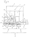
- a tape-dispensing textile machine 8 see Fig. 4
- a tape-dispensing textile machine 8 see Fig. 4
- a tape-dispensing textile machine 8 see Fig. 4
- a can magazine 6 into an empty can magazine 3 for feeding empty cans 2 (Empty cans) to the filling station 1 and a full-can magazine 4 for recording the cans 20 filled in the filling station 1 is divided.
- empty cans magazine 3 is one Feeder 30 assigned while feeding the filled cans 20 into the full-can magazine 4 by ejecting it from the filling station 1 is effected.
- FIGS. 1a to 1f In the starting situation shown in FIG. 1a, there is a can carrier 5 loaded with a predetermined number of empty cans 2 (empty cans) in the empty can magazine 3, while a further, but empty, can carrier 50 is available in the full can magazine 4.
- the empty cans 2 With the aid of the feed device 30, the empty cans 2 are brought down one after the other from the can carrier 5 into the area of the filling station 1 (see arrow f 1 in FIG. 1b). There the can 2 is filled with sliver. Subsequently, the former empty jug now reaches the jug carrier 50 provided in the full jug magazine 4 as a filled jug 20.
- FIG. 1b shows the point in time at which the can carrier 5 located in the empty can magazine 3 has been emptied and the can carrier 50 located in the full can magazine 4 has been loaded with the predetermined number of full cans 20.
- the can carrier 50 is picked up from the full-can magazine 4 (see arrow f 2 ) and fed to a belt-processing textile machine (not shown) for processing (FIG. 1c).
- the previously emptied can carrier 5 is then removed from the empty can magazine 3 (see arrow f3 in FIG. 1d) and fed to the full can magazine 4 (arrow f4 in FIG. 1e).
- a new can carrier 51 loaded with empty cans is placed in the empty can magazine 3 which has become empty in this way (see arrow f 5 in FIG. 1 f), as a result of which the initial situation according to FIG. 1 a is restored and the described work cycle of can start at the beginning.
- the can carriers 5, 10 are used a whole group of empty cans 2 is transported, simply into the empty can magazine 3 on the feed side of the filling station 1 the belt-dispensing textile machine 8 (Fig. 4) retracted and there during of the filling process.
- the operator remains physically very strenuous activities are spared, because they do not empty Cans 2 need to remove from the can carrier 5 to the empty can magazine 3 to feed, even later the filled cans 20 from the Vollkannenmagazin 4 must take out to 50 on the can carrier to turn off.
- the only one in the previously described version of the process the remaining work is the removal of can carriers 5, 50, 51 ... in the empty can magazine 3, the transfer of a cleared can carrier 5, 50, 51 ... from the empty can magazine 3 into the full can magazine 4 and the collection of such a can carrier 5, 50, 51 ... from the full can magazine 4.
- the transfer of an emptied can carrier 5 from the empty can magazine 3 into the full can magazine 4 can also be carried out without human intervention, as shown in FIG 4 in the direct way, that is to say transversely to the feed or pick-up direction (see arrows f 5 and f 2 in FIGS. 2d and 2e), the can carrier into which the full-can magazine 4 is placed.
- the means for this will be explained later with reference to FIGS. 3 and 4.
- the empty jug magazine has 3 except for a feed shelf 32 for the can carrier 5, of which the mentioned feeder 30 the empty cans 2 individually and thus one after the other according to the filling sequence of the filling station 1
- the full-can magazine 4 in turn has a receiving surface 40 and a buffer or Pick-up area 41.
- the filled ones delivered by the filling station 1 Cans 20 reach a provided on the receiving surface 40, first empty can carrier 50, which after loading the pick-up area 41 is fed where it is waiting for it to be picked up.
- the feed device 30 (see FIG. 1), which is designed in a manner known per se and can be arranged next to a can carrier or above a can carrier as required, now feeds an empty can 2 to the filling station 1 (arrow f 1 ) grips the can 2 in a manner known per se and transports it under a filling head (not shown). This is where the actual filling process takes place, after the completion of which the now filled can 20 is conveyed further and finally ejected from the filling station 1 onto the can carrier 50 which is available in the receiving position on the receiving shelf 40. In this way, the feed device 30 gradually feeds all empty cans 2 from the can carrier 5 to the filling station 1.
- the two middle shelves 32 and 40 which work together with the filling station 1, are again in the normal working state.
- the two outer shelves are not involved in the filling process and form buffer stations. It is therefore irrelevant when a new can carrier 52 with empty cans 2 is fed in here (see arrow f 5 in FIG. 2d) or when the can carrier 50 with the filled cans 20 is picked up (see arrow f 3 in FIG. 2e), as long as this happens in the period between two transfer offsets to be made. This can be done in a largely time-dependent decoupling from the filling process. It also does not matter whether this feeding or removal of can carriers is done manually by an operator or fully automatically using an automatic transport and transportation control device.
- a can changer 10 shown in Fig. 3 is only part of the filling station 1 (see Figs. 1 and 2) a can changer 10 shown.
- This has an arcuate Can guide 100, which substantially from the feed footprint 32 to to the filling head of the filling station 1, not shown.
- the can changer 10 also has a rotating driver arm 11, of which in FIG. 3 only the free one with the jug to be transported (see with dash-dotted Contoured can 2a) cooperating end see is.
- Another arcuate can guide 101 of the can changer 10 extends from the filling head to the receiving surface 40.
- Another can guide 102 is assigned to the receiving surface 40 and has the task of filling a can 20 coming from the filling head the circular path of the can changer 10 away in the direction of which on the To steer receiving surface 40 located can carrier 50.
- the above Can guides 100, 101 and 102 are below the work area of the rotating driving arm 11 arranged so that its Freedom of movement is not restricted.
- the can carrier 5, 50, 51, 52 ... can be designed in any suitable form be, for example as a pallet or the like. In the one shown in FIGS. 3 and 4 Exemplary embodiment takes place as a can carrier 5, 50, 51, 52 ... Can car application. This points at the can changer 10 opposite end on an upwardly extending handle 53, with the help of the can carrier 5, 50, 51, 52 ... (can car) an operator can be handled. From the handle 53 to The jug car (can carrier 5, 50, 51, 52 ...) a can footprint 54, which is laterally by two Guides 55 and 56 are limited to the cans 2 and 20 in series, respectively hold. The can footprint has between these guides 55 and 56 54 two or more support strips 540 and 541 to reduce the friction between the Jugs 2 and 20 and the jug cart (can carriers 5, 50, 51, 52 ...) to reduce.
- the described features of the can car are clearly recognizable with the can carrier 50 located on the receiving shelf 40.
- the car has two pairs of wheels 59 and on its underside 590, of which the pair of wheels 59 facing away from the handle bracket 53 is not is steerable or pivotable, while that arranged closer to the handle bar 53 Pair of wheels 590 steerable, d. H. the direction of movement of the car is adjustable by pivoting its bracket. Possibly can instead of one or the other pair of wheels 59 or 590 also apply a single role.
- the can magazine 6 has the length of a can carrier 5 at a distance, 50, 51, 52 ... each on its and the can changer 10 and a locking means on its side facing away from the can changer 10 forming guide 60 or 61 to the can carrier 5, 50, 51, 52 ... both on the feed shelf 32 and on the receiving shelf 40 to lock in a defined position with respect to the can changer 10.
- This securing of the 60 and 61 in the guide area can carriers 5, 50, 51, 52 ... is for error-free function when feeding empty cans 2 to can changer 10 as well important when dispensing filled cans 20 from the can changer 10.
- the can carriers 5, 50, 51, 52 ... are on each of the parking spaces (waiting space 31, feed footprint 32, pick-up footprint 40 and pick-up footprint 41) associated with further locking means 62, which can support 5, 50, 51, 52 ... across the can movement when feeding to the can changer 10 or when recording the dispenser 10 delivered Secure cans 20.
- These locking means 62 can be designed differently be like a comparison of the parking spaces (waiting space 31 and remaining spaces 32, 40 and 41) shows.
- these locking means 62 are formed in a wedge shape (prism shape), while the waiting area 31 on its feed side (i.e.
- the waiting area 31 has also a threshold 310, over which the designed as a can car Can carrier 51 must roll away when placed in its waiting position becomes. In this case, one that is provided on the underside of the can car arrives Guide pin 510 into a stationary wedge-shaped guide 311, which aligns the can carrier 51 exactly.
- the feed bracket 300 engages on the Filling station 1 facing away from the row of cans on the on the Feed shelf 32 deposited can carrier 5 is arranged, and pushes the cans 2 to the can changer 10 cyclically in coordination with the latter Work too.
- the feed bracket 300 takes over the described function of the wedge 33, so that there is no need for a separate element for this.
- a transfer device 7 is arranged below the bottom of the can carriers 5, 50, 51, 52 ...
- this essentially consists of a carriage or slide 70 which can be moved transversely to the feed or pick-up direction of the can carriers 5, 50, 51, 52 ... (see arrows f 5 and f 2 in FIGS . 2e) and a support surface 700 for receiving can carriers 5, 50, 51, 52 .... 3, the carriage 70 is connected to two drive pistons 71 which are connected to a medium supply and discharge line.
- a monitoring device 9 (FIG. 3) assigned, which determines whether the can carrier 5 located there cleared or whether there is still a jug 2 on it.
- the monitoring device 9 can be designed differently, e.g. B. as a figure that preset to the number of cans 2 on a can carrier 5 and with every can that passes this monitoring device, is reset by a value and when the value reaches zero reports this state to the control device 72.
- a simple light barrier 90 can be provided, which can be is interrupted until the last can 2 has left the can carrier 5, and then via line 900 a corresponding signal to the control device 72 issues.
- the light barrier 90 can instead of transversely to the can advance direction can also be provided in parallel, for example by the light source or photodiode delimiting the light barrier 90 on the feed bracket 300 and the counter element at a suitable location the side of the feed shelf 32 facing the filling station 1 is.
- the via line 720 with a control device of the tape dispenser Textile machine 8 related control device 72 is correct Work of the can magazine 6 on the work of the belt-dispensing textile machine 8 from. So can the feed device 30, in a manner not shown is connected to the control device 72 only in on the work of the can changer 10 work in a coordinated manner.
- the footprints of the can magazine 6 so designed and dimensioned that they offset all three can carriers 51, 5 and 50 at the same time.
- the support surface 700 of the carriage 70 extends over three adjacent parking spaces, d. H. about the width of a footprint reduced width of the total floor space. In the rest position shown the carriage 70 is in a lowered position, whereby the carrying surface 700 from the feed footprint 32 to over the pick-up footprint 41 extends.
- the control device 72 causes the drive pistons to be emptied 71, which is now in its lowered position below the Can carrier 5 and 50 located carriage 70 from a rest or Waiting position moved sideways by the width of a footprint until the Carriage 70 is under the can carriers 51, 5 and 50 and thus extends from the waiting position to the reception position including. In this position, which is reached by a monitoring device, not shown, e.g. B.
- the control device 72 can be signaled, the control device 72 causes the two Tubing 74 air or other gaseous or liquid fluid is fed.
- the hoses 74 thus fill, lifting the two in the process Rails 73 and thus also the carriage 70. With this lifting movement the carriage 70 takes itself in its area of extension located three can carriers 51, 5 and 50 and lifts them out the area of action of the stationary locking means (guide 311, positioning guides 620 and locking means 62).
- the carriage 70 can now in its Starting position are retracted, taking the ones he has taken with him Can carrier 51, 5 and 50 offset in such a way that now the can carrier 51 equipped with empty cans 2 in the feed position, the empty can holder 5 in the receiving position and the one with full cans 20 loaded can carriers 50 is in the collection position. After reaching its starting position, the carriage 70 is lowered again by the fluid is drained from the two tubes 74.
- the time of the very first was shown in FIG. 4 Start of work chosen, at which the people involved in the work through two shelves (feed shelf 32 and receiving shelf 40) Offset of the carriage or carriage 70 have been occupied and this still has not been lowered.
- the waiting position can already be new can carrier 51 can be reassigned, as shown in FIG. 4.
- Transfer of a can carrier 5, 50, 51, 52 ... from one position (Footprint) to the next can in principle be done in any way, and depending on the design of the jug magazine 6 individually or together with other can porters.
- both the method and the device can also be modified in many ways, in particular by exchanging individual characteristics with equivalents or with others Characteristic combinations.
- the transfer of the can carriers brings in a single direction with regard to the formation of the transfer device 7 special advantages, but is still not the only way for the transfer of can carriers 5 from one of the shelves the next to be filled in terms of the work cycle Floor space comes into question.
- So Fig. 6 shows an arrangement that is particularly close arrangement of adjacent filling stations 1 is preferable.
- the neighboring filling stations 1 are different belt-dispensing textile machines 8 (Fig. 4) belong or always in pairs Form part of a so-called double-head section.
- the work phase according to FIG. 6 corresponds to the work phase according to FIG. 2d).
- the empty cans 2 are with the help of a feed device, not shown 30 (see FIGS. 1 and 3) fed to the filling station 1 and arrive after the filling process as filled cans 20 on the in the receiving position can carriers 5.
- the can carrier 50 can be picked up from the pick-up area 41 in order to make it available for later use Release the can carrier 5 release. If the can carrier 5 is loaded, so he is from his recording position to the now vacant Pick-up space 41 transferred.
- the empty can carrier 51 is then moved from the feed shelf 32 to the receiving shelf 40 transferred. As a result, the feed footprint 32 is free, on which the can carrier 52 previously deposited on waiting area 31 is brought.
- the waiting area 31 is now available for receiving another, with empty Jugs of 2 filled can carriers ready.
- a can carrier 5, 50, 51, 52 ... For the transfer of a can carrier 5, 50, 51, 52 ... from one position to the next, for example, a not shown, height-adjustable carriage or carriage can be provided, on which there is another carriage or carriage, with the directions of movement of the superimposed carriages or sleds can be set at right angles to each other. If, for example, the lower carriage or carriage is movable transversely to the feed or pick-up movement of the can carriers 5, 50, 51, 52 ... (arrows f 5 and f 2 in FIGS. 1c and 1f), the upper carriage or carriage is can be moved in parallel.
- the can carriers 5, 50, 51, 52 ... can also be locked in such a way Training can be done in a similar manner as this is related 3 and 4 has been described (locking means 62, guides 60 and 61, locking means 75, threshold 310, guide 311, positioning guide 620).
- the locking means can also deviate from those previously described Be trained. It is possible instead of the can carrier to lift out of the sphere of action of the locking means Locking device from the range of motion of the can carrier for the duration the transfer movements or during delivery to the empty can magazine 3 or 3a or the collection from the full-can magazine 4 or 4a to move away from the range of motion of the can carrier (not shown).
- Carriage 70 instead of a height adjustment of the one shown in FIGS. 3 and 4 Carriage 70 or one suitable for a device according to FIG. 6 Alternatively, only a slide adjustment of the carrying surface 700 relative to the carriage 70 are provided, this height adjustment and also the slide drive by means of motors, racks etc. can be carried out.
- the transfer device 7 can also be formed elsewhere and in a different way.
- the transfer device 7 can also be formed elsewhere and in a different way.
- the transfer device 7 can also be formed elsewhere and in a different way.
- can carrier conveyor belts or - chains (not shown).
- Each of these can be guided by a belt or chain be guided and have one or more drivers, with its or whose help the can carriers are brought to the band or Chain movement to follow.
- a controllable clutch ensures the establishment or removal of the entrainment connection.
- the can carrier to be moved within the can magazine 6 5, 50, 51, 52 ... should always be lifted completely.
- this is not necessarily required.
- the other pair of wheels 590 (or the corresponding individual roller) can keep in contact with the ground and move in the direction of movement orient the can car and support the can car.
- the pot holder at both ends with one transport device each, for example one chain with grippers be detected and transferred essentially torque-free.
- the can carrier if all roles are steerable are not raised.
- the can carrier becomes raised at least at the end of the non-steerable rollers. Due to the essentially torque-free transport, the transport device can largely wear-resistant and especially light Execution can be designed.
- the can carriers 5, 50, 51, 52 ... in be formed in different ways. So, not least in Depending on the design and operation of the feeder 30, which the empty cans 2 also from that facing the filling station End of a can carrier can be cleared out without the entire row of cans to have to move u.
- U. special guide means (guides 55 and 56 - see Fig. 3) omitted. The same applies to those who reduce glide Means (support strips 540 and 541 - see Fig. 3) too, for example due to a particularly low-friction material, e.g. B. plastic, are formed. There may be no friction-reducing measures at all required, especially if the feed device empty cans 2 when they are fed to the can changer 10.
- the embodiment shown in Fig. 5 shows that it can make sense to have more buffer space for the two magazines (empty jug magazine 3 and full jug magazine 4) to be provided.
- Fig. 5 shows two successive filling stations 1 and 12, of which, for example, the first filling station is part of a first route (not shown) and the second filling station 12 is part of a second line 80.
- the first stretch with the filling station 1 forms a first stretch passage I
- the second stretch 80 forms a second stretch passage II.
- the Can magazine 6 of this second stretch passage II can be formed in this way be as previously explained with the aid of FIGS. 2 to 4.
- the first stretch passage I points as a buffer in its empty can magazine 3a a total of two waiting areas 31 and 31a and in their full can magazine 4a two pick-up shelves 41 and 41a.
- the second stretch 80 two can carriers 57 and 58 are always available at the same time.
- Allocate magazines to collect the can carriers in pairs. 5 is done differently by ensuring that the Line 80 the required can carriers 57 loaded with full cans 20 and 58 always supplied in pairs and accordingly also in pairs by her be discharged again. That from route 80 of the second stretch II delivered can carrier 582 and 583 thus go in pairs Empty can magazine 3a of the first stretch I where it is on the two Waiting areas 31 and 31a are parked.
- a can carrier after the other is then individually within the can magazine 6 by one Floor space transferred to the next one.
- the Can carrier collected and only when a pair is complete as Couple are forwarded again to the second stretch II.
- the two route passages I and II do not work synchronously. For this reason, as indicated in Fig. 5, between the distance of the first stretch I and stretch 80 of the second stretch II a distribution track 81 is arranged which enables can carriers as required from different sections of the first stretch I different Routes 80 of the second stretch passage II are fed can.
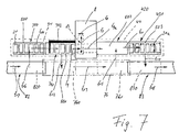
- FIG. 7 shows a further modification which is particularly suitable for feeding so-called flat or rectangular cans 21 to a filling station 13 and for providing such filled rectangular cans 21a for collection.
- the filling station 13 is designed in this embodiment in the usual way for flat or rectangular cans 21 such that the rectangular can 21 receives a traversing movement (see double arrow f 7 ) in the direction of its larger axis during filling, while this traversing movement is a pendulum movement (see double arrow f 8 ) is superimposed transversely to the traversing movement.
- the four shelves 340, 341, 420 and 421 of the two can magazines 34 and 42 are arranged essentially along a line in the exemplary embodiment shown.
- a transfer device 76 for example in the form of a conveyor belt, in the extension of which, in the exemplary embodiment shown, there is a can carrier feed path 82 on the feed side, while a can carrier discharge path 83 is located on the discharge side.
- Both the can carrier feed path 82 and the can carrier discharge path 83 can be designed such that the can carriers are automatically transported in a manner known per se;
- a path can also be provided in the form of a path without a special marking or design, along which an operator brings a can carrier 500 into a standby position 820 (see arrow f 17 ), from which it is transferred to the waiting area 340 after it is cleared what can be done in any way by the operator or an automatic device.
- a can carrier 503 provided for pick-up on the pick-up area 421 is suitably transferred from the pick-up area 421 into a pick-up standby position 830, from where it is picked up by the operator or a suitable transport device (e.g. self-driving car, etc.) (see Arrow f 18 ).
- the standby position can 820 are formed by the waiting area 340.
- a rectangular can 21 has been fed from a can carrier 501 located on the feed shelf 341 to the work area of the filling station 13 (see arrow f 9 ) and can be filled.
- the rectangular can 21 is given a traversing movement within the filling station 13 in a manner known per se (see double arrow f 7 ) and, if necessary, a pendulum movement is superimposed on this traversing movement (see arrow f 8 ).
- the rectangular can 21 is filled, it is pushed out of the filling station 13 in the direction of the arrow f 9a onto the can carrier 502, where the filled cans 21a are collected, by an ejection device (not shown) which is part of the filling station 13 or is assigned to it until the can carrier 502 is filled.
- the filling station 13 can also be arranged outside the transfer carriage. In this embodiment, another can changer is required.
- the can carrier 503 While the rectangular cans 21a to be placed on the can carrier 502 are being filled, the can carrier 503, which was loaded at an earlier point in time, is picked up from the pick-up area 421, where it is either transported directly from here or, if provided, is first transferred to the ready-to-pick-up position 830 (see arrow f 10 ).
- the pick-up area 421 is thus free for its reception.
- the can carrier 502 is now transferred from the receiving shelf 420 in the direction of arrow f 11 to the pick-up shelf 421 which has become free.
- the empty rectangular cans 21 located on the waiting shelf 340 can be transferred to the feed shelf 341 with the can carrier 500 (see arrow f 14 ). This happens during the time during which the last rectangular can 21 of the previously emptied can carrier 501 is still in the filling station 13, so that after the mentioned rectangular can 21 has been filled, a new rectangular can 21 - now from the can carrier 500 - of the filling station is immediately removed again 13 can be supplied.
- the previously emptied can carrier 501 is transferred from the waiting position 761 to the receiving shelf 421 (arrow f 15 ). This takes place during the time when the first rectangular can 21 of the can carrier 500 which has been moved inward is being filled, so that the filling station 13 can dispense the filled rectangular can 21 a to the can carrier 501 which has meanwhile been made available on the receiving shelf 420 without interrupting production.
- a new can carrier (not shown), which has meanwhile been provided in the ready position 820, is transferred from the ready position 820 to the waiting area 340 in the direction of arrow f 16 .
- the can carrier 500 to 503 from or into one of the mentioned Positions 820 or 830 or the placement of one of the can carriers one or the other of the shelves 340, 341, 420 or 421 can be in any Be solved constructively.
- the relative arrangement also plays a role of the shelves 340, 341, 420 or 421 and / or the provision of the Positions 820 and 830 are not essential. So are orders 1, 2, 5 or 6 also in connection with Flat or rectangular cans possible.
Landscapes
- Engineering & Computer Science (AREA)
- Mechanical Engineering (AREA)
- Textile Engineering (AREA)
- Spinning Or Twisting Of Yarns (AREA)
- Replacing, Conveying, And Pick-Finding For Filamentary Materials (AREA)
Applications Claiming Priority (2)
| Application Number | Priority Date | Filing Date | Title |
|---|---|---|---|
| DE19819376 | 1998-04-30 | ||
| DE19819376A DE19819376A1 (de) | 1998-04-30 | 1998-04-30 | Verfahren und Vorrichtung zum Zuführen und Abstellen von Kannen |
Publications (3)
| Publication Number | Publication Date |
|---|---|
| EP0953535A2 true EP0953535A2 (fr) | 1999-11-03 |
| EP0953535A3 EP0953535A3 (fr) | 2001-05-02 |
| EP0953535B1 EP0953535B1 (fr) | 2004-07-14 |
Family
ID=7866316
Family Applications (1)
| Application Number | Title | Priority Date | Filing Date |
|---|---|---|---|
| EP99102071A Expired - Lifetime EP0953535B1 (fr) | 1998-04-30 | 1999-02-02 | Procédé et appareil pour l'approvisionnement et le stockage de pots |
Country Status (3)
| Country | Link |
|---|---|
| US (2) | US6161257A (fr) |
| EP (1) | EP0953535B1 (fr) |
| DE (2) | DE19819376A1 (fr) |
Cited By (2)
| Publication number | Priority date | Publication date | Assignee | Title |
|---|---|---|---|---|
| CN102115924A (zh) * | 2011-04-06 | 2011-07-06 | 张家港市大成纺机有限公司 | 纺纱梳理机的换筒装置 |
| CN107337030A (zh) * | 2016-12-20 | 2017-11-10 | 大连大橡工程技术有限公司 | 锭子房自动化系统 |
Families Citing this family (2)
| Publication number | Priority date | Publication date | Assignee | Title |
|---|---|---|---|---|
| DE19819376A1 (de) * | 1998-04-30 | 1999-11-04 | Rieter Ingolstadt Spinnerei | Verfahren und Vorrichtung zum Zuführen und Abstellen von Kannen |
| US8746436B2 (en) * | 2012-10-04 | 2014-06-10 | Dyco, Inc. | Apparatus and method for separating articles susceptible to cohesive grouping |
Family Cites Families (14)
| Publication number | Priority date | Publication date | Assignee | Title |
|---|---|---|---|---|
| US3443287A (en) * | 1962-02-09 | 1969-05-13 | Schubert & Salzer Maschinen | Can changing in strand material handling |
| CH589556A5 (fr) * | 1974-12-24 | 1977-07-15 | Rieter Ag Maschf | |
| DE2543621C2 (de) * | 1975-09-30 | 1984-11-22 | Zinser Textilmaschinen Gmbh, 7333 Ebersbach | Kannenwechseleinrichtung |
| US5276947A (en) * | 1990-05-18 | 1994-01-11 | Schubert & Salzer Maschinenfabrik Ag | Device for the transportion of cans between machines or devices treating or processing fiber slivers |
| DE4212165A1 (de) * | 1992-04-10 | 1993-10-14 | Truetzschler Gmbh & Co Kg | Vorrichtung zum Fördern von Kannen auf der Einlaufseite von Spinnereimaschinen, z. B. Strecken |
| DE4233357B4 (de) * | 1992-10-05 | 2005-09-22 | Rieter Ingolstadt Spinnereimaschinenbau Ag | Verfahren zum Wechseln und Vorrichtung zum Magazinieren und Wechseln von Spinnkannen |
| JP3490498B2 (ja) * | 1993-05-14 | 2004-01-26 | ツリュツラー ゲゼルシャフト ミット ベシュレンクテル ハフツング ウント コンパニー コマンディトゲゼルシャフト | 紡績機械で縦長断面のケンスにスライバを充填する装置 |
| US5634316A (en) * | 1994-04-02 | 1997-06-03 | Trutzschler Gmbh & Co. Kg | Method and apparatus for handling flat coiler cans before, during and after filling the cans by a sliver-producing textile machine |
| DE4429254C2 (de) * | 1994-08-18 | 2003-12-24 | Saurer Gmbh & Co Kg | Faserbandkannentransportersystem |
| DE19509928A1 (de) * | 1995-03-18 | 1996-09-19 | Truetzschler Gmbh & Co Kg | Vorrichtung an einer Spinnereimaschine, z. B. Karde, Strecke, zum Fördern und Bereitstellen von Spinnkannen |
| DE19521185A1 (de) * | 1995-06-10 | 1996-12-12 | Truetzschler Gmbh & Co Kg | Kannenfördersystem zwischen zwei Strecken |
| DE19525737A1 (de) * | 1995-07-14 | 1997-01-16 | Schlafhorst & Co W | Kannenspeicher für Rechteck-Spinnkannen an einer Kannenfüllstation |
| DE19720829B4 (de) * | 1996-07-11 | 2010-06-17 | TRüTZSCHLER GMBH & CO. KG | Vorrichtung für eine Spinnkanne auf einem rotierbaren Kannenteller an einer Spinnereivorbereitungsmaschine, z. B. Strecke, Karde |
| DE19819376A1 (de) * | 1998-04-30 | 1999-11-04 | Rieter Ingolstadt Spinnerei | Verfahren und Vorrichtung zum Zuführen und Abstellen von Kannen |
-
1998
- 1998-04-30 DE DE19819376A patent/DE19819376A1/de not_active Withdrawn
-
1999
- 1999-02-02 DE DE59909932T patent/DE59909932D1/de not_active Expired - Fee Related
- 1999-02-02 EP EP99102071A patent/EP0953535B1/fr not_active Expired - Lifetime
- 1999-04-13 US US09/290,810 patent/US6161257A/en not_active Expired - Fee Related
-
2000
- 2000-12-19 US US09/741,500 patent/US6336258B2/en not_active Expired - Fee Related
Cited By (2)
| Publication number | Priority date | Publication date | Assignee | Title |
|---|---|---|---|---|
| CN102115924A (zh) * | 2011-04-06 | 2011-07-06 | 张家港市大成纺机有限公司 | 纺纱梳理机的换筒装置 |
| CN107337030A (zh) * | 2016-12-20 | 2017-11-10 | 大连大橡工程技术有限公司 | 锭子房自动化系统 |
Also Published As
| Publication number | Publication date |
|---|---|
| US6161257A (en) | 2000-12-19 |
| DE19819376A1 (de) | 1999-11-04 |
| US6336258B2 (en) | 2002-01-08 |
| US20010002503A1 (en) | 2001-06-07 |
| DE59909932D1 (de) | 2004-08-19 |
| EP0953535A3 (fr) | 2001-05-02 |
| EP0953535B1 (fr) | 2004-07-14 |
Similar Documents
| Publication | Publication Date | Title |
|---|---|---|
| EP0407703B1 (fr) | Procédé et dispositif pour stocker et déstocker des caissons contenant des matériaux en forme de bâton ou de plaque dans un magasin à rayonnage | |
| EP0452978B1 (fr) | Métier à filer | |
| DE4117434A1 (de) | Verfahren und vorrichtung zum stapeln | |
| DE3518906C2 (de) | Kopsladevorrichtung in einer Kopstransportvorrichtung für den Kopstransport von einer Spinnmaschine zu einem Spulautomaten | |
| DE19636470C2 (de) | Vorrichtung zum Handhaben von Glasscheiben | |
| DE2543621A1 (de) | Kannenwechseleinrichtung | |
| CH662586A5 (de) | Spinnanlage zur herstellung von garn aus vorgarn. | |
| DE3505495A1 (de) | Verfahren und vorrichtung zum austauschen leerer kannen gegen mit faserband gefuellte kannen | |
| DE4013066C2 (de) | Spulenwechselvorrichtung | |
| DE4323726A1 (de) | Transportfahrzeug für Faserbandkannen | |
| EP1098017A2 (fr) | Transporteur pour le transfert de pots de filature | |
| EP0198260B1 (fr) | Procédé et dispositif pour le transport et le stockage de bobines, par exemple pour l'alimentation des machines à filer | |
| DE4446449B4 (de) | Vorrichtung zum Zuführen von Spulen | |
| EP0953535B1 (fr) | Procédé et appareil pour l'approvisionnement et le stockage de pots | |
| DE2842432C2 (de) | Vorrichtung zum geordneten Ablegen von Kreuzspulen | |
| EP0877107B2 (fr) | Procédé et appareil pour le transport d'un groupe de pots | |
| DE102005002532A1 (de) | Vorrichtung und Verfahren zum automatisierten und zeitgleichen Bereitstellen und Wechseln von mindestens zwei Rollen aus Papierbahnen oder dergleichen für einen nachgeordneten Formatschneider | |
| CH677655A5 (fr) | ||
| DE1685614B2 (de) | Verfahren und vorrichtung zum kannenwechseln bei faserband abliefernden textilmaschinen | |
| DE3413157C1 (de) | Verfahren und Vorrichtung zum rechnergesteuerten Zusammenstellen von Warensendungen | |
| DE4432634A1 (de) | Kannenlose Vorgarnhandhabung | |
| EP0737642A2 (fr) | Machine de frisage | |
| DE68909831T2 (de) | Verfahren zum Transport von Vorgarnspulen, bei dem das Vorgarn vorher in eine bestimmte Lage gebracht wurde. | |
| DE4029894A1 (de) | Spulmaschine, die von hand mit ablaufspulen beschickt werden kann | |
| DE4142790C2 (de) | Kopstransporteinrichtung in einem Spulautomaten |
Legal Events
| Date | Code | Title | Description |
|---|---|---|---|
| PUAI | Public reference made under article 153(3) epc to a published international application that has entered the european phase |
Free format text: ORIGINAL CODE: 0009012 |
|
| AK | Designated contracting states |
Kind code of ref document: A2 Designated state(s): DE FR IT |
|
| AX | Request for extension of the european patent |
Free format text: AL;LT;LV;MK;RO;SI |
|
| PUAL | Search report despatched |
Free format text: ORIGINAL CODE: 0009013 |
|
| AK | Designated contracting states |
Kind code of ref document: A3 Designated state(s): AT BE CH CY DE DK ES FI FR GB GR IE IT LI LU MC NL PT SE |
|
| AX | Request for extension of the european patent |
Free format text: AL;LT;LV;MK;RO;SI |
|
| 17P | Request for examination filed |
Effective date: 20010518 |
|
| AKX | Designation fees paid |
Free format text: DE FR IT |
|
| 17Q | First examination report despatched |
Effective date: 20021219 |
|
| GRAP | Despatch of communication of intention to grant a patent |
Free format text: ORIGINAL CODE: EPIDOSNIGR1 |
|
| GRAS | Grant fee paid |
Free format text: ORIGINAL CODE: EPIDOSNIGR3 |
|
| RIN1 | Information on inventor provided before grant (corrected) |
Inventor name: PETER, CARSTEN Inventor name: KOVACS, OTMAR Inventor name: UEDING, MICHAEL |
|
| GRAA | (expected) grant |
Free format text: ORIGINAL CODE: 0009210 |
|
| AK | Designated contracting states |
Kind code of ref document: B1 Designated state(s): DE FR IT |
|
| REF | Corresponds to: |
Ref document number: 59909932 Country of ref document: DE Date of ref document: 20040819 Kind code of ref document: P |
|
| ET | Fr: translation filed | ||
| PLBE | No opposition filed within time limit |
Free format text: ORIGINAL CODE: 0009261 |
|
| STAA | Information on the status of an ep patent application or granted ep patent |
Free format text: STATUS: NO OPPOSITION FILED WITHIN TIME LIMIT |
|
| 26N | No opposition filed |
Effective date: 20050415 |
|
| PG25 | Lapsed in a contracting state [announced via postgrant information from national office to epo] |
Ref country code: FR Free format text: LAPSE BECAUSE OF NON-PAYMENT OF DUE FEES Effective date: 20051031 |
|
| REG | Reference to a national code |
Ref country code: FR Ref legal event code: ST Effective date: 20051031 |
|
| PGFP | Annual fee paid to national office [announced via postgrant information from national office to epo] |
Ref country code: IT Payment date: 20060228 Year of fee payment: 8 |
|
| PGFP | Annual fee paid to national office [announced via postgrant information from national office to epo] |
Ref country code: DE Payment date: 20060306 Year of fee payment: 8 |
|
| PG25 | Lapsed in a contracting state [announced via postgrant information from national office to epo] |
Ref country code: DE Free format text: LAPSE BECAUSE OF NON-PAYMENT OF DUE FEES Effective date: 20070901 |
|
| PG25 | Lapsed in a contracting state [announced via postgrant information from national office to epo] |
Ref country code: IT Free format text: LAPSE BECAUSE OF NON-PAYMENT OF DUE FEES Effective date: 20070202 |