EP0953537A2 - Lastmesssensor für eine Aufzugskabine - Google Patents
Lastmesssensor für eine Aufzugskabine Download PDFInfo
- Publication number
- EP0953537A2 EP0953537A2 EP99107382A EP99107382A EP0953537A2 EP 0953537 A2 EP0953537 A2 EP 0953537A2 EP 99107382 A EP99107382 A EP 99107382A EP 99107382 A EP99107382 A EP 99107382A EP 0953537 A2 EP0953537 A2 EP 0953537A2
- Authority
- EP
- European Patent Office
- Prior art keywords
- cage
- load
- detector
- shaft
- change
- Prior art date
- Legal status (The legal status is an assumption and is not a legal conclusion. Google has not performed a legal analysis and makes no representation as to the accuracy of the status listed.)
- Granted
Links
Images






Classifications
-
- B—PERFORMING OPERATIONS; TRANSPORTING
- B66—HOISTING; LIFTING; HAULING
- B66B—ELEVATORS; ESCALATORS OR MOVING WALKWAYS
- B66B1/00—Control systems of elevators in general
-
- B—PERFORMING OPERATIONS; TRANSPORTING
- B66—HOISTING; LIFTING; HAULING
- B66B—ELEVATORS; ESCALATORS OR MOVING WALKWAYS
- B66B1/00—Control systems of elevators in general
- B66B1/34—Details, e.g. call counting devices, data transmission from car to control system, devices giving information to the control system
- B66B1/3476—Load weighing or car passenger counting devices
-
- B—PERFORMING OPERATIONS; TRANSPORTING
- B66—HOISTING; LIFTING; HAULING
- B66B—ELEVATORS; ESCALATORS OR MOVING WALKWAYS
- B66B7/00—Other common features of elevators
Definitions
- the present invention relates to a load detector for an elevator cage.
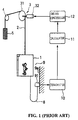
- An ordinary traction type elevator is composed as shown in FIG. 1 and FIG. 2.
- one terminal of a cable 2 is connected to a cage 1 and the other terminal of the cable 2 is connected to a counter weight via a sheave 31 of a hoisting machine 3 and deflector sheave 4.
- the hoisting machine is composed of the sheave 31 and a motor 32.
- the sheave 31 is driven by the motor 32, and the cable 2 is driven by the traction between the sheave 31 and the cable 2.
- the cage 1 is moved up and down via the cable 2.
- the cage 1 moves up and down along guide rails 7 by means of guide devices 6 attached to the cage 1.
- the cage 1 is composed of a cage frame 1A including a crosshead 1Aa, an upright 1Ab and a plank 1Ac, and a cab 1B mounted in the cage frame 1A. That is, construction of the cage 1 is in effect doubled by providing the cage frame 1A around the cab 1B, and the cab 1B is supported by vibration-proof materials 1C such as a rubber.
- the vibration-proof materials 1C reduce vibration transfer from the cage frame 1A to the cab 1B and improve passenger comfort during travel of the cage 1.
- a deformation detector 1D is installed between the cage frame 1A and the cab 1B.
- the vibration-proof materials 1C is pressed by the load of the cab 1B, and the amount of the deformation of the vibration-proof materials 1C is detected by the deformation detector 1D.
- the amount of the deformation is transmitted to a calculator 11 in an elevator control panel via a transmitting cable 8, a connector box 91 attached on a shaft wall 9a of a shaft 9, and a transmitter 10.
- the calculator 11 calculates the load of the cab 1B or the load of passengers on the basis of the amount of the deformation from the deformation detector 1D.
- the calculator 11 also calculates a necessary torque to drive the motor 32 so as to move the cage 1 smoothly at the start time, and outputs the torque signal to a drive controller 12. Accordingly, even if the cage 1 is filled with many passengers, the cage 1 does not move down suddenly at the start time when a brake is off. On the other hand, even if the cage 1 has no passengers, the cage 1 does not move up suddenly at the start time. That is, the drive controller 12 applies a necessary torque to the motor 32 before the brake is off so as to move the cage 1 smoothly at the start time.
- both the cage frame 1A and the cab 1B need a proper strength. It is not easy for the cage 1 to meet both the requirements of the proper strength and the capacity of the cab 1B.
- the deformation detector 1D can not be installed between the cage frame 1A and the cab 1B.
- the elevator has difficulty in controlling the torque applied to the motor 32 at the start time in accordance with change in the load.
- one object of the invention is to provide a load detector for an elevator which can detect the passenger load, even if a cab is integrated with a cage frame.
- a new and improved load detector for an elevator having a cage moving up and down in a shaft for transporting passengers, and a cable supporting the cage, including a relative position detector configured to detect a relative position of the cage against the shaft; and a calculator configured to calculate a change of the relative position between the position of the cage just after landing at a floor and the position of the cage just before leaving the floor, and a load of the cage on the basis of the change of the relative position caused by an expansion and contraction of the cable.
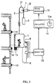
- FIG. 3 shows a load detector for an elevator cage of a first embodiment of the present invention.
- a cage 1 for passengers moves up and down by the movement of a cable 2.
- the cage 1 has a optical position sensor 13.
- Reflecting plates 14 are attached on a shaft 9 near each floor level and arranged to face the optical position sensor 13 at the time the cage 1 lands at the floor.
- a relative position detector is composed of the optical position sensor 13 and the reflecting plate 14.
- the position sensor 13, as shown in FIG. 4, is composed of a light source 132 in a box 131 for irradiating a light with a predetermined wavelength toward the reflecting plates 14, a lens 134 in the box 131 for gathering a reflected light from one of the reflecting plates 14, and photoconductive cells such as PSD (Position Sensitive Device) elements 133 arranged in the moving direction of the cage.
- PSD elements 133 transforms a gathered light from the lens 134 into a voltage signal, and the PSD elements 133 are arranged to output respective different voltage signals in accordance with the position of the cage 1.
- the voltages produced by the PSD elements 133 of optical position sensor 13 also shift up or down.
- a relative position of the cage 1 against the reflecting plate 14 on the shaft 9 changes and the voltage signals from the PSD elements 133 also change on the basis of the relative position of the cage 1 against the reflecting plate 14.
- the voltage signals are transmitted to a filter 135 in order to extract and output a constituent signal corresponding to the light with the predetermined wavelength. That is, the filter 135 eliminates noise from the voltage signals.
- the constituent signal is transmitted to a transmitter 10 via a cable 8 and a connector box 91 on a shaft wall 9a.
- a field of vision of the lens 134 is set greater than a field of reflected light from the reflecting plate 14. Reflected light from the shaft wall 9a except the reflected light from the reflecting plate 14 is scattered and is not detected by the PSD elements 133 effectively.
- the calculator 11 When the cage 1 lands on a floor level, the voltage signals from the PSD elements are outputted corresponding to the vertical position of the cage 1 and transmitted to a calculator 11 via the transmitter 10.
- the calculator 11 has a timer 11a and manages the voltage signals in order of the input time.
- the calculator 11 calculates a passed time after closing a cage door, if there is no call, i.e., either a destination call or a hall call.
- the destination call is a call by which passengers order the destination in the cage 1
- the hall call is a call by which passengers call the cage 1 to a floor. If the passed time exceeds a predetermined time and the cage 1 does not move during the passed time, the calculator 11 resets a load value to zero on the assumption that there is no passenger in the cage 1.
- the cage 1 goes up or down and lands at the destination floor.
- the operation of detecting a load of cage 1 is as follows.
- the optical position sensor 13 detects the reflecting plate 14 of the destination floor. Before the cage door opens, the relative position Yb of the cage 1 against the reflecting plate 14 is detected by the optical position sensor 13. At this time, the cage 1 stops at the landing floor, because the sheave 31 is locked by a brake device (not shown). However, since the cable 2 itself has elasticity, the cable 2 expands and contracts corresponding to a load change of the cage 1. As a result, the vertical position of the cage 1 changes, even if the cage 1 lands and stops on the floor. Consequently, when passengers finish getting on and off, the vertical position of the cage 1 could change corresponding to the load change of the cage 1.
- the optical position sensor 13 detects the relative position Ya of the cage 1 against the reflecting plate 14.
- the calculator 11 calculates the current load Mn of the cage 1 on the basis of the relative positions Ya and Yb, an elastic coefficient k of the cable 2, and the previous load Mo of the cage 1, and the current load Mn is calculated as follows.
- Mn Mo + k x (Yb - Ya)
- the elastic coefficient k can be changed corresponding to the vertical position of the cage 1. Because the length of the cable 2 between the sheave 31 and the cage 1 changes corresponding to the vertical position of the cage 1. Therefore, the elastic coefficient k is applied corresponding to location of the cage 1.
- the calculator 11 calculates a necessary torque to drive the motor 32 so as to start the cage 1 smoothly on the basis of the load Mn, and outputs the torque signal to a drive controller 12.
- a load of the cage 1 can be calculated on the basis of the difference of the relative position of the cage 1 against the shaft wall 9a, between a vertical position of the cage 1 just after landing at a floor and a vertical position of the cage 1 just before leaving the floor. Further, if the no call time exceeds a predetermined time and the cage 1 does not move for the no call time, the calculator 11 resets the load value to zero indicating that there is no passenger in the cage 1. Therefore, a cumulative error of a load of the cage 1 can be automatically adjusted.
- the load detector can be used as a landing position detector of the cage 1. Moreover, since the optical position sensor 13 detects the relative position of the cage 1 against the reflecting plate 14 without mechanical contact and the filter 135 eliminates noise due to other light sources, the precision of the load detector can be improved.
- the optical position sensor 13 and the reflecting plate 14 can be changed.
- a camera having an image sensor which can recognize light and shade can be substituted for the position sensor 13 and a plate having a geometric or other pattern can be substituted for reflecting plate.
- the camera can then be provided with an image processor (not shown) to recognize an image of the geometric or other pattern, or a portion of this pattern, picked up by the camera, and output different signals corresponding to the position of the cage 1.
- FIG. 5 shows a load detector of the second embodiment of the present invention.
- a potential meter 15 is attached to the bottom of the cage 1.
- the potential meter 15 is composed of a slide shaft 151 moving in the axial direction of a cylinder 152.
- a roller 153 is attached to the end of the slide shaft 151.
- the roller 153 rotates in the moving direction of the cage 1.
- a spring 154 is inserted between the roller 153 and the cylinder 152 so that the roller 153 is always forced toward the shaft wall 9a.
- Slopes 16 are secured on the shaft wall 9a near all floor levels. Each slope 16 has an inclined plane 16a as shown in FIG. 5. The roller 153 is to pass the floor level contacting the inclined plane 16a.
- the slide shaft 151 is forced toward the shaft wall 9a by the spring 154, if the cage 1 moves up and down, the roller 153 rolls on the slope 16, and the slide shaft 151 slides in axial direction of the cylinder 152.
- the potential meter 15 outputs voltage signals corresponding to a position of the slide shaft 151, and the voltage signals are transmitted to the transmitter 10 via the transmitting cable 8.
- the cage 1 goes up or down and lands at the destination floor.
- the operation of detecting a load of cage 1 is as follows.
- the roller 153 contacts the slope 16.
- the relative position Yb of the cage 1 against the shaft wall 9a is detected by the potential meter 15.
- the cage 1 stops at the landing floor, because the sheave 31 is locked by a brake device (not shown).
- the cable 2 itself has elasticity, the cable 2 expands and contracts corresponding to a load change of the cage 1.
- the vertical position of the cage 1 changes, even if the cage 1 lands and stops at the floor. Consequently, when passengers finish getting on and off, the vertical position of the cage 1 could change corresponding to a load change of the cage 1.
- the potential meter 15 detects the relative position Ya of the cage 1 against the shaft wall 9a.
- the calculator 11 then calculates the current load Mn of the cage 1 on the basis of the relative positions Ya and Yb, an elastic coefficient k of the cable 2, and the previous load Mo of the cage 1 in the same way as the first embodiment.
- a load of the cage 1 can be calculated on the basis of the difference of the relative position of the cage 1 against the shaft wall 9a, between the vertical position of the cage 1 just after landing a floor and the vertical position of the cage 1 just before leaving the floor.
- FIG. 6 shows a load detector for an elevator cage of a third embodiment of the present invention.
- an optical position sensor 17 is attached to the bottom of the cage 1.
- Slopes 18 are secured on the shaft wall 9a near all floor levels.
- Each slope 18 has a number of tiers and a triangular cross section as shown in FIG. 6.
- the horizontal width of each tier is different from another. That is, the horizontal width of the tiers are formed to be gradually changed in the moving direction of the cage 1.
- the optical position sensor 17 detects a distance from the cage 1 to the tiers of slopes 18.
- the optical position sensor 17 is composed of a pulse laser device and a distance detector.
- the pulse laser device irradiates a pulse laser light toward the tiers of slopes 18.
- the pulse laser light has a relatively narrow beam width, that is, the pulse laser light is not easily scattered.
- the distance detector detects a reflected laser light from the tiers of the slopes 18 and calculates a distance from the cage 1 to the tiers of the slopes 18.
- the optical position sensor 17 outputs voltage signals corresponding to a distance from the cage 1 to the tiers of the slopes 18, and the voltage signals are transmitted to the transmitter 10 via the transmitting cable 8.
- the vertical position change of the cage 1 is read by a change of a distance from the cage 1 to the tiers of the slopes 18.
- a load of the cage 1 can be detected in the same way as the second embodiment. Further, since the load of the cage 1 is detected by the optical position sensor 17 with no contact with the slopes 18, error due to frictional wear can be avoided and a durable detector can be obtained.
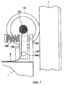
- FIG. 7 shows a load detector for an elevator cage of the fourth embodiment of the present invention, in which the load detector detects a load of the cage by detecting an angle change of a roller rolling on a guide rail in accordance with the movement of the cage 1.
- a disk roller 192 is secured to the upper base 191 of the cage 1 and rolls on a guide rail 7 in accordance with the movement of the cage 1.
- All angle detector 193 is arranged to an axis of the disk roller 192.
- the angle detector 193 is attached to one end of a lever 194, the other end of the lever 194 is pivotably secured to a fulcrum 194a of the base 191.
- a pole 195 stands on the base and passes through the lever 194.
- a spring 196 is arranged between one end of the pole 195 and the lever 194 so that the spring 196 pushes the lever 194 toward the guide rail 7 at any time.
- the disk roller 192 is pushed with the righting moment of the spring 196 and rolls on the guide rail 7.
- the angle detector 193 rotates as well.
- an angle change of the disk roller 192 is detected by the angle detector 193.
- the output signal of the angle detector 193 is transmitted to the calculator 11 via the transmitting cable 8 and the transmitter 10.
- the calculator 193 calculates a vertical position change of the cage 1 on the basis of the radius of the disk roller 192 and the angle change of the disk roller 192.
- a load of the cage 1 can be detected in the same way as the second embodiment. Further, since the calculator 193 is provided with an angular information from the angle detector 193 in accordance with a speed of the cage 1, the calculator 193 can calculate a speed of the cage 1 on the basis of time-differentiating the angular information. If a speed of the motor 32 is controlled by comparing the speed of the cage 1 with the predetermined velocity pattern, the hoisting machine 3 can be extremely precise.
- FIG. 8 shows a load detector for an elevator cage of the fifth embodiment of the present invention, in which the load detector has two position sensors such as the potential meter 15 in FIG. 5, attached to the bottom of the cage 1, so as to correct an error caused by an inclination of the cage 1 and to calculate a load of the cage 1 precisely.
- two potential meters 15A and 15B are attached to the bottom edges of the cage 1 symmetrically.
- Rollers 153A and 153B are respectively arranged to face toward the shaft wall 9a, and slide shafts 151A and 151B are respectively arranged to the same horizontal plane. Further, slopes 16A and 16B are secured on the shaft wall 9a near all floor levels. Each slope 16 has the same inclined plane as the FIG. 5. Output signals of the potential meters 15A and 15B are transmitted to the transmitter 10 via a calculator 20.
- the potential meters 15A and 15B respectively detect horizontal changes of the slide shafts 151A and 151B and respectively output voltage signals.
- the calculator 20 averages these voltage signals and transmits an averages signal to the transmitter 10.
- two potential meters 15A and 15B are attached to the bottom edges of the cage 1 symmetrically, and output signals of the potential meters 15A and 15B are averages. Therefore, even if the cage 1 inclines due to a biased load in the cage 1, a vertical position change of the cage 1 can be detected properly. As a result, the load detector can be precise.
- two potential meters 15A and 15B are applied to the position sensor.
- the optical position sensor 17 in FIG. 6 can be substituted for the potential meters 15A and 15B.
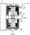
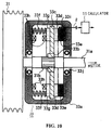
- FIG. 9 and FIG. 10 are sectional views of a brake showing a load detector for an elevator cage of the sixth embodiment of the present invention.
- a brake 33 is secured to a rotary shaft 31a between the sheave 31 and the motor 32 (not shown in FIG. 9).
- a sheave gear 31b having teeth on the surface is secured to the rotary shaft 31a in a housing 33a of the brake 33.
- a disk gear 33b meshes with the sheave gear 31b slidably in an axis direction.
- a brake disk 33c is secured to the surface of the disk gear 33b.
- a ring-shaped brake shoe 33d is attached to an inside wall of the housing 33a of the brake 33.
- a ring-shaped elastic ring 33e lies between the brake shoe 33d and the inside wall of the housing 33a.
- a brake shoe 33g is attached to the other inside wall of the housing 33a via springs 33f.
- Electromagnets 33h are arranged between the brake shoe 33g and the inside wall of the housing 33a. Furthermore, a strain gage 33i is attached on the surface of the elastic ring 33e. Bearings 33j are secured between the housing 33a and the rotary shaft 31a. All output signal of the strain gage 33i is transmitted to the calculator 11.
- a load of the cage 1 is applied to the rotary shaft 31a via the sheave 31. If a weight unbalance between the cage 1 and the counter weight 5 occurs due to a load change of the cage 1, a torsion force is applied to the sheave 31 corresponding to the weight imbalance, and the surface of the elastic ring 33e is pushed by the brake disk 33c connected to the sheave 31. As a result, the strain gage 33i outputs a voltage signal corresponding to a torsion force applied to the elastic ring 33e. The voltage signal is transmitted to the calculator 11. The calculator 11 calculates a torsion torque change of the sheave 31 on the basis of the voltage signal from the strain gage 33i, and calculates a load change of the cage 1 on the basis of the torsion torque.
- a load change of the cage 1 is calculated by calculating a torsion torque change of the sheave 31 locked by the brake 33. As a result, a load of the cage 1 can be obtained on the basis of a load change of the cage 1.
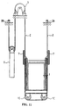
- FIG. 11 is a side view of a traction type elevator having hanging sheaves.
- the cage 1 has a "single" construction, that is to say, the cab is integrated with the cage frame.
- One end of the cable 2 is secured to a hitch 2B at an upper portion of the shaft 9.
- the other end of the cable 2 is secured to a hitch 2A via the counter weight 5, the hoisting machine 3, and hanging sheaves 1C of the cage 1.
- the cable 2 is driven by the hoisting machine 3, and the cage 1 and the counter weight 5 relatively move up and down.
- a tension F1 corresponding to a load of the cage 1 is applied to a shaft 1Ca of the hanging sheave 1C.
- a change of the tension F1 corresponds to a load change of the cage 1. Consequently, a change of a force F2 applied to the shaft 1Ca corresponds to a load change of the cage 1.
- FIG. 13 is a sectional view of a hanging sheave showing a load detector for an elevator cage of a seventh embodiment of the present invention, in which the load detector detects a change of the force F2 applied to the shaft 1Ca by means of a strain gage .
- the shaft 1Ca (only one is shown) is rotatably secured to the cage 1 via a bearing 1Cc, and the shaft 1Ca is supported by support members 1Cd on the cage 1.
- Strain gages 1Ce are built in the shaft 1Ca near the bearing 1Cc so as to detect a strain caused by a force F2 applied to the rotary shaft via the bearing 1Cc.
- Output signals of the strain gages 1Ce are transmitted to the calculator 11 via the transmitting cable 8 shown in FIG. 1.
- the calculator 11 calculates a load change of the cage 1 on the basis of a change of a force F2 applied to the shaft 1Ca, and then calculates a load of the cage 1.
- the calculator 11 calculates a necessary torque to drive the motor 32 so as to start the cage 1 smoothly on the basis of the load of the cage 1.
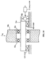
- FIG. 14 is a sectional view of a rotary shaft showing a load detector for an elevator cage of an eighth embodiment of the present invention.
- a load of the cage 1 is calculated on the basis of a force F2 applied to the shaft 1Ca and detected by the strain gages 1Ce built in the shaft 1Ca, while in FIG. 14, a load of the cage 1 is calculated on the basis of a strain of elastic members 1Cf lying between the shaft 1Ca and the cage 1 instead of the support members 1Cd in FIG. 13.
- a force F2 is applied to the cage 1 via the bearing 1Cc, the shaft 1Ca and the elastic members 1Cf.
- the elastic members 1Cf deforms by a load change of the cage 1.
- the deformation of the elastic members 1Cf is detected by a potential meter 1Cg, i.e., a differential transformer which transforms displacement into electric resistance, attached in parallel to one of the elastic members 1Cf. All output signal of the potential meter 1Cg is transmitted to the calculator 11 via the transmitting cable 8.
- the calculator 11 calculates a load change of the cage 1 on the basis of a change of a force F2 applied to the shaft 1Ca, and then calculates a load of the cage 1. Finally, the calculator 11 calculates a necessary torque to drive the motor 32 so as to start the cage 1 smoothly on the basis of the load of the cage 1.
- a load detector is installed at the hanging sheave 1C, a load of the cage 1 is detected precisely.
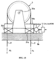
- FIG. 15 is a side view of a sheave showing a load detector for an elevator cage of a ninth embodiment of the present invention.
- the hoisting machine 3 is arranged on a shaft ceiling wall 9b via two elastic members 31c.
- a potential meter 31d is attached in parallel to one of the elastic members 31c.
- the potential meter 31d outputs a voltage signal corresponding to a deformation of the elastic member 31c.
- An output signal of the potential meter 31d is transmitted to the calculator 11 via the transmitting cable 8.
- a force F3 applied to the rotary shaft 31a of the sheave 31 is based on the sum of a load of the cage 1, a load of the counter weight, a load of the cable 2 and a load of the hoisting machine 3. Above all, the load of the cage 1 is the only item to be changeable.
- a load change of the cage 1 is calculated on the basis of a deformation of the elastic member 31c detected by the potential meter 31d.
- the calculator 11 calculates a load of the cage 1 on the basis of the load change of the cage 1.
- the calculator 11 calculates a necessary torque to drive the motor 32 so as to start the cage 1 smoothly on the basis of the load of the cage 1.
Landscapes
- Engineering & Computer Science (AREA)
- Automation & Control Theory (AREA)
- Mechanical Engineering (AREA)
- Computer Networks & Wireless Communication (AREA)
- Elevator Control (AREA)
- Indicating And Signalling Devices For Elevators (AREA)
- Maintenance And Inspection Apparatuses For Elevators (AREA)
- Cage And Drive Apparatuses For Elevators (AREA)
Priority Applications (1)
| Application Number | Priority Date | Filing Date | Title |
|---|---|---|---|
| EP03003118A EP1314675B1 (de) | 1998-04-28 | 1999-04-23 | Messung der Last in einer Aufzugskabine |
Applications Claiming Priority (2)
| Application Number | Priority Date | Filing Date | Title |
|---|---|---|---|
| JP10119495A JPH11314868A (ja) | 1998-04-28 | 1998-04-28 | 昇降機のかご荷重検出装置 |
| JP11949598 | 1998-04-28 |
Related Child Applications (1)
| Application Number | Title | Priority Date | Filing Date |
|---|---|---|---|
| EP03003118A Division EP1314675B1 (de) | 1998-04-28 | 1999-04-23 | Messung der Last in einer Aufzugskabine |
Publications (3)
| Publication Number | Publication Date |
|---|---|
| EP0953537A2 true EP0953537A2 (de) | 1999-11-03 |
| EP0953537A3 EP0953537A3 (de) | 2002-03-13 |
| EP0953537B1 EP0953537B1 (de) | 2004-01-07 |
Family
ID=14762690
Family Applications (2)
| Application Number | Title | Priority Date | Filing Date |
|---|---|---|---|
| EP03003118A Expired - Lifetime EP1314675B1 (de) | 1998-04-28 | 1999-04-23 | Messung der Last in einer Aufzugskabine |
| EP99107382A Expired - Lifetime EP0953537B1 (de) | 1998-04-28 | 1999-04-23 | Lastmesssensor für eine Aufzugskabine |
Family Applications Before (1)
| Application Number | Title | Priority Date | Filing Date |
|---|---|---|---|
| EP03003118A Expired - Lifetime EP1314675B1 (de) | 1998-04-28 | 1999-04-23 | Messung der Last in einer Aufzugskabine |
Country Status (7)
| Country | Link |
|---|---|
| US (1) | US6305503B1 (de) |
| EP (2) | EP1314675B1 (de) |
| JP (1) | JPH11314868A (de) |
| KR (1) | KR100427462B1 (de) |
| CN (1) | CN1091420C (de) |
| DE (2) | DE69914011T2 (de) |
| MY (1) | MY122423A (de) |
Cited By (11)
| Publication number | Priority date | Publication date | Assignee | Title |
|---|---|---|---|---|
| WO2001083350A1 (de) * | 2000-05-01 | 2001-11-08 | Inventio Ag | Lastaufnahmemittel für seil-aufzüge mit integrierter lastmesseinrichtung |
| US6488128B1 (en) * | 2000-12-12 | 2002-12-03 | Otis Elevator Company | Integrated shaft sensor for load measurement and torque control in elevators and escalators |
| GB2395003A (en) * | 2002-10-30 | 2004-05-12 | Airdri Ltd | Sensing method and apparatus for a lift car |
| EP1988047A1 (de) * | 2007-05-03 | 2008-11-05 | Inventio Ag | Aufzugsanlage mit einer Kabine, eine Umlenkrolleneinheit zu einer Aufzugsanlage und ein Verfahren zur Anordnung eines Lastmessaufnehmers in einer Aufzugsanlage. |
| WO2010052109A1 (de) * | 2008-11-05 | 2010-05-14 | Inventio Ag | Modernisierungsverfahren für aufzuganlagen |
| WO2016091919A1 (de) * | 2014-12-11 | 2016-06-16 | Thyssenkrupp Elevator Ag | Verfahren zum bestimmen einer last in einer kabine eines aufzugsystems |
| WO2016173823A1 (de) * | 2015-04-28 | 2016-11-03 | Thyssenkrupp Elevator Ag | Vorrichtung zur messung von achslasten in einer aufzugsanlage |
| WO2019239132A1 (en) * | 2018-06-13 | 2019-12-19 | Avire Limited | A location system, method, and calibration method |
| EP4074640A1 (de) * | 2021-04-13 | 2022-10-19 | Appana Industries LLC | Systeme und verfahren zum bestimmen von aufzugslasten |
| CN115893139A (zh) * | 2022-11-09 | 2023-04-04 | 上海三菱电梯有限公司 | 电梯轿厢称重方法 |
| WO2023232244A1 (en) * | 2022-06-01 | 2023-12-07 | Kone Corporation | Devices, systems, methods and computer programs for measuring one or more operational parameters of an elevator |
Families Citing this family (47)
| Publication number | Priority date | Publication date | Assignee | Title |
|---|---|---|---|---|
| FI981887L (fi) * | 1998-09-04 | 2000-03-05 | Kone Corp | Hissijärjestely hissikoneiston moottorin lähtömomentin asettamiseksi |
| JP4270657B2 (ja) * | 1999-07-06 | 2009-06-03 | 東芝エレベータ株式会社 | エレベータ案内装置 |
| US6483047B1 (en) * | 2000-09-13 | 2002-11-19 | Otis Elevator Company | Elevator brake load weighing system |
| US6450299B1 (en) * | 2000-09-14 | 2002-09-17 | C.E. Electronics, Inc. | Load measuring for an elevator car |
| DE10164236A1 (de) * | 2001-12-27 | 2003-07-17 | Bsh Bosch Siemens Hausgeraete | Hocheinbaugargerät |
| CN100391820C (zh) * | 2002-10-08 | 2008-06-04 | 奥蒂斯电梯公司 | 用于确定电梯轿厢的位置的系统和方法以及电梯系统 |
| US7077244B2 (en) * | 2002-10-08 | 2006-07-18 | Otis Elevator Company | Elevator cab locating system including wireless communication |
| WO2004058618A1 (en) * | 2002-12-27 | 2004-07-15 | Otis Elevator Company | Elevator machine with direct shaft torque sensing |
| US20060232789A1 (en) * | 2002-12-30 | 2006-10-19 | Jae-Hyuk Oh | Position referencing system |
| CN1720188A (zh) * | 2002-12-30 | 2006-01-11 | 奥蒂斯电梯公司 | 位置基准系统 |
| AU2003212922A1 (en) * | 2003-02-03 | 2004-08-30 | Otis Elevator Company | Passive ultrasonic rfid elevator positioning reference system |
| US7493991B2 (en) * | 2003-05-30 | 2009-02-24 | Otis Elevator Company | Electromagnetic/ultrasonic roll-calling/answering (EURA) system for elevator positioning |
| US7600613B2 (en) | 2003-10-31 | 2009-10-13 | Otis Elevator Company | RFID and low resolution CCD sensor based positioning system |
| ES2544328T3 (es) * | 2005-02-25 | 2015-08-28 | Otis Elevator Company | Dispositivo de medición de par de freno de motor de ascensor |
| US7823705B2 (en) * | 2005-09-30 | 2010-11-02 | Mitsubishi Electric Corporation | Elevator apparatus control by measuring changes in a physical quantity other than temperature |
| FI120763B (fi) * | 2006-06-05 | 2010-02-26 | Kone Corp | Menetelmä kuorman mittaamiseksi hississä ja hissi |
| EP1878683A3 (de) * | 2006-07-10 | 2009-05-20 | Inventio AG | Einrichtung zur Bestimmung der Last in einer Aufzugskabine |
| US7784589B2 (en) * | 2006-07-10 | 2010-08-31 | Inventio Ag | Elevator lift cage load measuring assembly |
| JP5254232B2 (ja) * | 2006-08-15 | 2013-08-07 | オーチス エレベータ カンパニー | 一体的な軸受およびブレーキ面を備えるエレベータ巻上機ブレーキ |
| US20080116017A1 (en) * | 2006-11-20 | 2008-05-22 | Kress James R | Elevator car overload warning system and method |
| FI118639B (fi) * | 2006-12-08 | 2008-01-31 | Kone Corp | Hissijärjestelmä |
| TWI394705B (zh) * | 2007-02-02 | 2013-05-01 | Inventio Ag | 升降機及監視此升降機之方法 |
| JP2009263108A (ja) * | 2008-04-28 | 2009-11-12 | Hitachi Ltd | エレベータの位置検出装置 |
| JP5055333B2 (ja) * | 2009-09-16 | 2012-10-24 | 株式会社日立製作所 | エレベータシステム |
| JP5531648B2 (ja) * | 2010-01-29 | 2014-06-25 | 三菱電機株式会社 | エレベーター制御装置 |
| WO2012031961A1 (de) * | 2010-09-09 | 2012-03-15 | Inventio Ag | Lastmesseinrichtung für eine aufzugsanlage |
| JP5649061B2 (ja) * | 2011-04-11 | 2015-01-07 | 東芝エレベータ株式会社 | エレベータの着床検出装置 |
| ES2429502T3 (es) * | 2011-05-20 | 2013-11-15 | Kone Corporation | Ascensor con fuerza de frenado variable según la posición |
| US9567195B2 (en) * | 2013-05-13 | 2017-02-14 | Hall David R | Load distribution management for groups of motorized lifting devices |
| JP2014234261A (ja) * | 2013-06-03 | 2014-12-15 | 株式会社日立製作所 | エレベーターの荷重検出方法及び荷重検出装置 |
| JP2015124033A (ja) * | 2013-12-26 | 2015-07-06 | 株式会社日立製作所 | エレベータ装置及びその乗りかご内荷重検出方法 |
| CN106715309B (zh) | 2014-09-12 | 2019-05-03 | 奥的斯电梯公司 | 电梯负荷称重系统 |
| JP6776599B2 (ja) * | 2016-04-25 | 2020-10-28 | フジテック株式会社 | エレベータ装置 |
| JP6811058B2 (ja) * | 2016-08-18 | 2021-01-13 | Ihi運搬機械株式会社 | 定位置検出装置とこれを用いたエレベータ式駐車装置 |
| EP3406559A1 (de) | 2017-05-24 | 2018-11-28 | Otis Elevator Company | Personenförderer |
| JP2019043749A (ja) * | 2017-09-06 | 2019-03-22 | 株式会社日立製作所 | マルチカーエレベーター |
| EP3511278A1 (de) * | 2018-01-11 | 2019-07-17 | Otis Elevator Company | Aufzugsystem und verfahren zur positionierung einer aufzugskabine mit hoher genauigkeit |
| CN108382941B (zh) * | 2018-03-26 | 2020-10-16 | 日立电梯(中国)有限公司 | 电梯过载检测装置及电梯过载检测方法 |
| EP3556700A1 (de) * | 2018-04-20 | 2019-10-23 | Inventio AG | Aufzuganlage mit einer positionsmesseinrichtung sowie verfahren zum ermitteln einer position einer aufzugkabine in einem aufzugschacht |
| EP3705435B1 (de) * | 2019-03-05 | 2021-09-15 | KONE Corporation | Kombinierte aufzugsvibrationsisolierungs- und -lastmessungselement |
| KR102233399B1 (ko) | 2020-07-23 | 2021-03-26 | 주식회사 티유글로벌 | 작업 효율이 향상된 연마 디스크 및 이의 제조방법 |
| JP7056714B1 (ja) * | 2020-10-09 | 2022-04-19 | フジテック株式会社 | エレベータのかご内積載物荷重検出装置 |
| CN112623893B (zh) * | 2020-12-03 | 2023-04-14 | 深圳市普渡科技有限公司 | 一种电梯楼层确定方法、装置、计算机设备及存储介质 |
| JP7151797B2 (ja) * | 2021-01-06 | 2022-10-12 | フジテック株式会社 | エレベータかご装置及びエレベータ |
| CN113401766B (zh) * | 2021-07-23 | 2022-10-04 | 广东长城电梯有限公司 | 电梯轿厢缓冲装置 |
| KR102484427B1 (ko) | 2022-10-19 | 2023-01-04 | 동양에레베이터 주식회사 | 연결벨트를 이용한 상부 구동형 승강기의 구조 |
| CN118004849A (zh) * | 2024-03-08 | 2024-05-10 | 上海三菱电梯有限公司 | 电梯启动力矩电流计算方法 |
Family Cites Families (16)
| Publication number | Priority date | Publication date | Assignee | Title |
|---|---|---|---|---|
| US4616321A (en) * | 1979-08-29 | 1986-10-07 | Chan Yun T | Drilling rig monitoring system |
| US4299309A (en) * | 1979-12-27 | 1981-11-10 | Otis Elevator Company | Empty elevator car determination |
| HU188450B (en) * | 1983-04-29 | 1986-04-28 | Vasipari Kutato Es Fejlesztoe Vallalat,Hu | Electromechanic measuring transducer pin |
| JPS6288792A (ja) * | 1985-10-15 | 1987-04-23 | 三菱電機株式会社 | エレベ−タの荷重検出装置 |
| US4674605A (en) * | 1986-04-18 | 1987-06-23 | Otis Elevator Company | Automatic elevator load sensor calibration system |
| US4793442A (en) * | 1987-11-05 | 1988-12-27 | Schindler Elevator Corporation | Method and apparatus for providing pre-travel balancing energy to an elevator drive |
| US5004076A (en) * | 1989-04-18 | 1991-04-02 | Chen Hai C | Apparatus for controlling an electric elevator |
| CN1021701C (zh) | 1990-06-11 | 1993-07-28 | 三菱电机株式会社 | 电梯控制装置 |
| US5124626A (en) * | 1990-12-20 | 1992-06-23 | Mts Systems Corporation | Sinusoidal signal amplitude and phase control for an adaptive feedback control system |
| FI94121C (fi) * | 1991-08-15 | 1995-07-25 | Kone Oy | Hissikorin henkilösiirtojen määrittäminen |
| US5156239A (en) * | 1991-12-17 | 1992-10-20 | Otis Elevator Company | Disc brake/load weighing assembly for elevator drive sheave |
| US5306879A (en) * | 1992-01-30 | 1994-04-26 | Inventio Ag | Load measuring apparatus for an elevator car |
| EP0613850B1 (de) * | 1993-03-04 | 1997-02-05 | Otis Elevator Company | Vorstromdrehmoment für Aufzugsantrieb zur Vermeidung eines Gleitens nach oben wie nach unten |
| JPH0876845A (ja) * | 1994-09-07 | 1996-03-22 | Hitachi Maxell Ltd | 自動搬送装置 |
| DE59606572D1 (de) * | 1995-07-26 | 2001-04-19 | Inventio Ag | Verfahren und Einrichtung zur Messung der Last in einer Aufzugskabine |
| JPH09240942A (ja) * | 1996-03-08 | 1997-09-16 | Toshiba Elevator Eng Kk | エレベータ装置 |
-
1998
- 1998-04-28 JP JP10119495A patent/JPH11314868A/ja active Pending
-
1999
- 1999-04-16 US US09/292,679 patent/US6305503B1/en not_active Expired - Fee Related
- 1999-04-22 MY MYPI99001575A patent/MY122423A/en unknown
- 1999-04-23 DE DE69914011T patent/DE69914011T2/de not_active Expired - Fee Related
- 1999-04-23 DE DE69930426T patent/DE69930426T2/de not_active Expired - Fee Related
- 1999-04-23 EP EP03003118A patent/EP1314675B1/de not_active Expired - Lifetime
- 1999-04-23 EP EP99107382A patent/EP0953537B1/de not_active Expired - Lifetime
- 1999-04-26 KR KR10-1999-0014907A patent/KR100427462B1/ko not_active Expired - Fee Related
- 1999-04-28 CN CN99106035A patent/CN1091420C/zh not_active Expired - Fee Related
Cited By (19)
| Publication number | Priority date | Publication date | Assignee | Title |
|---|---|---|---|---|
| US6715587B2 (en) | 2000-05-01 | 2004-04-06 | Inventio Ag | Load carrying means for cable elevators with integrated load measuring equipment |
| AU784531B2 (en) * | 2000-05-01 | 2006-04-27 | Inventio Ag | Load-carrying means for cable-operated elevators with an integrated load measurement device |
| WO2001083350A1 (de) * | 2000-05-01 | 2001-11-08 | Inventio Ag | Lastaufnahmemittel für seil-aufzüge mit integrierter lastmesseinrichtung |
| US6488128B1 (en) * | 2000-12-12 | 2002-12-03 | Otis Elevator Company | Integrated shaft sensor for load measurement and torque control in elevators and escalators |
| GB2395003A (en) * | 2002-10-30 | 2004-05-12 | Airdri Ltd | Sensing method and apparatus for a lift car |
| GB2395003B (en) * | 2002-10-30 | 2005-01-26 | Airdri Ltd | Sensory system for a lift door |
| US7063189B2 (en) | 2002-10-30 | 2006-06-20 | Airdri Limited | Method and apparatus for a scanning an elevator entry way |
| US8011480B2 (en) | 2007-05-03 | 2011-09-06 | Inventio Ag | Load sensor apparatus and method for an elevator car |
| EP1988047A1 (de) * | 2007-05-03 | 2008-11-05 | Inventio Ag | Aufzugsanlage mit einer Kabine, eine Umlenkrolleneinheit zu einer Aufzugsanlage und ein Verfahren zur Anordnung eines Lastmessaufnehmers in einer Aufzugsanlage. |
| WO2010052109A1 (de) * | 2008-11-05 | 2010-05-14 | Inventio Ag | Modernisierungsverfahren für aufzuganlagen |
| US8407876B2 (en) | 2008-11-05 | 2013-04-02 | Inventio Ag | Modernization method for elevator installations |
| WO2016091919A1 (de) * | 2014-12-11 | 2016-06-16 | Thyssenkrupp Elevator Ag | Verfahren zum bestimmen einer last in einer kabine eines aufzugsystems |
| WO2016173823A1 (de) * | 2015-04-28 | 2016-11-03 | Thyssenkrupp Elevator Ag | Vorrichtung zur messung von achslasten in einer aufzugsanlage |
| WO2019239132A1 (en) * | 2018-06-13 | 2019-12-19 | Avire Limited | A location system, method, and calibration method |
| GB2574644B (en) * | 2018-06-13 | 2022-09-07 | Avire Ltd | A location system, method, and calibration method |
| EP4074640A1 (de) * | 2021-04-13 | 2022-10-19 | Appana Industries LLC | Systeme und verfahren zum bestimmen von aufzugslasten |
| EP4696630A3 (de) * | 2021-04-13 | 2026-04-15 | Appana Industries LLC | Systeme und verfahren zur bestimmung von aufzugslasten |
| WO2023232244A1 (en) * | 2022-06-01 | 2023-12-07 | Kone Corporation | Devices, systems, methods and computer programs for measuring one or more operational parameters of an elevator |
| CN115893139A (zh) * | 2022-11-09 | 2023-04-04 | 上海三菱电梯有限公司 | 电梯轿厢称重方法 |
Also Published As
| Publication number | Publication date |
|---|---|
| EP1314675B1 (de) | 2006-03-22 |
| US6305503B1 (en) | 2001-10-23 |
| CN1091420C (zh) | 2002-09-25 |
| DE69930426D1 (de) | 2006-05-11 |
| DE69914011T2 (de) | 2004-12-23 |
| KR19990083487A (ko) | 1999-11-25 |
| KR100427462B1 (ko) | 2004-04-30 |
| EP1314675A1 (de) | 2003-05-28 |
| EP0953537A3 (de) | 2002-03-13 |
| MY122423A (en) | 2006-04-29 |
| EP0953537B1 (de) | 2004-01-07 |
| DE69930426T2 (de) | 2006-11-09 |
| CN1233582A (zh) | 1999-11-03 |
| DE69914011D1 (de) | 2004-02-12 |
| JPH11314868A (ja) | 1999-11-16 |
Similar Documents
| Publication | Publication Date | Title |
|---|---|---|
| EP1314675A1 (de) | Messung der Last in einer Aufzugskabine | |
| AU2008340463A1 (en) | Elevator system with distance control | |
| CN101023017B (zh) | 测定电梯轿厢止动精度的状况监测方法和状况监测系统 | |
| KR100983709B1 (ko) | 엘리베이터의 제어 장치 | |
| JP7156545B2 (ja) | 搬送装置 | |
| CN101092223B (zh) | 检查电梯制动设备的方法、运转电梯设备的方法和设备 | |
| MX2008005723A (es) | Instalacion de ascensor con una cabina, un rodillo de deflexion para una instalacion de ascensor y un metodo para disponer un detector de carga en una cabina de ascensor. | |
| CN105752782B (zh) | 电梯轿厢的监控装置及监控方法 | |
| US5458216A (en) | Elevator apparatus | |
| JP4252330B2 (ja) | エレベータロープの制振装置 | |
| EP3106417B1 (de) | Steueranordnung und verfahren | |
| US4936136A (en) | Method for checking the friction between the traction sheeve and the suspension ropes of an elevator | |
| CN101891092A (zh) | 电梯设备 | |
| EP0807084B1 (de) | Steuerungsverfahren und -vorrichtung für aufzughebemotor | |
| KR20230074764A (ko) | 승객 이송 시스템을 위한 핸드레일 인장 모니터링 디바이스 | |
| CN102695663B (zh) | 升降机系统及其操作方法以及其控制器的初始化方法 | |
| EP2033925A1 (de) | Aufzugkabine, Aufzug mit einer solchen Aufzugkabine und Verfahren zur Steuerung einer Aufzugkabine | |
| JP2011136796A (ja) | エレベータ装置 | |
| CN119841198A (zh) | 电梯受拉构件伸长和刚度监测系统 | |
| CN117142049A (zh) | 一种物料输送装置及控制方法 | |
| CN105829227A (zh) | 具有用于双层轿厢的绝对位置检测系统的电梯设备 | |
| CN121521652A (zh) | 一种不中断交通路面弯沉数据检测装置以及弯沉数据检测方法 | |
| CN1854050B (zh) | 电梯主钢丝绳滑动量检测装置 | |
| WO2023247036A1 (en) | Method and arrangement for monitoring elevator suspension rope condition | |
| HK40126635A (en) | A load measurement arrangement of an elevator and a method |
Legal Events
| Date | Code | Title | Description |
|---|---|---|---|
| PUAI | Public reference made under article 153(3) epc to a published international application that has entered the european phase |
Free format text: ORIGINAL CODE: 0009012 |
|
| 17P | Request for examination filed |
Effective date: 19990423 |
|
| AK | Designated contracting states |
Kind code of ref document: A2 Designated state(s): AT BE CH CY DE DK ES FI FR GB GR IE IT LI LU MC NL PT SE Kind code of ref document: A2 Designated state(s): CH DE FI LI |
|
| AX | Request for extension of the european patent |
Free format text: AL;LT;LV;MK;RO;SI |
|
| PUAL | Search report despatched |
Free format text: ORIGINAL CODE: 0009013 |
|
| AK | Designated contracting states |
Kind code of ref document: A3 Designated state(s): AT BE CH CY DE DK ES FI FR GB GR IE IT LI LU MC NL PT SE |
|
| AX | Request for extension of the european patent |
Free format text: AL;LT;LV;MK;RO;SI |
|
| 17Q | First examination report despatched |
Effective date: 20020801 |
|
| AKX | Designation fees paid |
Free format text: CH DE FI LI |
|
| GRAH | Despatch of communication of intention to grant a patent |
Free format text: ORIGINAL CODE: EPIDOS IGRA |
|
| GRAS | Grant fee paid |
Free format text: ORIGINAL CODE: EPIDOSNIGR3 |
|
| GRAA | (expected) grant |
Free format text: ORIGINAL CODE: 0009210 |
|
| AK | Designated contracting states |
Kind code of ref document: B1 Designated state(s): CH DE FI LI |
|
| REG | Reference to a national code |
Ref country code: CH Ref legal event code: EP |
|
| REG | Reference to a national code |
Ref country code: IE Ref legal event code: FG4D |
|
| REF | Corresponds to: |
Ref document number: 69914011 Country of ref document: DE Date of ref document: 20040212 Kind code of ref document: P |
|
| REG | Reference to a national code |
Ref country code: CH Ref legal event code: NV Representative=s name: E. BLUM & CO. PATENTANWAELTE |
|
| PLBE | No opposition filed within time limit |
Free format text: ORIGINAL CODE: 0009261 |
|
| STAA | Information on the status of an ep patent application or granted ep patent |
Free format text: STATUS: NO OPPOSITION FILED WITHIN TIME LIMIT |
|
| 26N | No opposition filed |
Effective date: 20041008 |
|
| REG | Reference to a national code |
Ref country code: IE Ref legal event code: MM4A |
|
| PGFP | Annual fee paid to national office [announced via postgrant information from national office to epo] |
Ref country code: FI Payment date: 20070413 Year of fee payment: 9 Ref country code: CH Payment date: 20070413 Year of fee payment: 9 |
|
| PGFP | Annual fee paid to national office [announced via postgrant information from national office to epo] |
Ref country code: DE Payment date: 20070419 Year of fee payment: 9 |
|
| REG | Reference to a national code |
Ref country code: CH Ref legal event code: PFA Owner name: KABUSHIKI KAISHA TOSHIBA Free format text: KABUSHIKI KAISHA TOSHIBA#72, HORIKAWA-CHO, SAIWAI-KU#KAWASAKI-SHI, KANAGAWA-KEN 210-8572 (JP) -TRANSFER TO- KABUSHIKI KAISHA TOSHIBA#72, HORIKAWA-CHO, SAIWAI-KU#KAWASAKI-SHI, KANAGAWA-KEN 210-8572 (JP) |
|
| REG | Reference to a national code |
Ref country code: CH Ref legal event code: PL |
|
| PG25 | Lapsed in a contracting state [announced via postgrant information from national office to epo] |
Ref country code: LI Free format text: LAPSE BECAUSE OF NON-PAYMENT OF DUE FEES Effective date: 20080430 Ref country code: DE Free format text: LAPSE BECAUSE OF NON-PAYMENT OF DUE FEES Effective date: 20081101 Ref country code: CH Free format text: LAPSE BECAUSE OF NON-PAYMENT OF DUE FEES Effective date: 20080430 |
|
| PG25 | Lapsed in a contracting state [announced via postgrant information from national office to epo] |
Ref country code: FI Free format text: LAPSE BECAUSE OF NON-PAYMENT OF DUE FEES Effective date: 20080423 |