EP0953542A2 - Vanne de remplissage pour une machine de remplissage - Google Patents
Vanne de remplissage pour une machine de remplissage Download PDFInfo
- Publication number
- EP0953542A2 EP0953542A2 EP99105206A EP99105206A EP0953542A2 EP 0953542 A2 EP0953542 A2 EP 0953542A2 EP 99105206 A EP99105206 A EP 99105206A EP 99105206 A EP99105206 A EP 99105206A EP 0953542 A2 EP0953542 A2 EP 0953542A2
- Authority
- EP
- European Patent Office
- Prior art keywords
- gas
- filling
- valve
- channel
- pressure
- Prior art date
- Legal status (The legal status is an assumption and is not a legal conclusion. Google has not performed a legal analysis and makes no representation as to the accuracy of the status listed.)
- Granted
Links
Images


Classifications
-
- B—PERFORMING OPERATIONS; TRANSPORTING
- B67—OPENING, CLOSING OR CLEANING BOTTLES, JARS OR SIMILAR CONTAINERS; LIQUID HANDLING
- B67C—CLEANING, FILLING WITH LIQUIDS OR SEMILIQUIDS, OR EMPTYING, OF BOTTLES, JARS, CANS, CASKS, BARRELS, OR SIMILAR CONTAINERS, NOT OTHERWISE PROVIDED FOR; FUNNELS
- B67C3/00—Bottling liquids or semiliquids; Filling jars or cans with liquids or semiliquids using bottling or like apparatus; Filling casks or barrels with liquids or semiliquids
- B67C3/02—Bottling liquids or semiliquids; Filling jars or cans with liquids or semiliquids using bottling or like apparatus
- B67C3/06—Bottling liquids or semiliquids; Filling jars or cans with liquids or semiliquids using bottling or like apparatus using counterpressure, i.e. filling while the container is under pressure
- B67C3/10—Bottling liquids or semiliquids; Filling jars or cans with liquids or semiliquids using bottling or like apparatus using counterpressure, i.e. filling while the container is under pressure preliminary filling with inert gases, e.g. carbon dioxide
-
- B—PERFORMING OPERATIONS; TRANSPORTING
- B67—OPENING, CLOSING OR CLEANING BOTTLES, JARS OR SIMILAR CONTAINERS; LIQUID HANDLING
- B67C—CLEANING, FILLING WITH LIQUIDS OR SEMILIQUIDS, OR EMPTYING, OF BOTTLES, JARS, CANS, CASKS, BARRELS, OR SIMILAR CONTAINERS, NOT OTHERWISE PROVIDED FOR; FUNNELS
- B67C3/00—Bottling liquids or semiliquids; Filling jars or cans with liquids or semiliquids using bottling or like apparatus; Filling casks or barrels with liquids or semiliquids
- B67C3/02—Bottling liquids or semiliquids; Filling jars or cans with liquids or semiliquids using bottling or like apparatus
- B67C3/06—Bottling liquids or semiliquids; Filling jars or cans with liquids or semiliquids using bottling or like apparatus using counterpressure, i.e. filling while the container is under pressure
- B67C3/12—Pressure-control devices
-
- B—PERFORMING OPERATIONS; TRANSPORTING
- B67—OPENING, CLOSING OR CLEANING BOTTLES, JARS OR SIMILAR CONTAINERS; LIQUID HANDLING
- B67C—CLEANING, FILLING WITH LIQUIDS OR SEMILIQUIDS, OR EMPTYING, OF BOTTLES, JARS, CANS, CASKS, BARRELS, OR SIMILAR CONTAINERS, NOT OTHERWISE PROVIDED FOR; FUNNELS
- B67C3/00—Bottling liquids or semiliquids; Filling jars or cans with liquids or semiliquids using bottling or like apparatus; Filling casks or barrels with liquids or semiliquids
- B67C3/02—Bottling liquids or semiliquids; Filling jars or cans with liquids or semiliquids using bottling or like apparatus
- B67C3/22—Details
- B67C3/26—Filling-heads; Means for engaging filling-heads with bottle necks
- B67C3/2614—Filling-heads; Means for engaging filling-heads with bottle necks specially adapted for counter-pressure filling
- B67C3/2625—Filling-heads; Means for engaging filling-heads with bottle necks specially adapted for counter-pressure filling the liquid valve being opened automatically when a given counter-pressure is obtained in the container to be filled
- B67C3/2628—Filling-heads; Means for engaging filling-heads with bottle necks specially adapted for counter-pressure filling the liquid valve being opened automatically when a given counter-pressure is obtained in the container to be filled and the filling operation stopping when the liquid rises to a level at which it closes a vent opening
-
- B—PERFORMING OPERATIONS; TRANSPORTING
- B67—OPENING, CLOSING OR CLEANING BOTTLES, JARS OR SIMILAR CONTAINERS; LIQUID HANDLING
- B67C—CLEANING, FILLING WITH LIQUIDS OR SEMILIQUIDS, OR EMPTYING, OF BOTTLES, JARS, CANS, CASKS, BARRELS, OR SIMILAR CONTAINERS, NOT OTHERWISE PROVIDED FOR; FUNNELS
- B67C3/00—Bottling liquids or semiliquids; Filling jars or cans with liquids or semiliquids using bottling or like apparatus; Filling casks or barrels with liquids or semiliquids
- B67C3/02—Bottling liquids or semiliquids; Filling jars or cans with liquids or semiliquids using bottling or like apparatus
- B67C3/06—Bottling liquids or semiliquids; Filling jars or cans with liquids or semiliquids using bottling or like apparatus using counterpressure, i.e. filling while the container is under pressure
- B67C3/08—Bottling liquids or semiliquids; Filling jars or cans with liquids or semiliquids using bottling or like apparatus using counterpressure, i.e. filling while the container is under pressure and subsequently lowering the counterpressure
Definitions
- the invention relates to a single-chamber filling system. Filling systems of this type are in different designs known.
- the object of the invention is to demonstrate a filling system which is simplified constructive training a fill level adjustment via Trinox in particular reliably enabled.
- the span gas valve or its valve body also forms the Trinox valve. This results in a simplified and particularly reliable Education.
- an element reducing the gas flow for example provided in the form of a throttle or nozzle.
- This will in conjunction with the Special design of the gas valve ensures that the Trinox pressure in the filled Container (bottle) largely independent of fluctuations in gas pressure in the Trinox channel is.
- 1 is a ring bowl of a mechanical single-chamber filling system, or a mechanical single-chamber filling machine of all-round design.
- the ring bowl 1 is in a known manner part of the revolving around the vertical machine axis Rotors of the filling machine.
- the interior 2 of the Filling kettle 1 filled with the liquid filling material up to a predetermined level N see above that in the ring bowl 1 or in the bowl interior 2 one of the liquid contents occupied liquid space 2 'and above the level N a gas space 2' ' result of an inert gas, for example a CO2 gas with a predetermined Filling pressure picks up.
- an inert gas for example a CO2 gas with a predetermined Filling pressure picks up.
- a liquid channel 9 is formed in the housing 6 and extends above via a passage 10 communicates with the liquid space 2 'and on the underside of the housing 6 an annular discharge opening concentrically surrounding a return gas pipe 11 12 forms for the liquid filling material.
- a return gas pipe 11 12 forms for the liquid filling material.
- valve body 14 forming the filling or liquid valve 13 arranged, which in Figure 1 in its lower, the liquid valve 13 blocking Position is shown to open the liquid valve 13 in the direction of Valve axis VA moved up and moved down to close again is controlled in a known manner by a mechanical control element 15, the pinion 15 'with not shown control knobs one with the rotor is not circumferential control curve cooperates and via a control curve 15 '' on the Schaff 14 'acts.
- Valve needle 19 is formed, which extends through the mouth 17 into the interior of the Gas channels 16 stretched in and with their lower, free end with one there formed valve seat 16 'cooperates.
- the valve needle 19 is in the direction of the axis VA and thus in the axial direction of the gas channel 16 from which the gas channel 16 is blocked Position for opening the span gas and Trinox valve 18 can be raised, controlled through the mechanical control element 15.
- the valve needle 19 is still through it Dead weight, possibly also supported by a spring, not shown, in your that Tension gas and Trinox valve 18 biased locking position as follows is explained in more detail.
- channels 20 and 21 formed, of which the channel 20 at one end to the bottom of the Ring bowl 1 provided and common to all filling elements 3 Vacuum channel 22 is connected, which in turn with a not shown Vacuum or vacuum source is connected.
- the other end of the channel 20 is on an input of a mechanical control valve device 23 connected for each filling element 3 is provided separately on its housing 6.
- the control valve device 23 is an embodiment of a rotary slide valve is formed, which by means of a control lever 23 'by a not shown stationary control curve is controllable.
- a throttle 24 and a are in series in the channel 20 Valve 25 arranged.
- the latter acts on the one hand as a check valve in such a way that it only opens and in for a gas flow towards the vacuum channel 22 blocks in the opposite direction.
- the valve 25 also acts as Pressure relief valve, which closes when the pressure in channel 20 at the the side of the valve 25 facing away from the vacuum channel 22 below a lower one Pressure threshold (relief pressure) falls.
- the pressure threshold is adjustable.
- the channel 21 is connected at one end to a Trinox channel 26 which is connected to the underside of the ring bowl 1 as a common for all filling elements 3 Ring channel is formed.
- the other end of the channel 21 stands with a second one Input of the control valve 23 in connection.
- the Trinox channel 26 contains in a manner known per se Inert gas, for example CO2 gas, with a gas pressure that is above the filling pressure in the Gas space 2 '', i.e. in the Trinox channel 26 is e.g. a pressure is adjusted that by approx. 1.0 - 2.0 bar above the filling pressure in the gas space 2 ''.
- a third channel 28 is provided, which has one end with the Liquid channel 9 in the flow direction after the liquid valve 13 in connection stands and with its other end with a third connection of the control valve 23 connected is. In the control valve 23 is still a leading to the atmosphere Relief channel 29 is provided.
- the control valve 23 has e.g. at least four switch positions, namely a first Switch position in which all channels 20, 21 and 28 on control valve 23 are closed are, a second switching position in which the channel 20 is connected to the channel 28 and the channel 21 is closed and a third switching position in which the channel 20 closed on the control valve 23 and the channel 21 is connected to the channel 28. In a fourth switching position of the control valve, the channels 20 and 21 are closed, but the channel 28 connected to the channel 29 via the control valve.
- FIG. 2 shows a filling system which differs from the Filling system of Figure 1 essentially differs only in that instead of Vacuum channel a return gas channel 31 is provided, which in turn on the bottom of the ring bowl 1 as a common for all filling elements 3 ring channel is trained. Furthermore, in the embodiment of FIG. 2, the valve 25 is in the channel 20 omitted.
- a filling method is, for example, with the following Process steps possible:
- the filling valve 13 When the filling valve 13 is closed, it is in the sealing position with the filling element 3 located bottle 4 by connecting the channel 28 to the channel 20 via the Control valve 23 of the interior of the bottle 4 evacuated to approximately 90% vacuum.
- the channel 28 is reconnected to the channel 20 via the control valve 23, whereby the bottle is evacuated again to approx. 90% vacuum.
- the filling valve 13 is closed mechanically. As stated above, a pressure is regulated in the Trinox channel 26 which is approximately 1.0-2.0 bar above the filling pressure in the gas space 2 ′′.
- the span gas and Trinox valve 18 is now due to the pressure in the channel 16 in its open position.
- the channels 21 and 28 are via the control valve 23 connected so that from the Trinox channel 26 a limited by the nozzle 27 Gas flow can flow into the bottle 4 or in the bottle neck 1.
- In the bottle 4 there is an overpressure above the filling level there, which results from the Filling pressure in the ring bowl 1, from the weight or closing force of the valve needle 19th (Pressure threshold of the span gas and Trinox valve 18) and from the via the nozzle 27 incoming gas flow.
- This Trinox pressure in bottle 4 is through appropriate dimensioning of the cross section of the nozzle 27 and the closing force the valve needle 19 is set so that in the bottle 4 above the end 11 ' standing contents over the gas channel 16 gently and without any noteworthy Alarm, especially without significant foam and splash formation in the interior 2 of the ring bowl 1 is pushed back. Because of the 27th limited gas flow arises between the end 11 'and the product level in the Bottle 4 is a constant and reproducible gas gap. This allows Achieve filling level accuracies that are far above those of known filling systems.
- Trinox channel 26 is fed with CO2, then by the gas flow flowing into the interior 2 via the gas channel 16
- the atmosphere in the gas space 2 '' is constantly enriched with CO2.
- the gas expanding in the gas channel 16 can between the above-mentioned gas gap the end 11 'and the level in the bottle 4 without any noteworthy
- the surface of the product is disturbed via the bottle neck and channels 28 and 20 flow out.
- the filling material in the bottle 4 is disturbed by this in the gas channel 16 Expanding gas does not take place, in contrast to known ones Filling systems in which the end 11 'of the gas pipe 11 in the filling material at the end of the filling is immersed.
- the Pre-relief pressure set so that gas bubbles from the drink quickly and without a foam formation disturbing the filling process rises on the surface.
- the channel 28 is connected to the channel 29 via the control valve 23.
- the channels 20 and 21 are closed on the control valve 23.
- Via a nozzle provided in the channel 29 30 then the residual pressure is released to atmospheric pressure. Because of the previous one With these residual loads, pre-relief does not result in any significant spray losses.
- Valve 25 can be set so that it is only slightly above atmospheric pressure (e.g. about 0.5 bar). In this case, the residual relief can be dispensed with.
- the bottle 4 is only evacuated once, i.e. at first Evacuation and rinsing the bottle is dispensed with.
- the system is particularly suitable for filling bottom and top-fermented beers 6.0g CO2 / Ltr., From wheat beers to 9.0gr CO2 / Ltr. and oxygen sensitive Soft drinks.
- a method is possible which differs from the method described above in that the method steps Evacuate bottle 4 "as well Bottle 4 with intermediate CO2 rinsing "is omitted. Furthermore, the method step is the method step with the system of FIG Prestressing the bottle 4 "upstream of the following process step:
- the one contains predetermined or regulated CO2 pressure, which for example the corresponds to half the filling pressure.
- This partial prestressing creates in the respective Bottle 4 has an atmosphere with a high CO2 content.
- This CO2 atmosphere improved if CO2 is also used in the subsequent Trinox step, whereby the proportion of CO2 in the atmosphere in the gas space 2 '' and ultimately also the proportion of CO2 in the pre-relief channel 31 can be improved.
- Partial pre-tensioning to a medium pressure level will result in excessive Atomizing liquid particles during the subsequent tempering from the Ring kettle avoided. These atomized particles may form Release germs for the CO2 bound in the product, which leads to an uncontrolled Foaming could result in the subsequent relief.
- the regulated pressure relief takes place in the method with the system of FIG. 2 not via valve 25 into vacuum channel 22, but via that in channel 20 provided nozzle 24 in the return gas or pre-relief channel 31, in which, as above executed, the predetermined pre-relief pressure is set or adjusted, and although with the filling valve 13 closed and connected via the control valve 23 Channels 28 and 20.
- the Pre-relief pressure and the pressure change (by appropriate dimensioning the nozzle 24) optimally adjusted to the product to be filled, so that it is too no disturbances caused by the contents (foam formation, release of CO2 etc.) comes.
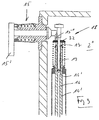
- FIG. 3 again shows the upper end of the shaft 14 'in an enlarged representation. and the span gas and Trinox valve 18 formed there with the valve needle 19.
- the valve needle 19 is provided in the upper end of the shaft 14 ' Disc 32 floating freely, i.e. slidable in the direction of the vertical axis VA intended.
- the disc 32 is used in a known manner in cooperation with the Control element 15 or its control curve 15 ′′ for closing the liquid valve 13.
- the valve needle 19 can thus be depressurized inside the bottle 4 attached to the filling element 3, whereby the lower end of the valve needle 19 the valve seat formed in the gas channel 16 16 'releases and thereby opens the span gas and Trinox valve 18.
- the here at Opening necessary pressure or pressure threshold result from the Mass weight of the valve needle 19. This opening pressure can also by a spring, not shown, can be increased or adjusted if necessary.
- the special feature is the double function of the valve needle 19 both as Tension gas as well as Tronix valve needle.
- the span gas and Trinox valve 18 results in Connection to the nozzle 27 provided in the channel 21 also regulates the Trinox pressure in the bottle neck of the bottle 4 attached to the filling element 3, in particular also in the form that pressure fluctuations in the Trinox channel 26 hardly occur affect the Trinox pressure in the bottle neck, i.e. the pressure in the bottle 4 is after opening the Trinox channel essentially as described above depending on the closing force or the pressure threshold of the clamping gas and Trinox valve 18 and the dimensioning of the nozzle 27 or from the latter Nozzle flowing into the bottle neck.
- the nozzle 27 and the closing force of the span gas or Trinox valve 18, i.e. the weight of the closing needle 19 are so set that the Trinox pressure formed in the bottle is just sufficient to Push excess product gently back into the interior 2.
- the pressure of the Pre-relief in the vacuum channel 22 can be set so low that a subsequent residual relief is no longer necessary.
Landscapes
- Chemical & Material Sciences (AREA)
- Chemical Kinetics & Catalysis (AREA)
- Filling Of Jars Or Cans And Processes For Cleaning And Sealing Jars (AREA)
- Filling Or Discharging Of Gas Storage Vessels (AREA)
- Basic Packing Technique (AREA)
Applications Claiming Priority (2)
| Application Number | Priority Date | Filing Date | Title |
|---|---|---|---|
| DE19818761A DE19818761A1 (de) | 1998-04-27 | 1998-04-27 | Einkammer-Füllsystem |
| DE19818761 | 1998-04-27 |
Publications (3)
| Publication Number | Publication Date |
|---|---|
| EP0953542A2 true EP0953542A2 (fr) | 1999-11-03 |
| EP0953542A3 EP0953542A3 (fr) | 2000-02-09 |
| EP0953542B1 EP0953542B1 (fr) | 2003-12-17 |
Family
ID=7865920
Family Applications (1)
| Application Number | Title | Priority Date | Filing Date |
|---|---|---|---|
| EP99105206A Expired - Lifetime EP0953542B1 (fr) | 1998-04-27 | 1999-03-12 | Vanne de remplissage pour une machine de remplissage |
Country Status (5)
| Country | Link |
|---|---|
| US (1) | US6213169B1 (fr) |
| EP (1) | EP0953542B1 (fr) |
| AT (1) | ATE256633T1 (fr) |
| BR (1) | BR9902482A (fr) |
| DE (2) | DE19818761A1 (fr) |
Cited By (2)
| Publication number | Priority date | Publication date | Assignee | Title |
|---|---|---|---|---|
| WO2015004001A1 (fr) * | 2013-07-09 | 2015-01-15 | Khs Gmbh | Système de remplissage ainsi que procédé de traitement de récipients au moyen d'un gaz de processus |
| US9969603B2 (en) | 2013-07-09 | 2018-05-15 | Khs Gmbh | Filling system |
Families Citing this family (24)
| Publication number | Priority date | Publication date | Assignee | Title |
|---|---|---|---|---|
| JP4701542B2 (ja) * | 2001-05-31 | 2011-06-15 | 澁谷工業株式会社 | 充填装置とその充填方法 |
| DE10259602A1 (de) * | 2002-12-19 | 2004-07-08 | Khs Maschinen- Und Anlagenbau Ag | Etikettiermaschine zum Etikettieren von Behältern |
| DE10359492B3 (de) * | 2003-12-13 | 2005-09-15 | Khs Maschinen- Und Anlagenbau Ag | Füllelement für eine Füllmaschine |
| DE10359312B4 (de) * | 2003-12-17 | 2016-02-25 | Khs Gmbh | Füllmaschine zum Füllen von Behältern |
| DE20319789U1 (de) * | 2003-12-20 | 2004-02-26 | Khs Maschinen- Und Anlagenbau Ag | Füllmaschine mit separatem Rückgaskanal |
| DE102004029788A1 (de) * | 2004-06-19 | 2006-01-12 | Khs Maschinen- Und Anlagenbau Ag | Vorrichtung zum Etikettieren von Gefäßen |
| US7523771B2 (en) | 2005-10-04 | 2009-04-28 | Adcor Industries, Inc. | Filling valve apparatus for a beverage filling machine |
| ITVI20050310A1 (it) * | 2005-11-24 | 2007-05-25 | Gruppo Bertolaso Spa | Apparecchiatura perfezionata per il riempimento di contenitori |
| DE102006017706A1 (de) | 2006-04-15 | 2007-10-25 | Khs Ag | Füllelemente sowie Füllmaschine mit einem Füllelement |
| ITVI20070100A1 (it) * | 2007-04-03 | 2008-10-04 | Gruppo Bertolaso Spa | Apparecchiatura perfezionata per il riempimento di contenitori |
| DE102007057285A1 (de) * | 2007-11-28 | 2009-06-04 | Krones Ag | Verfahren zum Befüllen von Behältern |
| DE102008030948A1 (de) * | 2008-07-02 | 2010-01-21 | Khs Ag | Füllsystem zum Füllen von Flaschen oder dergleichen Behältern sowie Füllmaschine |
| DE102010047883A1 (de) * | 2010-10-11 | 2012-04-12 | Khs Gmbh | Verfahren sowie Füllsystem zum volumen- und/oder mengengesteuerten Füllen von Behältern |
| ITBS20110036A1 (it) * | 2011-03-31 | 2012-10-01 | Corfill Internat S R L | Valvola di riempimento per uso alimentare con sistema di regolazione del livello di riempimento e relativo metodo di riempimento |
| KR101569603B1 (ko) * | 2011-04-06 | 2015-11-16 | 미쯔비시 쥬우꼬오 쇼구힌호오소오기까이 가부시키가이샤 | 회전식 충전기 및 회전식 충전기의 충전량 연산 방법 |
| CN102522223B (zh) * | 2011-11-09 | 2013-10-30 | 南京大学 | 真空灌装的可控灌装方法 |
| ITPD20120028A1 (it) * | 2012-02-07 | 2013-08-08 | Mbf Spa | Macchina riempitrice di contenitori con liquidi, e procedimento di riempimento di contenitori, in particolare mediante detta macchina riempitrice |
| ITTO20120117A1 (it) * | 2012-02-10 | 2013-08-11 | Agricola A Responsabilita Limitata Siglabile C S | Procedimento di vinificazione di vini dolci senza uso di conservanti |
| DE102013102616A1 (de) * | 2013-03-14 | 2014-09-18 | Khs Gmbh | Verfahren sowie Füllsystem zum Füllen von Behältern |
| DE102013106756A1 (de) * | 2013-06-27 | 2014-12-31 | Khs Gmbh | Verfahren sowie Füllsystem zum Füllen von Behältern |
| DE102013108638A1 (de) * | 2013-08-09 | 2015-03-05 | Khs Gmbh | Verfahren sowie System zum Spülen von Behältern |
| IT201600122730A1 (it) * | 2016-12-02 | 2018-06-02 | Co Mac Srl | Macchina modulare per il riempimento di bottiglie e lattine |
| DE102018127592B4 (de) * | 2018-11-06 | 2020-07-16 | Khs Gmbh | Füllelement, Füllsystem und Verfahren zum Füllen von Behältern |
| CN110272006B (zh) * | 2019-06-13 | 2024-03-08 | 江苏可奥熙光学材料科技有限公司 | 一种光学树脂单体用在线灌装装置 |
Family Cites Families (5)
| Publication number | Priority date | Publication date | Assignee | Title |
|---|---|---|---|---|
| DE3008386C2 (de) * | 1980-03-05 | 1986-01-16 | Seitz Enzinger Noll Maschinenbau Ag, 6800 Mannheim | Füllelement für Gegendruck-Füllmaschinen |
| DE3825093C2 (de) * | 1988-07-23 | 1994-01-13 | Kronseder Maschf Krones | Verfahren und Vorrichtung zum Füllen von Flaschen oder dgl. in Gegendruckfüllmaschinen |
| DE4213737A1 (de) * | 1991-10-17 | 1993-04-22 | Seitz Enzinger Noll Masch | Verfahren zum fuellen von flaschen oder dergleichen behaelter mit einem fluessigen fuellgut sowie vorrichtung zum durchfuehren dieses verfahrens |
| DE9321223U1 (de) * | 1992-08-08 | 1996-09-12 | Mette, Manfred, Dr.-Ing., 22145 Hamburg | Gegendruck-Fülleinrichtung zum Abfüllen von CO¶2¶-haltigen Getränken in Flaschen oder andere Behälter |
| DE4241545A1 (de) * | 1992-12-10 | 1994-06-16 | Khs Masch & Anlagenbau Ag | Füllmaschine, insbesondere Gegendruck-Füllmaschine |
-
1998
- 1998-04-27 DE DE19818761A patent/DE19818761A1/de not_active Withdrawn
-
1999
- 1999-03-12 DE DE59908059T patent/DE59908059D1/de not_active Expired - Lifetime
- 1999-03-12 AT AT99105206T patent/ATE256633T1/de active
- 1999-03-12 EP EP99105206A patent/EP0953542B1/fr not_active Expired - Lifetime
- 1999-04-22 BR BR9902482A patent/BR9902482A/pt not_active IP Right Cessation
- 1999-04-26 US US09/299,497 patent/US6213169B1/en not_active Expired - Lifetime
Cited By (3)
| Publication number | Priority date | Publication date | Assignee | Title |
|---|---|---|---|---|
| WO2015004001A1 (fr) * | 2013-07-09 | 2015-01-15 | Khs Gmbh | Système de remplissage ainsi que procédé de traitement de récipients au moyen d'un gaz de processus |
| US9809436B2 (en) | 2013-07-09 | 2017-11-07 | Khs Gmbh | Filling system and method for the treatment of containers with a process gas |
| US9969603B2 (en) | 2013-07-09 | 2018-05-15 | Khs Gmbh | Filling system |
Also Published As
| Publication number | Publication date |
|---|---|
| BR9902482A (pt) | 2000-03-21 |
| ATE256633T1 (de) | 2004-01-15 |
| DE19818761A1 (de) | 1999-10-28 |
| DE59908059D1 (de) | 2004-01-29 |
| EP0953542A3 (fr) | 2000-02-09 |
| US6213169B1 (en) | 2001-04-10 |
| EP0953542B1 (fr) | 2003-12-17 |
Similar Documents
| Publication | Publication Date | Title |
|---|---|---|
| EP0953542B1 (fr) | Vanne de remplissage pour une machine de remplissage | |
| EP1584601B1 (fr) | Machine de remplissage du type à carrousel | |
| EP1692071B1 (fr) | Element de remplissage pour machine de remplissage et machine de remplissage equipee d'elements de remplissage de ce type | |
| EP1204555B1 (fr) | Dispositif de conservation d'une bouteille pour boissons ouverte | |
| EP2307306B1 (fr) | Système de remplissage pour remplir des bouteilles ou récipients similaires et machine de remplissage correspondante | |
| DE3431107C2 (de) | Verfahren und Vorrichtung zum Füllen von Flaschen o.dgl. | |
| EP2996980B1 (fr) | Système et machine de remplissage de récipients | |
| DE3446501C2 (fr) | ||
| EP2768762B1 (fr) | Procédé et machine de remplissage de bouteilles avec un produit à conditionner liquide | |
| EP0588356B1 (fr) | Dispositif de remplissage de bouteilles ou de récipients similaires | |
| DE102013103639A1 (de) | Füllelement, Füllsystem sowie Verfahren zum Füllen von Behältern | |
| DE4402980C1 (de) | Füllsystem zum Abfüllen eines flüssigen Füllgutes in Flaschen, Dosen oder dgl. Behälter | |
| DE102005003222A1 (de) | Vorrichtung zum Füllen von Gefäßen | |
| DE20110362U1 (de) | Füllrohrloses Füllelement für eine Füllmaschine zum sauerstoffarmen Abfüllen eines Getränks | |
| DE2454888A1 (de) | Flaschenfuellmaschine | |
| DE4342142C2 (de) | Vorrichtung zum Füllen von Flaschen oder dergl. Behälter mit einem flüssigen Füllgut | |
| DE102016105552A1 (de) | Füllventil zum Befüllen eines Behälters mit einem Füllprodukt | |
| EP0554690A1 (fr) | Procédé de remplissage des bouteilles ou de récipients similaires avec un produit liquide et dispositif pour la mise en oeuvre du procédé | |
| DE2123865A1 (de) | Füllelement | |
| DE29807610U1 (de) | Einkammer-Füllsystem | |
| DE2638749C3 (de) | Vorrichtung zum Füllen von Flaschen bei gleichbleibendem Druck | |
| DE102020110899A1 (de) | Verfahren zum Befüllen von Behältern | |
| EP0416473B1 (fr) | Tête de remplissage pour embouteilleuse à contre-pression | |
| EP4566982A1 (fr) | Organe de remplissage avec dispositif à vide | |
| DD264414A1 (de) | Vorrichtung zur steuerung von fuellventilen |
Legal Events
| Date | Code | Title | Description |
|---|---|---|---|
| PUAI | Public reference made under article 153(3) epc to a published international application that has entered the european phase |
Free format text: ORIGINAL CODE: 0009012 |
|
| AK | Designated contracting states |
Kind code of ref document: A2 Designated state(s): AT BE DE FR IT NL |
|
| AX | Request for extension of the european patent |
Free format text: AL;LT;LV;MK;RO;SI |
|
| RTI1 | Title (correction) |
Free format text: FILLING VALVE FOR A FILLING MACHINE |
|
| PUAL | Search report despatched |
Free format text: ORIGINAL CODE: 0009013 |
|
| RIN1 | Information on inventor provided before grant (corrected) |
Inventor name: KRULITSCH, DIETER-RUDOLF Inventor name: CLUESSERATH, LUDWIG |
|
| AK | Designated contracting states |
Kind code of ref document: A3 Designated state(s): AT BE CH CY DE DK ES FI FR GB GR IE IT LI LU MC NL PT SE |
|
| AX | Request for extension of the european patent |
Free format text: AL;LT;LV;MK;RO;SI |
|
| 17P | Request for examination filed |
Effective date: 20000308 |
|
| AKX | Designation fees paid |
Free format text: AT BE DE FR IT NL |
|
| 17Q | First examination report despatched |
Effective date: 20030310 |
|
| GRAH | Despatch of communication of intention to grant a patent |
Free format text: ORIGINAL CODE: EPIDOS IGRA |
|
| GRAS | Grant fee paid |
Free format text: ORIGINAL CODE: EPIDOSNIGR3 |
|
| GRAA | (expected) grant |
Free format text: ORIGINAL CODE: 0009210 |
|
| AK | Designated contracting states |
Kind code of ref document: B1 Designated state(s): AT BE DE FR IT NL |
|
| REF | Corresponds to: |
Ref document number: 59908059 Country of ref document: DE Date of ref document: 20040129 Kind code of ref document: P |
|
| ET | Fr: translation filed | ||
| PLBE | No opposition filed within time limit |
Free format text: ORIGINAL CODE: 0009261 |
|
| STAA | Information on the status of an ep patent application or granted ep patent |
Free format text: STATUS: NO OPPOSITION FILED WITHIN TIME LIMIT |
|
| 26N | No opposition filed |
Effective date: 20040920 |
|
| REG | Reference to a national code |
Ref country code: NL Ref legal event code: TD Effective date: 20111114 |
|
| REG | Reference to a national code |
Ref country code: FR Ref legal event code: CD Owner name: KHS GMBH Effective date: 20111122 Ref country code: FR Ref legal event code: CD Owner name: KHS GMBH Effective date: 20111121 |
|
| REG | Reference to a national code |
Ref country code: AT Ref legal event code: PC Ref document number: 256633 Country of ref document: AT Kind code of ref document: T Owner name: KHS GMBH, DE Effective date: 20111220 |
|
| BECN | Be: change of holder's name |
Owner name: KHS G.M.B.H. Effective date: 20120314 |
|
| REG | Reference to a national code |
Ref country code: FR Ref legal event code: PLFP Year of fee payment: 18 |
|
| PGFP | Annual fee paid to national office [announced via postgrant information from national office to epo] |
Ref country code: NL Payment date: 20160321 Year of fee payment: 18 |
|
| PGFP | Annual fee paid to national office [announced via postgrant information from national office to epo] |
Ref country code: BE Payment date: 20160321 Year of fee payment: 18 Ref country code: AT Payment date: 20160322 Year of fee payment: 18 Ref country code: FR Payment date: 20160321 Year of fee payment: 18 |
|
| PGFP | Annual fee paid to national office [announced via postgrant information from national office to epo] |
Ref country code: DE Payment date: 20160330 Year of fee payment: 18 |
|
| PGFP | Annual fee paid to national office [announced via postgrant information from national office to epo] |
Ref country code: IT Payment date: 20160324 Year of fee payment: 18 |
|
| REG | Reference to a national code |
Ref country code: DE Ref legal event code: R119 Ref document number: 59908059 Country of ref document: DE |
|
| REG | Reference to a national code |
Ref country code: NL Ref legal event code: MM Effective date: 20170401 |
|
| REG | Reference to a national code |
Ref country code: AT Ref legal event code: MM01 Ref document number: 256633 Country of ref document: AT Kind code of ref document: T Effective date: 20170312 |
|
| REG | Reference to a national code |
Ref country code: FR Ref legal event code: ST Effective date: 20171130 |
|
| PG25 | Lapsed in a contracting state [announced via postgrant information from national office to epo] |
Ref country code: AT Free format text: LAPSE BECAUSE OF NON-PAYMENT OF DUE FEES Effective date: 20170312 Ref country code: NL Free format text: LAPSE BECAUSE OF NON-PAYMENT OF DUE FEES Effective date: 20170401 Ref country code: FR Free format text: LAPSE BECAUSE OF NON-PAYMENT OF DUE FEES Effective date: 20170331 Ref country code: DE Free format text: LAPSE BECAUSE OF NON-PAYMENT OF DUE FEES Effective date: 20171003 |
|
| PG25 | Lapsed in a contracting state [announced via postgrant information from national office to epo] |
Ref country code: IT Free format text: LAPSE BECAUSE OF NON-PAYMENT OF DUE FEES Effective date: 20170312 |
|
| REG | Reference to a national code |
Ref country code: BE Ref legal event code: MM Effective date: 20170331 |
|
| PG25 | Lapsed in a contracting state [announced via postgrant information from national office to epo] |
Ref country code: BE Free format text: LAPSE BECAUSE OF NON-PAYMENT OF DUE FEES Effective date: 20170331 |