EP0953553A1 - Verfahren zur Herstellung eines Verbundkörpers - Google Patents
Verfahren zur Herstellung eines Verbundkörpers Download PDFInfo
- Publication number
- EP0953553A1 EP0953553A1 EP99303446A EP99303446A EP0953553A1 EP 0953553 A1 EP0953553 A1 EP 0953553A1 EP 99303446 A EP99303446 A EP 99303446A EP 99303446 A EP99303446 A EP 99303446A EP 0953553 A1 EP0953553 A1 EP 0953553A1
- Authority
- EP
- European Patent Office
- Prior art keywords
- aluminum
- substrate
- matrix
- infiltrating material
- substrates
- Prior art date
- Legal status (The legal status is an assumption and is not a legal conclusion. Google has not performed a legal analysis and makes no representation as to the accuracy of the status listed.)
- Withdrawn
Links
Images


Classifications
-
- C—CHEMISTRY; METALLURGY
- C04—CEMENTS; CONCRETE; ARTIFICIAL STONE; CERAMICS; REFRACTORIES
- C04B—LIME, MAGNESIA; SLAG; CEMENTS; COMPOSITIONS THEREOF, e.g. MORTARS, CONCRETE OR LIKE BUILDING MATERIALS; ARTIFICIAL STONE; CERAMICS; REFRACTORIES; TREATMENT OF NATURAL STONE
- C04B37/00—Joining burned ceramic articles with other burned ceramic articles or other articles by heating
- C04B37/02—Joining burned ceramic articles with other burned ceramic articles or other articles by heating with metallic articles
-
- B—PERFORMING OPERATIONS; TRANSPORTING
- B32—LAYERED PRODUCTS
- B32B—LAYERED PRODUCTS, i.e. PRODUCTS BUILT-UP OF STRATA OF FLAT OR NON-FLAT, e.g. CELLULAR OR HONEYCOMB, FORM
- B32B15/00—Layered products comprising a layer of metal
- B32B15/01—Layered products comprising a layer of metal all layers being exclusively metallic
-
- C—CHEMISTRY; METALLURGY
- C04—CEMENTS; CONCRETE; ARTIFICIAL STONE; CERAMICS; REFRACTORIES
- C04B—LIME, MAGNESIA; SLAG; CEMENTS; COMPOSITIONS THEREOF, e.g. MORTARS, CONCRETE OR LIKE BUILDING MATERIALS; ARTIFICIAL STONE; CERAMICS; REFRACTORIES; TREATMENT OF NATURAL STONE
- C04B41/00—After-treatment of mortars, concrete, artificial stone or ceramics; Treatment of natural stone
- C04B41/45—Coating or impregnating, e.g. injection in masonry, partial coating of green or fired ceramics, organic coating compositions for adhering together two concrete elements
- C04B41/50—Coating or impregnating, e.g. injection in masonry, partial coating of green or fired ceramics, organic coating compositions for adhering together two concrete elements with inorganic materials
- C04B41/51—Metallising, e.g. infiltration of sintered ceramic preforms with molten metal
- C04B41/515—Other specific metals
- C04B41/5155—Aluminium
-
- C—CHEMISTRY; METALLURGY
- C22—METALLURGY; FERROUS OR NON-FERROUS ALLOYS; TREATMENT OF ALLOYS OR NON-FERROUS METALS
- C22C—ALLOYS
- C22C1/00—Making non-ferrous alloys
- C22C1/10—Alloys containing non-metals
- C22C1/1036—Alloys containing non-metals starting from a melt
Definitions
- This invention relates to a method of manufacturing a joint body constructed of at least one pair of substrates comprising aluminum matrix composite which is made up of an aluminum or aluminum alloy matrix and a reinforcing ceramic.
- a method of producing ceramic matrix or metal matrix composite by a Lanxide process is known (for example, “Net Shape Manufacturing of CMC and MMC by Lanxide Processes” in “ceramics” 32 (1997) No. 2 p93-97).
- a method of producing ceramic matrix or metal matrix composite by a Lanxide process for example, “Net Shape Manufacturing of CMC and MMC by Lanxide Processes” in “ceramics” 32 (1997) No. 2 p93-97).
- the wettability between melted aluminum and ceramic is made to be high by the Lanxide process in each composite of silicon carbide/aluminum and alumina/aluminum systems is known, which method is in general named non-pressurized metal infiltration process.
- a preform having an almost final objective shape is formed by using silicon carbide or alumina as reinforcing material, a barrier film for growth stopping is applied on a surface except for surfaces which are put into contact with an aluminum alloy.
- This preform is usually put into contact with the aluminum alloy in nitrogen having about 800°C, aluminum infiltrates into pores of the preform while wetting the ceramic to form a composite.
- the resulting composite is confirmed to have an aluminum nitride layer at the boundary between the ceramic and aluminum.
- an object of the invention to provide a novel method of manufacturing a joint body constructed of at least one pair of substrates comprised of an aluminum matrix composite which is made of an aluminum or aluminum alloy matrix and a reinforcing ceramic.
- a method of manufacturing a joint body constructed of at least one pair of substrates comprised of an aluminum matrix composite which is made up of an aluminum or aluminum alloy matrix and a reinforcing ceramic in which each joint surface of each substrate is put into contact with each other, the infiltrating material made up of an aluminum alloy containing aluminum of not less than 70 mol% is put into contact with at least one of the substrates, and then the substrates and the infiltrating material are subjected to the heat treatment in a vacuum of a high level and at a temperature of melting the matrix and the infiltrating material to infiltrate the aluminum alloy constituting the infiltrating material into the substrate, and the melted aluminum or aluminum alloy is diffused across each joint surface of each substrate.
- the joint body made up of the aluminum matrix composite which has a trace of impurities or an undetectable amount of impurities at the joint boundary surface of each substrate can be obtained.
- the joint portion has a high heat resistance and joint strength, and does not have brittleness.
- one substrate lA and the other substrate 1B are prepared, and each joint surface la of each substrate is opposite to each other, and then a sheet or film shaped infiltrating material 2 is placed between the joint surfaces.
- the infiltrating material 2 is made up of aluminum alloy containing aluminum of not less than 70 mol%.
- the substrates 1A and 1B and the infiltrating material 2 are subjected to a heat treatment in a vacuum of a high level at a temperature of melting the matrix and the infiltrating material to simultaneously melt them.
- the infiltrating material is diffused as shown by an arrow B and blends with the matrix.
- a pressure of not less than 20 gf/cm 2 is preferably applied thereto in the direction perpendicular to each joint surface la of each substrate as shown by an arrow A.
- An upper limit of the pressure is a pressure of not destroying each substrate, and practically not more than 100 kgf/cm 2 .
- the infiltrating material 2 preferably has a thickness of 5-500 ⁇ m.
- a partially infiltrated region where the matrix is partially infiltrated and pores remain is preferably formed at the joint surface la side of at least one of the substrates 1A and 1B, the infiltrating material being infiltrated into the pores in the partially infiltrated region during the heat treatment.
- the substrates 1A and 1B are respectively provided with the partially infiltrated regions 11B at the joint surface sides.
- a region 11c where aluminum is infiltrated is respectively formed in an outer side of each partially infiltrated region 11b of each substrate.
- the region 11c is a usual aluminum matrix composite, and the pores in the composite is charged with the matrix and almost none of the pores remain.
- the region 11c preferably has a relative density of not less than 90%.
- the matrix is formed in pores in the partially infiltrated region 11b of the composite, but the matrix is short to charge the whole pores therewith.
- the region 11b preferably has a relative density of 50-80%.
- the infiltrating material 2 diffuses into each partially infiltrated region 11b as shown by an arrow B to infiltrate. Formation of the partially infiltrated region facilitates to infiltrate the infiltrating material into each substrate and improves the joint strength of the substrate.
- the infiltrating material infiltrated into the partially infiltrated region functions as the matrix. After joining each substrate, there is a case of remaining of the infiltrating material at the joint surface of each substrate. But the infiltration can be continued till the infiltrating material disappears from the joint boundary surface.
- each joint surface la of each substrate 1A or 1B is put into contact with each other, and the infiltrating material 12 made up of an aluminum alloy containing aluminum of not less than 70 mol% is put into contact with, for example, one substrate 1A.
- the substrates 1A and 1B and the infiltrating material 12 are subjected to the heat treatment in a vacuum of a high level and at a temperature of melting the matrix and the infiltrating material 12 to infiltrate the aluminum alloy constituting the infiltrating material 12 into the substrate 1A as shown by an arrow C, and subsequently the melted aluminum or aluminum alloy is diffused across each joint surface la of each substrate 1A or 1B as shown by an arrow D.
- one body of joint body can be obtained, and a tertiary phase can not be detected at the joint boundary surface.
- At least one of the substrates 11A and 11B is provided with the partially infiltrated region where the matrix is partially infiltrated and pores remain.
- the aluminum or aluminum alloy is infiltrated into the pores in the partially infiltrated region 11b, and diffused from at least one of the substrates, as shown by an arrow D, across each joint surface 11a of each substrate.
- At least one of the substrates is wholly made up of a partially infiltrated aluminum matrix composite.
- the infiltrating material preferably has a melting point lower than the matrix in the aluminum matrix composite.
- the infiltrating material preferably melts earlier than the matrix, particularly a difference between the melting points is preferable to be not less than 15°C. This improves a good shape retention in the whole joint body.
- An atmosphere during the heat treatment is required to be in a vacuum of a high level in which oxidation or nitration in the joint surface and the surface of the substrate can be effectively prevented.
- a pressure during the heat treatment is preferably not more than 1 ⁇ 10 -3 Torr, and more preferably 1 ⁇ 10 -4 Torr. From the viewpoint of preventing evaporation of a metal ingredient during the heat treatment, it is preferable to be not less than 1 ⁇ 10 -7 Torr.
- the joint body according to the invention can be suitably used as a member in a semiconductor manufacturing apparatus or a liquid crystal display manufacturing apparatus, for example, as a high temperature resistant member in a reaction chamber or a large scale heater embedded with a heat generator.
- a susceptor embedded with a heat generator an electrode for electrostatic chuck, or an electrode for generating a high frequency
- an apparatus provided with a shaft or a backboard which is joined to the susceptor may be exemplified.
- An apparatus such as a shadow ring, a tube, a dome, a shower plate or the like may also be exemplified.
- a material for the ceramic constituting the preform is not limited when the aluminum or aluminum alloy can infiltrate thereinto. But, aluminum based ceramic is preferable, and alumina or aluminum nitride is particularly preferable.
- a predetermined ceramic particles are diffused in a solvent such as isopropanol or the like, and mixed with an organic binder such as a liquid acrylic copolymer binder or the like, and then they are stirred and mixed in a large scale pot mill for 2-40 hours to obtain a slurry. And then, particles having a size of 30-100 ⁇ m are granulated from the slurry by using an explosion proof spray dry machine. Next, the granulated particles are placed into a predetermined mole, and press molded under 200-7000 kgf/cm 2 by using an oilhydraulic press machine to manufacture the preform.
- a solvent such as isopropanol or the like
- an organic binder such as a liquid acrylic copolymer binder or the like
- the ceramic particles are mixed with ethanol or the like by spraying to obtain a powder, instead of manufacturing the slurry with the organic binder, and then the powder is press molded in the same manner as the above one to obtain the preform.
- a spontaneous infiltration process for example, a pressure infiltration process, or a vacuum infiltration process may be used.
- at least one active metal selected from a group consisting of magnesium, titanium, zirconium, and hafnium is added into the aluminum alloy, the aluminum alloy matrix is infiltrated into the preform by using a non-pressurized metal infiltration process, to produce aluminum nitride at the boundary surface between the matrix and the ceramic constituting the preform. This brings a good wettability between the ceramic and the matrix.
- infiltration of aluminum is preferably stopped before completion of the infiltration.
- aluminum is infiltrated into the whole preform to obtain the aluminum matrix composite, and then the composite is treated by acid to selectively dissolve the matrix. As the result, the partially infiltrated region is obtained.
- the substrate wholly made up of the partially infiltrated aluminum matrix composite can be produced in the same manner.
- infiltrating aluminum alloys which may be used as the substrate matrix and as the infiltrating material are described below.
- the infiltrating material is preferably made up of the aluminum alloy containing aluminum of 70 mol%. When it is less than 70 mol%, a metal other then the aluminum become an alloy or an intermetllic compound with aluminum or aluminum alloy in the matrix. This may brings brittleness.
- the alloy contains 1-10 mol% of at least one active metal selected from a group consisting of magnesium, titanium, zirconium, and hafnium, more preferably, magnesium.
- the active metal of not less than 1 mol% improves an affinity to a metal ingredient in the substrate or the reinforcing material, and facilitated to infiltrate.
- the active metal of not more than 10 mol% suppresses to locally generate the intermetallic compound or the like causing brittleness.
- the aluminum content in the alloy is obtained as remainder, by subtracting a total content of the active metal content and the tertiary ingredient content mentioned below from 100 mol%, when the infiltrating material total content or the total content of the aluminum alloy constituting the infiltrating material is assumed to be 100 mol%.
- the tertiary ingredient can be contained in the infiltrating material or the aluminum alloy constituting the infiltrating material.
- silicon or boron is preferable because it does not influence aluminum.
- Such a tertiary ingredient lowers the melting point. That is, the infiltrating material added with the tertiary ingredient has a flowability higher than that not added therewith in comparing at the same temperature.
- the tertiary ingredient content is preferable to be 1.5-10 mol%.
- the infiltrating material or the alloy constituting the infiltrating material preferably contains magnesium of 1-6 mol% and silicon of 1.5-10 mol%.
- a film made up of at least one metal selected from a group consisting of magnesium, titanium, zirconium, and hafnium may be formed between the joint surface of the substrate and the infiltrating material or between the joint surfaces of the substrates by sputtering, deposition, friction welding, plating or the like.
- a foil made up of at least one metal selected from a group consisting of magnesium, titanium, zirconium, and hafnium may also be placed between the joint surface of the substrate and the infiltrating material or between the joint surfaces of the substrates.
- At least one of an oxide film and a nitride film on the joint surface is preferably removed by washing each joint surface of each substrate by using an acid solution or an alkaline solution.
- an oxide film or a nitride film remains on the joint surface, there is a fear that it prevents the infiltrating material or the matrix from infiltrating into the substrate across the joint surface.
- Aluminum nitride particles having an average size of 16 ⁇ m is dispersed in an isopropanol solvent, and then a liquid acrylic copolymer binder is added thereto and stirred and mixed by a large scale pot mill for 4 hours to obtain a slurry.
- a sphere shaped powder having a size of about 150 ⁇ m is granulated from the slurry by an explosion proof spray dry machine. The granulated powder is charged into a predetermined mold and uniaxially press molded under a pressure of 200 kgf/cm 2 by an oilhydraulic press to obtain a large preform having a diameter of 380 mm and a thickness of 30 mm.
- the preform After sufficiently drying and degreasing the preform, it is put into contact with a melted aluminum alloy liquid (aluminum of 92.6 mol%, magnesium of 5.5 mol%, silicon of 1.9 mol%), in an atmosphere consisting of nitrogen of 99 % and hydrogen of 1 %, under 1.5 atmospheric pressure, at a temperature of 900°C, for 24 hours, and is infiltrated with aluminum by non-pressurized metal infiltration process, and then the preform is pulled up from the melted liquid to obtain an aluminum matrix composite.
- a melted aluminum alloy liquid aluminum of 92.6 mol%, magnesium of 5.5 mol%, silicon of 1.9 mol%
- substrates 1C and 1D having dimensions of 20 mm ⁇ 20 mm ⁇ 20 mm are cut out from the composite, each joint surface of each substrate is ground by a whetstone of #800. Next, each joint surface is washed by acetone and isopropyl alcohol, and further washed by 30 % of ammonia water at 70°C for 10 minutes. And a nickel plating is applied to each joint surface.
- An aluminum alloy sheet 2A (an infiltrating material) (silicon of 8.7 mol%, magnesium of 1.1 mol%) rolled to dimensions of 20 mm ⁇ 20 mm ⁇ 0.1 mm, as shown in Fig. 3, is inserted between the joint surfaces of the substrates.
- a carbon block 5 of 20 mm ⁇ 20 mm ⁇ 10 mm is placed on the upper substrate 1C, and further a molybdenum block 6 of 20 mm ⁇ 20 mm ⁇ 50 mm is placed on the carbon block to obtain a laminated body.
- the laminated body is heated up to 700°C in a vacuum of not less than 3 ⁇ 10 -5 Torr and held at 700°C for 10 minutes, and cooled in a furnace to obtain a joint body.
- a joint body is manufactured in the same manner as Example 1 except that before the heat treatment, titanium foils of 20 mm ⁇ 20 mm ⁇ 0.005 mm are respectively inserted between each joint surface and an infiltrating material, without forming the nickel plating on each joint surface of each substrate.
- a joint body is manufactured in the same manner as Example 1 except that each joint surface of each substrate is washed for 1 minute by 1 % of a hydrochloric acid solution at 20°C, instead of washing by the ammonia water.
- An aluminum matrix composite is manufactured in the same manner as Example 1. And a plate shaped substrate having dimensions of 60 mm ⁇ 60 mm ⁇ 20 mm and a cylindrical substrate having an outer diameter of 50 mm, an inner diameter of 40 mm and a length of 30 mm are cut out from the composite. Each joint surface of the plate shaped substrate and the cylindrical substrate are ground by a whetstone of #800. Next, each joint surface is washed by acetone and isopropyl alcohol, and further washed by 30 % of ammonia water at 70°C for 10 minutes.
- An aluminum alloy sheet (silicon of 8.7 mol%, magnesium of 1.1 mol%) rolled to dimensions of 20 mm ⁇ 20 mm ⁇ 0.1 mm is inserted between the plate shaped substrate and the cylindrical substrate, and further, titanium foils having a thickness of 10 ⁇ m are respectively inserted between the plate shaped substrate and the sheet and between the cylindrical substrate and the sheet.
- a carbon block of 70 mm ⁇ 70 mm ⁇ 10 mm is placed on the upper cylindrical substrate, and further a molybdenum block of 30 mm ⁇ 30 mm ⁇ 50 mm is placed on the carbon block to obtain a laminated body.
- the laminated body is heated up to 700°C in a vacuum of not less than 3 ⁇ 10 -5 Torr and held at 700°C for 10 minutes, and cooled in a furnace to obtain a joint body.
- a joint test is conducted.
- Aluminum nitride particles having an average size of 23 ⁇ m is dispersed in an isopropanol solvent, and then a liquid acrylic copolymer binder is added thereto and stirred and mixed by a large scale pot mill for 4 hours to obtain a slurry.
- a sphere shaped powder having a size of about 150 ⁇ m is granulated from the slurry by an explosion proof spray dry machine. The granulated powder is charged into a predetermined mold and uniaxially press molded under a pressure of 200 kgf/cm 2 by oilhydraulic press to obtain a large preform having a diameter of 380 mm and a thickness of 30 mm.
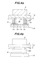
- a substrate 11D for a susceptor and a substrate 11C for a shaft are cut out by grinding, and degreased.
- the preform for the substrate 11D is of 60 mm ⁇ 60 mm ⁇ 10 mm
- a cylindrical portion 7 of the preform for the substrate 11C for the shaft is of an outer diameter of 36 mm, an inner diameter of 30 mm, and a length of 15 mm
- a cylindrical flange portion 8 is of an outer diameter of 50 mm, an inner diameter of 30 mm, and a thickness of 5 mm.
- a packing density of each preform is 57 % of a theoretical density (porosity: 43 %)
- each preform is placed with an aluminum alloy lump (silicon of 2.9 mol%, magnesium of 5.5 mol%) on an upper surface thereof, and heated up to 900°C at rate of 300°C/hour, under an atmospheric pressure while nitrogen of 96 % and hydrogen of 4 % are flowed, and held at 900°C.
- the aluminum alloy is infiltrated into each preform to obtain substrates 11C and 11D.
- 11c shows a completely infiltrated region and 11b shows a partially infiltrated region.
- An amount of the infiltrating material infiltrated is controlled by the alloy amount and a retention time at 900°C.
- each joint surface 1 la is ground by a whetstone of #800 and made to plane, and then is washed by acetone and isopropyl alcohol, and further washed by 30 % of ammonia water at 70°C for 10 minutes.
- An infiltrating material 12A made up of a ring shaped alloy lump (silicon of 7.7 mol%, magnesium of 2.8 mol%) is placed on the flange portion 8 of the substrate 11C.
- the laminated body in Fig. 4 is placed in an electric furnace, and heated up to 900°C at rate of 150°C/hour, under an atmospheric pressure while nitrogen of 96 % and hydrogen of 4 % are flowed, and held at 900°C for 22 hours. Thereby, the aluminum alloy is infiltrated into the vicinity of the joint portion.
- a carbon block 5 of 70 mm ⁇ 70 mm ⁇ 10 mm and a molybdenum block 6 of 30 mm ⁇ 30 mm ⁇ 50 % are placed thereon.
Landscapes
- Chemical & Material Sciences (AREA)
- Engineering & Computer Science (AREA)
- Materials Engineering (AREA)
- Organic Chemistry (AREA)
- Ceramic Engineering (AREA)
- Mechanical Engineering (AREA)
- Metallurgy (AREA)
- Structural Engineering (AREA)
- Inorganic Chemistry (AREA)
- Ceramic Products (AREA)
- Manufacture Of Alloys Or Alloy Compounds (AREA)
- Pressure Welding/Diffusion-Bonding (AREA)
Applications Claiming Priority (2)
| Application Number | Priority Date | Filing Date | Title |
|---|---|---|---|
| JP12229098A JP3987201B2 (ja) | 1998-05-01 | 1998-05-01 | 接合体の製造方法 |
| JP12229098 | 1998-05-01 |
Publications (1)
| Publication Number | Publication Date |
|---|---|
| EP0953553A1 true EP0953553A1 (de) | 1999-11-03 |
Family
ID=14832305
Family Applications (1)
| Application Number | Title | Priority Date | Filing Date |
|---|---|---|---|
| EP99303446A Withdrawn EP0953553A1 (de) | 1998-05-01 | 1999-04-30 | Verfahren zur Herstellung eines Verbundkörpers |
Country Status (5)
| Country | Link |
|---|---|
| US (1) | US6328198B1 (de) |
| EP (1) | EP0953553A1 (de) |
| JP (1) | JP3987201B2 (de) |
| KR (1) | KR100322785B1 (de) |
| TW (1) | TW387870B (de) |
Cited By (2)
| Publication number | Priority date | Publication date | Assignee | Title |
|---|---|---|---|---|
| CN107117986A (zh) * | 2010-05-21 | 2017-09-01 | 阔斯泰公司 | 陶瓷对陶瓷接合件及相关方法 |
| CN109473037A (zh) * | 2018-10-31 | 2019-03-15 | 青岛海信电器股份有限公司 | 一种一体化整机背板和显示装置 |
Families Citing this family (14)
| Publication number | Priority date | Publication date | Assignee | Title |
|---|---|---|---|---|
| AT408345B (de) * | 1999-11-17 | 2001-10-25 | Electrovac | Verfahren zur festlegung eines aus metall-matrix- composite-(mmc-) materiales gebildeten körpers auf einem keramischen körper |
| US6378755B1 (en) * | 2000-11-08 | 2002-04-30 | General Electric Company | Joined structure utilizing a ceramic foam bonding element, and its fabrication |
| US6749518B2 (en) * | 2002-04-08 | 2004-06-15 | General Electric Company | Inertia welded shaft and method therefor |
| US7532481B2 (en) * | 2004-04-05 | 2009-05-12 | Mitsubishi Materials Corporation | Al/AlN joint material, base plate for power module, power module, and manufacturing method of Al/AlN joint material |
| US7621435B2 (en) * | 2004-06-17 | 2009-11-24 | The Regents Of The University Of California | Designs and fabrication of structural armor |
| US7857194B2 (en) * | 2007-05-01 | 2010-12-28 | University Of Dayton | Method of joining metals to ceramic matrix composites |
| JP5009095B2 (ja) * | 2007-08-29 | 2012-08-22 | 太平洋セメント株式会社 | 接合体及びその製造方法 |
| US8727203B2 (en) | 2010-09-16 | 2014-05-20 | Howmedica Osteonics Corp. | Methods for manufacturing porous orthopaedic implants |
| TWI457470B (zh) * | 2010-12-31 | 2014-10-21 | Hon Hai Prec Ind Co Ltd | 掛具 |
| US8684256B2 (en) | 2011-11-30 | 2014-04-01 | Component Re-Engineering Company, Inc. | Method for hermetically joining plate and shaft devices including ceramic materials used in semiconductor processing |
| US9624137B2 (en) * | 2011-11-30 | 2017-04-18 | Component Re-Engineering Company, Inc. | Low temperature method for hermetically joining non-diffusing ceramic materials |
| US8932690B2 (en) | 2011-11-30 | 2015-01-13 | Component Re-Engineering Company, Inc. | Plate and shaft device |
| US9999947B2 (en) | 2015-05-01 | 2018-06-19 | Component Re-Engineering Company, Inc. | Method for repairing heaters and chucks used in semiconductor processing |
| CN114007798B (zh) * | 2019-06-17 | 2023-03-24 | 株式会社神户制钢所 | 铝材的接合方法 |
Citations (9)
| Publication number | Priority date | Publication date | Assignee | Title |
|---|---|---|---|---|
| EP0164830A2 (de) * | 1984-06-13 | 1985-12-18 | Corning Glass Works | Reaktionsgebundene Carbid-, Nitrid-, Borid-, Silicid- oder Sulfid-Formkörper |
| EP0238758A2 (de) * | 1986-03-28 | 1987-09-30 | Martin Marietta Corporation | Schweissen unter Gebrauch von Metall-Keramik-Zusammensetzungen |
| US4752537A (en) * | 1985-06-10 | 1988-06-21 | The Boeing Company | Metal matrix composite fiber reinforced weld |
| US4923832A (en) * | 1986-05-08 | 1990-05-08 | Lanxide Technology Company, Lp | Method of making shaped ceramic composites with the use of a barrier |
| EP0378501A1 (de) * | 1989-01-13 | 1990-07-18 | Lanxide Technology Company, Lp. | Verfahren zum Verbinden eines keramischen Verbundwerkstoffkörpers mit einem zweiten Körper und so hergestellte Gegenstände |
| EP0409764A2 (de) * | 1989-07-21 | 1991-01-23 | Lanxide Technology Company, Lp | Verfahren zur Herstellung von Macro-Verbundkörpern mittels selbsterzeugter Vakuumtechnik und danach hergestellte Produkte |
| WO1992000937A2 (en) * | 1990-07-12 | 1992-01-23 | Lanxide Technology Company, Lp | Joining methods for ceramic composite bodies |
| WO1994010351A1 (en) * | 1992-10-29 | 1994-05-11 | Aluminum Company Of America | Metal matrix composite having enhanced toughness and method of making |
| US5614043A (en) * | 1992-09-17 | 1997-03-25 | Coors Ceramics Company | Method for fabricating electronic components incorporating ceramic-metal composites |
Family Cites Families (14)
| Publication number | Priority date | Publication date | Assignee | Title |
|---|---|---|---|---|
| GB1485051A (en) * | 1974-01-04 | 1977-09-08 | Fulmer Res Inst Ltd | Diffusion bonding of aluminium alloy parts |
| JPH0810710B2 (ja) * | 1984-02-24 | 1996-01-31 | 株式会社東芝 | 良熱伝導性基板の製造方法 |
| US4552301A (en) * | 1984-05-17 | 1985-11-12 | U.S. Philips Corporation | Method of bonding ceramic components together or to metallic components |
| JPH0791610B2 (ja) * | 1985-06-17 | 1995-10-04 | 日本電装株式会社 | 非酸化物セラミックヒータ用金属ロー材 |
| JPS63220987A (ja) * | 1987-03-06 | 1988-09-14 | Natl Res Inst For Metals | アルミニウム及びアルミナセラミツクスの拡散接合法 |
| GB8719498D0 (en) * | 1987-08-18 | 1987-11-18 | Ferranti Plc | Seals |
| US5392982A (en) * | 1988-11-29 | 1995-02-28 | Li; Chou H. | Ceramic bonding method |
| US5188164A (en) * | 1989-07-21 | 1993-02-23 | Lanxide Technology Company, Lp | Method of forming macrocomposite bodies by self-generated vacuum techniques using a glassy seal |
| US5234152A (en) * | 1992-01-07 | 1993-08-10 | Regents Of The University Of California | Transient liquid phase ceramic bonding |
| JP3057932B2 (ja) * | 1992-10-01 | 2000-07-04 | 三菱マテリアル株式会社 | セラミックス焼結体の接合方法 |
| JP2729751B2 (ja) | 1993-07-06 | 1998-03-18 | 住友精密工業株式会社 | アルミナセラミックスとアルミニウムの接合方法 |
| EP0753494B1 (de) * | 1995-07-14 | 2002-03-20 | Ngk Insulators, Ltd. | Verfahren zum Verbinden von Keramik |
| JP4077888B2 (ja) * | 1995-07-21 | 2008-04-23 | 株式会社東芝 | セラミックス回路基板 |
| JP3364402B2 (ja) * | 1996-01-26 | 2003-01-08 | 日本特殊陶業株式会社 | Al金属接合体 |
-
1998
- 1998-05-01 JP JP12229098A patent/JP3987201B2/ja not_active Expired - Lifetime
-
1999
- 1999-03-17 TW TW088104115A patent/TW387870B/zh not_active IP Right Cessation
- 1999-04-23 US US09/298,679 patent/US6328198B1/en not_active Expired - Lifetime
- 1999-04-29 KR KR1019990015365A patent/KR100322785B1/ko not_active Expired - Fee Related
- 1999-04-30 EP EP99303446A patent/EP0953553A1/de not_active Withdrawn
Patent Citations (9)
| Publication number | Priority date | Publication date | Assignee | Title |
|---|---|---|---|---|
| EP0164830A2 (de) * | 1984-06-13 | 1985-12-18 | Corning Glass Works | Reaktionsgebundene Carbid-, Nitrid-, Borid-, Silicid- oder Sulfid-Formkörper |
| US4752537A (en) * | 1985-06-10 | 1988-06-21 | The Boeing Company | Metal matrix composite fiber reinforced weld |
| EP0238758A2 (de) * | 1986-03-28 | 1987-09-30 | Martin Marietta Corporation | Schweissen unter Gebrauch von Metall-Keramik-Zusammensetzungen |
| US4923832A (en) * | 1986-05-08 | 1990-05-08 | Lanxide Technology Company, Lp | Method of making shaped ceramic composites with the use of a barrier |
| EP0378501A1 (de) * | 1989-01-13 | 1990-07-18 | Lanxide Technology Company, Lp. | Verfahren zum Verbinden eines keramischen Verbundwerkstoffkörpers mit einem zweiten Körper und so hergestellte Gegenstände |
| EP0409764A2 (de) * | 1989-07-21 | 1991-01-23 | Lanxide Technology Company, Lp | Verfahren zur Herstellung von Macro-Verbundkörpern mittels selbsterzeugter Vakuumtechnik und danach hergestellte Produkte |
| WO1992000937A2 (en) * | 1990-07-12 | 1992-01-23 | Lanxide Technology Company, Lp | Joining methods for ceramic composite bodies |
| US5614043A (en) * | 1992-09-17 | 1997-03-25 | Coors Ceramics Company | Method for fabricating electronic components incorporating ceramic-metal composites |
| WO1994010351A1 (en) * | 1992-10-29 | 1994-05-11 | Aluminum Company Of America | Metal matrix composite having enhanced toughness and method of making |
Non-Patent Citations (3)
| Title |
|---|
| CAM G.: "Progress in joining of advanced materials", INT.MATERIALS REVIEW, vol. 43, no. 1, 1998, pages 1 - 44 * |
| ELLIS M.B.D.: "Joining of metal matrix composites - a reviwe", August 1994, TWI, ABINGTON CAMBRIDGE (UK) * |
| KRIKOV G.A. ET AL: "Optimization of design-production solutions for welded joints in aircraft engines", WELDING IN THE WORLD, vol. 33, no. 6, 1994, pages 415 - 422, XP000483646 * |
Cited By (2)
| Publication number | Priority date | Publication date | Assignee | Title |
|---|---|---|---|---|
| CN107117986A (zh) * | 2010-05-21 | 2017-09-01 | 阔斯泰公司 | 陶瓷对陶瓷接合件及相关方法 |
| CN109473037A (zh) * | 2018-10-31 | 2019-03-15 | 青岛海信电器股份有限公司 | 一种一体化整机背板和显示装置 |
Also Published As
| Publication number | Publication date |
|---|---|
| TW387870B (en) | 2000-04-21 |
| US6328198B1 (en) | 2001-12-11 |
| JPH11314974A (ja) | 1999-11-16 |
| JP3987201B2 (ja) | 2007-10-03 |
| KR100322785B1 (ko) | 2002-03-18 |
| KR19990087983A (ko) | 1999-12-27 |
Similar Documents
| Publication | Publication Date | Title |
|---|---|---|
| US6328198B1 (en) | Method of manufacturing joint body | |
| EP0272197B1 (de) | Verschleissfeste Siliziumkarbidpulver mit Mehrschichtauflage | |
| KR100300646B1 (ko) | 질화알루미늄질세라믹기재의접합체,질화알루미늄질세라믹기재의접합체의제조방법및접합제 | |
| JP3316167B2 (ja) | 窒化アルミニウム質基材の接合体の製造方法およびこれに使用する接合助剤 | |
| KR100900015B1 (ko) | 기판 적재대 | |
| US4409079A (en) | Method of metallizing sintered ceramics | |
| TW201202171A (en) | Production method of ceramic connection member | |
| EP0977260B1 (de) | Halbleiterträger, seine Herstellung, Aufbau und dessen Herstellung | |
| US4614689A (en) | Non-oxide-series-sintered ceramic body and method for forming conducting film on the surface of non-oxide-series-sintered ceramic body | |
| JP2004345952A (ja) | 窒化アルミニウム質セラミックス基材の接合剤 | |
| US6689984B2 (en) | Susceptor with built-in electrode and manufacturing method therefor | |
| US4917843A (en) | Process for joining molded silicon nitride parts | |
| JP2008214110A (ja) | セラミックス部材 | |
| ITMI20001453A1 (it) | Catodi per deposizione catodica di leghe getter e processo per la loro produzione. | |
| JP4077427B2 (ja) | 窒化アルミニウム質セラミックス基材の接合体およびその製造方法 | |
| JPH06349315A (ja) | ペースト及びその用途 | |
| JP4373538B2 (ja) | 金属−セラミックス複合材料とセラミックスとの接合体及びその接合方法 | |
| JP2001278675A (ja) | SiC焼結体の接合体、それを利用した半導体製造用部材、及びその製造方法 | |
| JPS63223156A (ja) | 耐熱部材およびその製造方法 | |
| TW202537039A (zh) | 靜電卡盤裝置及靜電卡盤板的製造方法 | |
| JPH0551285A (ja) | アルミナと窒化アルミニウムの複合体形成方法 | |
| JP2006312755A (ja) | ウェハ保持体およびそれを搭載した半導体製造装置 | |
| JPH04131109A (ja) | 2層構造SiCセラミックスフィルタおよびその製造方法 | |
| JPH04305070A (ja) | セラミック接合体およびその製造方法 | |
| CA2228009A1 (en) | Manufacturing particles and articles having engineered properties |
Legal Events
| Date | Code | Title | Description |
|---|---|---|---|
| PUAI | Public reference made under article 153(3) epc to a published international application that has entered the european phase |
Free format text: ORIGINAL CODE: 0009012 |
|
| AK | Designated contracting states |
Kind code of ref document: A1 Designated state(s): DE FR GB |
|
| AX | Request for extension of the european patent |
Free format text: AL;LT;LV;MK;RO;SI |
|
| 17P | Request for examination filed |
Effective date: 20000329 |
|
| AKX | Designation fees paid |
Free format text: DE FR GB |
|
| 17Q | First examination report despatched |
Effective date: 20000608 |
|
| STAA | Information on the status of an ep patent application or granted ep patent |
Free format text: STATUS: THE APPLICATION HAS BEEN WITHDRAWN |
|
| 18W | Application withdrawn |
Effective date: 20030818 |