EP0953688A2 - Procédé pour le montage d'au moins une vasque, de préférence céramique, dans une plaque ainsi que dispositif formé par la vasque et la plaque - Google Patents
Procédé pour le montage d'au moins une vasque, de préférence céramique, dans une plaque ainsi que dispositif formé par la vasque et la plaque Download PDFInfo
- Publication number
- EP0953688A2 EP0953688A2 EP99107455A EP99107455A EP0953688A2 EP 0953688 A2 EP0953688 A2 EP 0953688A2 EP 99107455 A EP99107455 A EP 99107455A EP 99107455 A EP99107455 A EP 99107455A EP 0953688 A2 EP0953688 A2 EP 0953688A2
- Authority
- EP
- European Patent Office
- Prior art keywords
- plate
- basin
- cutout
- arrangement
- cutting
- Prior art date
- Legal status (The legal status is an assumption and is not a legal conclusion. Google has not performed a legal analysis and makes no representation as to the accuracy of the status listed.)
- Withdrawn
Links
- 239000000919 ceramic Substances 0.000 title claims abstract description 20
- 238000000034 method Methods 0.000 title claims description 41
- 239000004575 stone Substances 0.000 claims abstract description 12
- 239000010438 granite Substances 0.000 claims abstract description 8
- 238000005520 cutting process Methods 0.000 claims description 70
- 238000003780 insertion Methods 0.000 claims description 39
- 230000037431 insertion Effects 0.000 claims description 39
- XLYOFNOQVPJJNP-UHFFFAOYSA-N water Substances O XLYOFNOQVPJJNP-UHFFFAOYSA-N 0.000 claims description 28
- 210000004197 pelvis Anatomy 0.000 claims description 26
- 238000007789 sealing Methods 0.000 claims description 15
- 239000000853 adhesive Substances 0.000 claims description 8
- 230000001070 adhesive effect Effects 0.000 claims description 8
- 150000001875 compounds Chemical class 0.000 claims description 6
- 239000000565 sealant Substances 0.000 claims description 5
- 239000000654 additive Substances 0.000 claims description 3
- 230000015572 biosynthetic process Effects 0.000 claims description 3
- 239000000463 material Substances 0.000 description 9
- 230000000694 effects Effects 0.000 description 7
- 230000008901 benefit Effects 0.000 description 6
- 230000008569 process Effects 0.000 description 6
- 229910010293 ceramic material Inorganic materials 0.000 description 4
- 238000004519 manufacturing process Methods 0.000 description 4
- 238000012549 training Methods 0.000 description 4
- 238000010304 firing Methods 0.000 description 3
- 238000004026 adhesive bonding Methods 0.000 description 2
- 239000002245 particle Substances 0.000 description 2
- 238000009420 retrofitting Methods 0.000 description 2
- 229910052572 stoneware Inorganic materials 0.000 description 2
- 230000000007 visual effect Effects 0.000 description 2
- 241000233866 Fungi Species 0.000 description 1
- 206010061217 Infestation Diseases 0.000 description 1
- NIXOWILDQLNWCW-UHFFFAOYSA-N acrylic acid group Chemical group C(C=C)(=O)O NIXOWILDQLNWCW-UHFFFAOYSA-N 0.000 description 1
- 244000052616 bacterial pathogen Species 0.000 description 1
- 230000004888 barrier function Effects 0.000 description 1
- 238000004140 cleaning Methods 0.000 description 1
- 230000003247 decreasing effect Effects 0.000 description 1
- 230000007547 defect Effects 0.000 description 1
- 230000003111 delayed effect Effects 0.000 description 1
- 230000001419 dependent effect Effects 0.000 description 1
- 238000011161 development Methods 0.000 description 1
- 239000011521 glass Substances 0.000 description 1
- 238000009434 installation Methods 0.000 description 1
- 230000003993 interaction Effects 0.000 description 1
- 239000007788 liquid Substances 0.000 description 1
- 238000012423 maintenance Methods 0.000 description 1
- 239000004579 marble Substances 0.000 description 1
- 238000003032 molecular docking Methods 0.000 description 1
- 238000005457 optimization Methods 0.000 description 1
- 229920001296 polysiloxane Polymers 0.000 description 1
- 229920002635 polyurethane Polymers 0.000 description 1
- 239000004814 polyurethane Substances 0.000 description 1
- 238000012545 processing Methods 0.000 description 1
- 239000011435 rock Substances 0.000 description 1
- 238000000926 separation method Methods 0.000 description 1
- 239000000126 substance Substances 0.000 description 1
- 230000008961 swelling Effects 0.000 description 1
- 230000009974 thixotropic effect Effects 0.000 description 1
- 230000007704 transition Effects 0.000 description 1
Images
Classifications
-
- E—FIXED CONSTRUCTIONS
- E03—WATER SUPPLY; SEWERAGE
- E03C—DOMESTIC PLUMBING INSTALLATIONS FOR FRESH WATER OR WASTE WATER; SINKS
- E03C1/00—Domestic plumbing installations for fresh water or waste water; Sinks
- E03C1/12—Plumbing installations for waste water; Basins or fountains connected thereto; Sinks
- E03C1/32—Holders or supports for basins
- E03C1/33—Fastening sinks or basins in an apertured support
Definitions
- the invention relates to a method for installing at least one with a Equip the cantilever edge, preferably ceramic, with a pelvis body into a slab, in particular from a natural stone, for example from polished Granite.
- the invention also relates to an arrangement with one, preferably ceramic, basin with a pelvic body, as well as a plate, the has a cutout through which the pelvic body extends.
- a generic arrangement, which is often referred to as a washstand is, from basin and plate, in particular sink and cover plate, is for Large washbasin systems are known, for example, from DE 30 42 215 A1.
- a ceramic cover plate with at least one recess or a cutout, in which also a separately made ceramic Sink is attached.
- Washbasins are also known, in which the washbasin with its cantilever edge is attached to the underside of the plate.
- the recess of the plate is smaller than the opening cross-section of the sink, so that between the Inner wall of the sink and one edge of the recess at the bottom the plate creates a dirt zone that is difficult to see from above is. Such a dirt zone is unsanitary.
- To fix the sink on the underside of the plate is a processing of the top of the cantilever necessary because this top side due to the warpage of the ceramic material the sink is not level during the firing process.
- Cutouts and compatible washbasins can be installed. Especially it is not possible to cover plates from a natural stone, for example from polished Granite, without molded cut-out with commercially available, in different Combine shapes and sizes offered sink.
- the object of the invention is therefore to specify a method with which any preferably ceramic, basin in any plate, even from one hard stoneware, can be fitted to size. It is also the job of Invention to provide an arrangement with a plate and a substantially therein custom-fit basin. In particular, the top of the The basin is essentially flush with the top of the plate. Further the arrangement is intended to be a very narrow, if possible self-sealing joint between basin and plate.
- the method according to the invention has the advantage of a basin in a plate to install without these parts from the manufacturers, which of course also the can be the same, need to be coordinated.
- any pool can be worked into any plates.
- the plate can, too like the basin, are made of a ceramic material. But it can also be made of a natural stone.
- Another advantage is that with the invention Process very handsome panels even from very hard materials like Granite can be prepared to hold a basin.
- the cantilever edge is preferably made at an angle by means of a cutting means ⁇ ⁇ 90 ° docked to a lying level of the pelvis.
- the basin With the cropping of the cantilever the basin is advantageously an outer contour that irrespective of the deviations that always occur during firing delay Dimensions is.
- any cut possible in the lying plane can thus be parallel to the original one large outer circumference of the pelvis, but it can be within the area of the detachable cantilever edge also have a different course.
- the cutout in the plate is also preferred by means of a Cutting means at an angle ⁇ ⁇ 90 ° to a flat surface of the plate educated.
- a Cutout tapering towards the bottom advantageously an improved frictional connection between Plate and basin reached.
- the pelvis, also preferably with one after tapered insertion surface is formed solely by the plate held and no longer needs to be supported downwards.
- angles ⁇ and ⁇ are essentially the same. This gives has a good sealing effect, similar to a polished glass stopper Chemical bottles, because when the pelvis is inserted, it slides according to the invention the insert surface of the pelvis as far as the cutout of the plate, until the insert surface lies completely against an outer surface of the cutout.
- the lateral surface of the cutout to be produced is preferably from the insertion surface formed offset by a compensation value in the direction of the center.
- the width of a parting line can advantageously be determined via the compensation value between basin and plate and / or a tolerance for manufacturing fluctuations be determined. Without taking a compensation value into account Get lateral surface or an insertion surface that is about the width of the Are offset against each other.
- the compensation value in corresponds substantially to a cutting width of a cutting means, i.e. of the Cut to produce the outer surface of the cutout is about the cutting width offset inwards so that the outer surface and the insert surface essentially correspond to each other.
- a high-pressure water jet is proposed to use for cutting.
- the abrasive cutting by means of a High pressure water jet has the advantage that it is close to the cutting zone not to flake off particles of a usually glazed ceramic surface or a sensitive stone is coming. If the plate is already polished, their surface is not damaged immediately next to the cutting area.
- the cutting is preferably carried out by means of a High pressure water jet with a water jet width between 0.5 mm and 3 mm, preferably 1.5 mm and / or with a pressure between about 2000 bar and 5000 bar, preferably 3200 bar, and / or with a cutting speed between 10 cm and 20 cm per minute.
- the kinematics of guiding the high pressure water jet should have at least four degrees of freedom, so that the cutting head in each Angle and in any orientation to a path center on any one flat path can be performed. Kinematics with is particularly advantageous five degrees of freedom to enable vertical movement of a cutting nozzle and the distance of the high pressure water jet from the surface of the To be able to vary clippings.
- the high-pressure water jet contains abrasive cutting additives, which is advantageous results in an increased cutting performance.
- the method is preferably carried out with an incision in which at least the top edge of the insert surface is substantially parallel to the original one large outer circumference of the cantilever runs.
- The corresponds to Mantle surface of the cutout in the plate in the direction of a compensation value the insertion surface offset from the middle of the outer surface of the cutout of the pelvis.
- Geometrically similar surfaces are thus created.
- an adhesive and / or a permanently elastic sealing compound at least to apply in sections on the insertion surface and / or the outer surface. Also with the gluing of the individual parts a secure connection of the Basin reached on the plate without further mechanical fasteners. Especially the pelvis can no longer be levered out from below. At the same time becomes the narrow gap-like parting line between the insertion surface and the lateral surface of the cut-out.
- the invention also relates to an arrangement with a, preferably ceramic, Basin with a pelvic body and an insertion surface, as well as one Plate that has a cutout through which the pelvic body extends, whereby the cutout is together with the insertion surface of the pelvis acts that a substantially wedge-shaped between the basin and the plate Connection exists.
- the arrangement according to the invention which is often also referred to as a washstand has the advantage that the pelvis by means of the wedge-shaped connection is fit in the plate. It also advantageously through the wedge-shaped, so only non-positive connection, the pool in the plate is held without it having to be additionally supported downwards. In addition, there is a good sealing effect between the insert surface and a lateral surface of the cutout in the plate.
- the insertion surface is preferably closed at an angle ⁇ ⁇ 90 ° a lying level of the pelvis tends.
- the cutout also has a circumferential surface, which is preferably circumferential is inclined at an angle ⁇ ⁇ 90 ° to a flat surface of the plate.
- the lying level of the pool closes with the flat surface of the Plate essentially flush.
- Such an arrangement works through the flush Installation of the basin in the plate and through the very narrow Separation joint between basin and plate is visually appealing, especially if a ceramic sink is built into a natural stone slab.
- the width of the parting line between the insertion surface and the lateral surface is preferred smaller than 1 mm.
- Such an extremely narrow parting line is advantageous Hardly recognizable in the transition between the materials.
- it is not necessary Sealing compounds due to insufficient sealing effect due to detachment or due to Renew fungus infestation.
- the maintenance of such an arrangement is also due to this relieved that water standing on the plate is wiped directly into the pool can.
- the top of the basin is not always on one level due to delayed firing, i.e. in some areas the cantilever edge can sag or bulge slightly.
- the cutout on the flat surface of the Plate located top edge has a chamfer, preferably with a width between 1 mm and 4 mm. Raised areas of the cantilever surface fall through the chamfer less eye so that despite slight dimensional tolerances The upper edge of the basin or at the upper edge of the inlay edge as a whole Impression of a completely flush with the flat surface of the plate final pool results.
- the outer surface at least in one to the flat surface the area adjacent to the plate has a polished surface so that with slight partial subsidence of the upper edge of the cantilever edge of the viewer looks at polished granite and not at a rough cut edge.
- an adhesive and / or to introduce a permanently elastic sealing compound.
- the adhesive prevents also pry out the pelvis from below.
- plates which essentially consist of stoneware, preferably made of granite. Such plates preferably have a thickness of 1 cm up to 4 cm, preferably 2 cm.
- the top can also be a table top.
- a basin can be commercially available Sinks can be used.
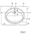
- Figure 1 shows a section of a plan view of one according to the invention Process manufactured arrangement 1 of a washstand.
- a Plate 10 is a, preferably ceramic, basin 20 with a basin body 21 and a cantilevered edge 22.
- the upper surface of the cantilever edge 22 lies in one plane with the flat surface 13 of a plate 10 or only by a few Millimeters below.
- the existing cantilever 22 is between its original large outer circumference 23 and his, the pelvic body 21 at least partially forming small outer circumference 24 according to the inventive method been docked in such a way that an insertion surface 25 was formed, which became an outer surface 12 of a cutout 11 in the plate 10 is suitable.
- the joint 14 can also be increased with permanently elastic to increase the sealing effect Sealing compound must be filled.
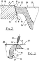
- FIG. 2 shows an enlarged illustration of the area of the parting line 14 according to FIG 1, with the size ratios not chosen to scale for clarity are.
- the lateral surface 12 of the cutout 11 and the insertion surface 25 of the Basin 20 are at an angle ⁇ or ⁇ to a lying plane 26 of the basin 20 or inclined to a flat surface 13 of the plate 10.
- the lateral surface 12 and the insertion surface 25 are tapered downwards trained and ideally congruent or only less than 1 mm offset in parallel so that the parting line 14 is as narrow as possible.
- the upper edge 27 of the insertion surface 25 is on the upper edge 15 of the cutout 11 a chamfer is formed.
- the lateral surface 12 and the insert surface 25 can have circular bases. It is also possible with the method according to the invention, cut surfaces manufacture that on an elliptical, polygonal or on any other Base area.
- the cut surfaces, i.e. the lateral surface 12 and the Insert surface 25 are essentially the contour of the to be installed Beckens 20 determined.
- the cantilever edge 22 of the basin 20 can be as far as possible be docked that the insertion surface 25 in the smaller outer circumference 24 of the Pelvic body 21 merges. It is also possible to create cut surfaces that not the outer contours, i.e. the original large outer circumference of the Cymbals correspond, for example in wave form.
- FIG. 3 shows a detailed view of a processed by means of high-pressure water jet 30 Cantilever edge 22 of a basin 20 or a cut when docking of the cantilever edge 22 of the basin 20.
- the one from the tip 32 of a cutting nozzle 31 high pressure water jet 30 exiting at a pressure of 2,000 to 5,000 bar loosens the smallest particles from the material that come with the water from the parting line 14 be rinsed.
- the cutting width can be adjusted via the cutting nozzle 31 and is preferably about 1.5 mm. When choosing the cutting width, there is an optimization between an economical cutting speed and sharp Make cutting edges.
- a ceramic, glazed sink 20 with an elliptical outer contour has an edge 22 projecting 3 cm from the lower pelvic body 21 on.
- the thickness of the cantilever edge 22 is approximately 16 mm.
- By delay in burning the ceramic is the top of the cantilever 22 over about 10% of the circumference by 1.5 mm compared to the rest of the rim 22 of the sink 20 deepened.
- the sink 20 is in a pneumatic clamp clamped, which clamps the basin 20 so that the area to be docked of the cantilever 22 is exposed.
- the clamping device is two-dimensional movable cross table of a CNC-controlled five-axis machine tool curious; excited.
- a cutting nozzle 31 is clamped into the machine tool.
- the tool guide is three-axis, so that the cutting nozzle 31 is vertical process, tilted and at this angle at the same time in relation to one imaginary cutting path center always aligned with the same orientation can be.
- a data record corresponding to the desired elliptical cutting line is shown in read the machine tool.
- the cutting nozzle 31 is at an angle inclined from 75 ° to the cross table and with this inclination to the center of the elliptical Railway aligned.
- the cutting nozzle is then lowered 31, so that the tip 32 of the cutting nozzle 31 is a distance of about 5 mm to the top of the cantilever edge 22.
- the pool 20 is then like this move that the cutting nozzle 31 is positioned above a starting point.
- Program control of the machine tool is preferably the cutting beam a high pressure water jet 30, turned on and along the predetermined elliptical Track led.
- the cutting speed is 15 to 20 cm / min.
- the compensation value corresponds to the cutting width minus 0.5 mm as tolerance value. It becomes the outer surface 12 of a section 11 is produced, the cutting surface of which is exactly parallel to the insertion surface 25 of the pelvis is 20.
- the upper edge 15 of the cutout 11 is chamfered to a width of 2 mm.
- the bevel and a 2 mm to 5 mm wide strip of the underlying lateral surface 12 are polished.
- the insertion surface 25 of the basin 20 is covered with a transparent sealant smeared.
- the sealant can be made on an acrylic or silicone basis be and is taking into account the compatibility with the materials the plate 10 and the basin 20 selected.
- the basin 20 is inserted into the cutout 11 and aligned so that the Lying plane 26 of the basin 20 parallel to the flat surface 13 of the plate 10 is aligned or congruent with this. If necessary, from the parting line 16 swelling, excess sealing compound is with a spatula decreased.
- the washstand is manufactured completed.
- the parting line 16 between basin 20 and plate 10 has one Width of only about 0.5 mm.
- the polished area of the The lateral surface 12 of the section 11 is visible.
- the upper edge 15 of the cutout 11 is the non-uniformity in the ceramic Basin 20 optically compensated and not perceived by the customer as a defect.
- a round ceramic sink 20 is made with the cutter Example 1 trimmed with a wave cut.
- a 2 cm thick polished granite slab 10 is on the same cutting line as a cutout 11 is cut into the wash basin 20.
- the high pressure water jet 30 cutting device is provided with abrasive cutting additives, to cut the cutting speed to 10 cm / min in the very hard material 15 cm / min to increase.
- the water pressure is around 3,200 bar.
- the basin 20 is inserted into the cutout 11.
- the parting line 16, the Width with 1.5 mm corresponds approximately to the width of the water jet, with a colored sealant filled to the unusual undulating contour to highlight the insert surface 25 optically.
- a hand-held cutting system For retrofitting a new wash basin 20 into an existing, a built-in washbasin 1, a hand-held cutting system is used. A preliminary opening is cut into the plate 10 to receive it of the smaller outer circumference 24 of the pelvic body 20 is suitable. The Basin 20 is inserted into the provisional opening so that the cantilever 22nd of the basin 20 rests on the flat surface 13 of the plate 10. The basin 20 is additionally trimmed from below. On the flat surface 13 of the plate 10, a cutting device is placed, in which a high-pressure water jet 30 aligned at an angle ⁇ or ⁇ less than 90 ° to the cutting plane is.
- the device has a feeler wheel at a distance from the cutting nozzle 31
- the cut is made manually, with the feeler wheel against the original larger outer edge 23 of the cantilever 22 is pressed so that results in a cutting line parallel to the original circumference of the pool.
- the cut is produced by the cantilever edge 22 of the basin 10 and table top 10 at the same time, so that compatible cutting surfaces 12, 25 are created here.
- the pool 20 is then lowered until the insertion surface of the basin 20 on the lateral surface 12 of the table top 10 rests.
- the method according to the invention is of course also in a further variant feasible with a cutting angle ⁇ or ⁇ of 90 ° or greater than 90 °, wherein the basin 20 then in a different manner than by means of a substantially wedge-shaped Connection must be arranged on the plate 10.
- the basin 20 can be supported separately, preferably in such a way that the lying level 26 of the pool 20 and the surface 13 of the plate 10 in one Love level.
- the compensation value can be set so that for example, a non-positive press fit occurs.
- the parting line 16 is then filled with a thixotropic polyurethane adhesive. After the adhesive has been crosslinked, the basin 20 is fixed in the plate 10.
- the method according to the invention is neither based on certain materials nor individual pool shapes limited. All pools with a cantilever are suitable Have edge.
Landscapes
- Engineering & Computer Science (AREA)
- Environmental & Geological Engineering (AREA)
- Health & Medical Sciences (AREA)
- Life Sciences & Earth Sciences (AREA)
- Hydrology & Water Resources (AREA)
- Public Health (AREA)
- Water Supply & Treatment (AREA)
- Processing Of Stones Or Stones Resemblance Materials (AREA)
- Sink And Installation For Waste Water (AREA)
- Devices For Post-Treatments, Processing, Supply, Discharge, And Other Processes (AREA)
Applications Claiming Priority (2)
| Application Number | Priority Date | Filing Date | Title |
|---|---|---|---|
| DE19819391 | 1998-04-30 | ||
| DE1998119391 DE19819391C2 (de) | 1998-04-30 | 1998-04-30 | Verfahren zum flächenbündigen Einbau eines keramischen Beckens in eine Tischplatte und danach hergestellter Waschtisch |
Publications (2)
| Publication Number | Publication Date |
|---|---|
| EP0953688A2 true EP0953688A2 (fr) | 1999-11-03 |
| EP0953688A3 EP0953688A3 (fr) | 2000-03-29 |
Family
ID=7866321
Family Applications (1)
| Application Number | Title | Priority Date | Filing Date |
|---|---|---|---|
| EP99107455A Withdrawn EP0953688A3 (fr) | 1998-04-30 | 1999-04-28 | Procédé pour le montage d'au moins une vasque, de préférence céramique, dans une plaque ainsi que dispositif formé par la vasque et la plaque |
Country Status (2)
| Country | Link |
|---|---|
| EP (1) | EP0953688A3 (fr) |
| DE (1) | DE19819391C2 (fr) |
Cited By (7)
| Publication number | Priority date | Publication date | Assignee | Title |
|---|---|---|---|---|
| FR2837510A1 (fr) * | 2002-03-25 | 2003-09-26 | Chene Vert | Procede d'integration d'une vasque a un plan recepteur par clipsage, vasque et plan recepteur, dissocies ou solidarises |
| EP1184519A3 (fr) * | 2000-08-17 | 2004-07-14 | Carol Voegeli | Evier |
| WO2004073945A1 (fr) * | 2003-02-18 | 2004-09-02 | Merhav - Designer Building Products Ltd. | Evier de cuisine |
| ITMI20090613A1 (it) * | 2009-04-16 | 2010-10-17 | Euro Porfidi S P A | Lavello ad incasso. |
| BE1019699A3 (nl) * | 2010-12-13 | 2012-10-02 | United Stone Products Bvba | Object uit steen en werkwijze om een dergelijk object te maken. |
| CN114182792A (zh) * | 2022-01-06 | 2022-03-15 | 广东宾丽卫浴有限公司 | 一种斜面连接式台下洗手盆及其制作方法 |
| CN115741942A (zh) * | 2022-11-25 | 2023-03-07 | 广东尚高科技有限公司 | 洗手盆制造方法、洗手盆及具有其的浴室柜 |
Citations (1)
| Publication number | Priority date | Publication date | Assignee | Title |
|---|---|---|---|---|
| DE3042215A1 (de) | 1980-11-08 | 1982-06-16 | Metallwerke Gebr. Seppelfricke Gmbh & Co, 4650 Gelsenkirchen | Keramischer waschtisch fuer grosswaschtischanlagen |
Family Cites Families (7)
| Publication number | Priority date | Publication date | Assignee | Title |
|---|---|---|---|---|
| US4992011A (en) * | 1989-04-06 | 1991-02-12 | Fred M. Velepec Co., Inc. | Cutting and shaping tool |
| IL97506A0 (en) * | 1991-03-11 | 1992-06-21 | Moshav Shitufi Regba | Flush-mount sink assembly method |
| DE4411263C2 (de) * | 1994-03-31 | 1998-09-17 | Esab Hancock Gmbh | Verfahren zur Überprüfung der Führungsgenauigkeit einer Brennschneidmaschine und Anordnung zur Durchführung des Verfahrens |
| DE4432014A1 (de) * | 1994-09-08 | 1996-03-14 | Foracon Maschinen Und Anlagenb | Verfahren zum Anbringen von Einsatzteilen |
| DE4438247C2 (de) * | 1994-10-26 | 2001-08-30 | Opel Adam Ag | Verfahren zum Anpassen einer Zylinderkopfdichtung an einen Zylinderblock einer Brennkraftmaschine |
| DE19644544C1 (de) * | 1996-10-26 | 1998-04-02 | Reuter Paul Gmbh & Co Kg | Sprossenhohlprofilmaterial und Sprossengitter sowie Herstellverfahren |
| DE19711512C1 (de) * | 1997-03-19 | 1998-10-15 | Foracon Maschinen Und Anlagenb | Wasserstrahlschneiden von Ausschnitten in Rohrwandungen |
-
1998
- 1998-04-30 DE DE1998119391 patent/DE19819391C2/de not_active Expired - Fee Related
-
1999
- 1999-04-28 EP EP99107455A patent/EP0953688A3/fr not_active Withdrawn
Patent Citations (1)
| Publication number | Priority date | Publication date | Assignee | Title |
|---|---|---|---|---|
| DE3042215A1 (de) | 1980-11-08 | 1982-06-16 | Metallwerke Gebr. Seppelfricke Gmbh & Co, 4650 Gelsenkirchen | Keramischer waschtisch fuer grosswaschtischanlagen |
Cited By (8)
| Publication number | Priority date | Publication date | Assignee | Title |
|---|---|---|---|---|
| EP1184519A3 (fr) * | 2000-08-17 | 2004-07-14 | Carol Voegeli | Evier |
| FR2837510A1 (fr) * | 2002-03-25 | 2003-09-26 | Chene Vert | Procede d'integration d'une vasque a un plan recepteur par clipsage, vasque et plan recepteur, dissocies ou solidarises |
| WO2003080949A1 (fr) * | 2002-03-25 | 2003-10-02 | Chene Vert | Procede d'integration dune vasque a un plan recepteur par clipsage, vasque et plan recepteur, dissocies ou solidarises |
| WO2004073945A1 (fr) * | 2003-02-18 | 2004-09-02 | Merhav - Designer Building Products Ltd. | Evier de cuisine |
| ITMI20090613A1 (it) * | 2009-04-16 | 2010-10-17 | Euro Porfidi S P A | Lavello ad incasso. |
| BE1019699A3 (nl) * | 2010-12-13 | 2012-10-02 | United Stone Products Bvba | Object uit steen en werkwijze om een dergelijk object te maken. |
| CN114182792A (zh) * | 2022-01-06 | 2022-03-15 | 广东宾丽卫浴有限公司 | 一种斜面连接式台下洗手盆及其制作方法 |
| CN115741942A (zh) * | 2022-11-25 | 2023-03-07 | 广东尚高科技有限公司 | 洗手盆制造方法、洗手盆及具有其的浴室柜 |
Also Published As
| Publication number | Publication date |
|---|---|
| DE19819391A1 (de) | 1999-11-11 |
| EP0953688A3 (fr) | 2000-03-29 |
| DE19819391C2 (de) | 2002-11-07 |
Similar Documents
| Publication | Publication Date | Title |
|---|---|---|
| DE4135573A1 (de) | Verfahren und vorrichtung zum einbringen von oberflaechenkanaelen in plattenmaterial aus weichem werkstoff und verwendung einer vorrichtung | |
| DE69222553T2 (de) | Verfahren zum Einbau einer versenkten Spüle | |
| DE3516619A1 (de) | Verfahren und vorrichtung zum gewindeschleifen | |
| EP0953688A2 (fr) | Procédé pour le montage d'au moins une vasque, de préférence céramique, dans une plaque ainsi que dispositif formé par la vasque et la plaque | |
| DE19855803B4 (de) | Verfahren und Vorrichtung zum Herstellen einer Fase oder einer Keilnut an einem Werkstück | |
| EP1323508B1 (fr) | Machine pour affleurer des bandes de bords | |
| EP1537970B1 (fr) | Dispositif d'ébarbage | |
| DE69022741T2 (de) | Verfahren und vorrichtung zum spalten von laminierten mineralblöcken. | |
| EP1116531B1 (fr) | Procédé de fabrication de tôles à bords biseautes | |
| DE10258567B4 (de) | Vorrichtung zur Stanzbearbeitung einer Leiste, insbesondere einer Sockelleiste | |
| EP1129835A2 (fr) | Dispositif pour casser des carreaux | |
| EP1375038A1 (fr) | Plaquette amovible à tronçonner | |
| DE3909709A1 (de) | Vorrichtung zur endbearbeitung der randzone von tafeln, insbesondere von tafeln fuer die innenverkleidung von kraftfahrzeugen | |
| DE2834232A1 (de) | Vorrichtung zum brechen keramischer verkleidungsstuecke | |
| CH685930A5 (de) | Fasenschleifkopf fur die Steinbearbeitung fur den Einsatz auf Kantenschleifmaschinen. | |
| EP0062953B1 (fr) | Dispositif pour le sciage de pierres naturelles ou artificielles | |
| DE102008013008B4 (de) | Schleifwerkzeug zum Erzeugen im Querschnitt T-förmiger Nuten, bogenförmige T-förmig hinterschnittene Nut sowie Verfahren und angetriebens Werkzeug zur Herstellung einer derartigen Nut | |
| DE4310565C2 (de) | Schneidwerkzeug mit Schneidplatte und Schneidplattenhalter | |
| DE19714483A1 (de) | Leuchtenabdeckung | |
| DE7906841U1 (de) | Schneidvorrichtung zum zerschneiden von stein- und keramikplatten | |
| DE10130463A1 (de) | Verfahren zur Herstellung von Korkplatten | |
| DE9101520U1 (de) | Schneidvorrichtung | |
| DE102021100726A1 (de) | Fliesenschneider | |
| DE4334584A1 (de) | Verfahren zur Herstellung von Paneelen oder dergleichen | |
| DE29618095U1 (de) | Führungseinrichtung für Nutfräsen |
Legal Events
| Date | Code | Title | Description |
|---|---|---|---|
| PUAI | Public reference made under article 153(3) epc to a published international application that has entered the european phase |
Free format text: ORIGINAL CODE: 0009012 |
|
| AK | Designated contracting states |
Kind code of ref document: A2 Designated state(s): AT BE CH CY DE DK ES FI FR GB GR IE IT LI LU MC NL PT SE |
|
| AX | Request for extension of the european patent |
Free format text: AL;LT;LV;MK;RO;SI |
|
| PUAL | Search report despatched |
Free format text: ORIGINAL CODE: 0009013 |
|
| AK | Designated contracting states |
Kind code of ref document: A3 Designated state(s): AT BE CH CY DE DK ES FI FR GB GR IE IT LI LU MC NL PT SE |
|
| AX | Request for extension of the european patent |
Free format text: AL;LT;LV;MK;RO;SI |
|
| AKX | Designation fees paid | ||
| REG | Reference to a national code |
Ref country code: DE Ref legal event code: 8566 |
|
| STAA | Information on the status of an ep patent application or granted ep patent |
Free format text: STATUS: THE APPLICATION IS DEEMED TO BE WITHDRAWN |
|
| 18D | Application deemed to be withdrawn |
Effective date: 20000930 |