EP0953711A2 - Method of manufacturing a profile for windows or doors - Google Patents
Method of manufacturing a profile for windows or doors Download PDFInfo
- Publication number
- EP0953711A2 EP0953711A2 EP99107844A EP99107844A EP0953711A2 EP 0953711 A2 EP0953711 A2 EP 0953711A2 EP 99107844 A EP99107844 A EP 99107844A EP 99107844 A EP99107844 A EP 99107844A EP 0953711 A2 EP0953711 A2 EP 0953711A2
- Authority
- EP
- European Patent Office
- Prior art keywords
- profile
- web
- tool
- webs
- forming
- Prior art date
- Legal status (The legal status is an assumption and is not a legal conclusion. Google has not performed a legal analysis and makes no representation as to the accuracy of the status listed.)
- Granted
Links
- 238000004519 manufacturing process Methods 0.000 title abstract description 4
- 238000000034 method Methods 0.000 claims abstract description 17
- 238000001816 cooling Methods 0.000 claims abstract description 8
- 239000000463 material Substances 0.000 claims description 8
- 238000003466 welding Methods 0.000 claims description 7
- 239000004033 plastic Substances 0.000 description 7
- 230000004888 barrier function Effects 0.000 description 6
- 238000009413 insulation Methods 0.000 description 5
- 238000001125 extrusion Methods 0.000 description 4
- 230000000694 effects Effects 0.000 description 3
- 238000000465 moulding Methods 0.000 description 3
- 238000003860 storage Methods 0.000 description 3
- 229910000831 Steel Inorganic materials 0.000 description 2
- 238000010438 heat treatment Methods 0.000 description 2
- 230000002787 reinforcement Effects 0.000 description 2
- 239000010959 steel Substances 0.000 description 2
- XLYOFNOQVPJJNP-UHFFFAOYSA-N water Substances O XLYOFNOQVPJJNP-UHFFFAOYSA-N 0.000 description 2
- 238000009825 accumulation Methods 0.000 description 1
- 230000001427 coherent effect Effects 0.000 description 1
- 238000010276 construction Methods 0.000 description 1
- 239000003000 extruded plastic Substances 0.000 description 1
- 239000011888 foil Substances 0.000 description 1
- 239000011521 glass Substances 0.000 description 1
- 230000017525 heat dissipation Effects 0.000 description 1
- 239000011343 solid material Substances 0.000 description 1
Images

Classifications
-
- E—FIXED CONSTRUCTIONS
- E06—DOORS, WINDOWS, SHUTTERS, OR ROLLER BLINDS IN GENERAL; LADDERS
- E06B—FIXED OR MOVABLE CLOSURES FOR OPENINGS IN BUILDINGS, VEHICLES, FENCES OR LIKE ENCLOSURES IN GENERAL, e.g. DOORS, WINDOWS, BLINDS, GATES
- E06B3/00—Window sashes, door leaves, or like elements for closing wall or like openings; Layout of fixed or moving closures, e.g. windows in wall or like openings; Features of rigidly-mounted outer frames relating to the mounting of wing frames
- E06B3/04—Wing frames not characterised by the manner of movement
- E06B3/06—Single frames
- E06B3/08—Constructions depending on the use of specified materials
- E06B3/20—Constructions depending on the use of specified materials of plastics
- E06B3/22—Hollow frames
-
- B—PERFORMING OPERATIONS; TRANSPORTING
- B29—WORKING OF PLASTICS; WORKING OF SUBSTANCES IN A PLASTIC STATE IN GENERAL
- B29C—SHAPING OR JOINING OF PLASTICS; SHAPING OF MATERIAL IN A PLASTIC STATE, NOT OTHERWISE PROVIDED FOR; AFTER-TREATMENT OF THE SHAPED PRODUCTS, e.g. REPAIRING
- B29C48/00—Extrusion moulding, i.e. expressing the moulding material through a die or nozzle which imparts the desired form; Apparatus therefor
- B29C48/03—Extrusion moulding, i.e. expressing the moulding material through a die or nozzle which imparts the desired form; Apparatus therefor characterised by the shape of the extruded material at extrusion
- B29C48/09—Articles with cross-sections having partially or fully enclosed cavities, e.g. pipes or channels
- B29C48/11—Articles with cross-sections having partially or fully enclosed cavities, e.g. pipes or channels comprising two or more partially or fully enclosed cavities, e.g. honeycomb-shaped
-
- B—PERFORMING OPERATIONS; TRANSPORTING
- B29—WORKING OF PLASTICS; WORKING OF SUBSTANCES IN A PLASTIC STATE IN GENERAL
- B29C—SHAPING OR JOINING OF PLASTICS; SHAPING OF MATERIAL IN A PLASTIC STATE, NOT OTHERWISE PROVIDED FOR; AFTER-TREATMENT OF THE SHAPED PRODUCTS, e.g. REPAIRING
- B29C48/00—Extrusion moulding, i.e. expressing the moulding material through a die or nozzle which imparts the desired form; Apparatus therefor
- B29C48/03—Extrusion moulding, i.e. expressing the moulding material through a die or nozzle which imparts the desired form; Apparatus therefor characterised by the shape of the extruded material at extrusion
- B29C48/12—Articles with an irregular circumference when viewed in cross-section, e.g. window profiles
-
- B—PERFORMING OPERATIONS; TRANSPORTING
- B29—WORKING OF PLASTICS; WORKING OF SUBSTANCES IN A PLASTIC STATE IN GENERAL
- B29C—SHAPING OR JOINING OF PLASTICS; SHAPING OF MATERIAL IN A PLASTIC STATE, NOT OTHERWISE PROVIDED FOR; AFTER-TREATMENT OF THE SHAPED PRODUCTS, e.g. REPAIRING
- B29C48/00—Extrusion moulding, i.e. expressing the moulding material through a die or nozzle which imparts the desired form; Apparatus therefor
- B29C48/15—Extrusion moulding, i.e. expressing the moulding material through a die or nozzle which imparts the desired form; Apparatus therefor incorporating preformed parts or layers, e.g. extrusion moulding around inserts
-
- B—PERFORMING OPERATIONS; TRANSPORTING
- B29—WORKING OF PLASTICS; WORKING OF SUBSTANCES IN A PLASTIC STATE IN GENERAL
- B29C—SHAPING OR JOINING OF PLASTICS; SHAPING OF MATERIAL IN A PLASTIC STATE, NOT OTHERWISE PROVIDED FOR; AFTER-TREATMENT OF THE SHAPED PRODUCTS, e.g. REPAIRING
- B29C48/00—Extrusion moulding, i.e. expressing the moulding material through a die or nozzle which imparts the desired form; Apparatus therefor
- B29C48/25—Component parts, details or accessories; Auxiliary operations
- B29C48/30—Extrusion nozzles or dies
- B29C48/32—Extrusion nozzles or dies with annular openings, e.g. for forming tubular articles
- B29C48/34—Cross-head annular extrusion nozzles, i.e. for simultaneously receiving moulding material and the preform to be coated
-
- E—FIXED CONSTRUCTIONS
- E06—DOORS, WINDOWS, SHUTTERS, OR ROLLER BLINDS IN GENERAL; LADDERS
- E06B—FIXED OR MOVABLE CLOSURES FOR OPENINGS IN BUILDINGS, VEHICLES, FENCES OR LIKE ENCLOSURES IN GENERAL, e.g. DOORS, WINDOWS, BLINDS, GATES
- E06B3/00—Window sashes, door leaves, or like elements for closing wall or like openings; Layout of fixed or moving closures, e.g. windows in wall or like openings; Features of rigidly-mounted outer frames relating to the mounting of wing frames
- E06B3/04—Wing frames not characterised by the manner of movement
- E06B3/06—Single frames
- E06B3/08—Constructions depending on the use of specified materials
- E06B3/20—Constructions depending on the use of specified materials of plastics
- E06B3/22—Hollow frames
- E06B3/221—Hollow frames with the frame member having local reinforcements in some parts of its cross-section or with a filled cavity
- E06B3/222—Hollow frames with the frame member having local reinforcements in some parts of its cross-section or with a filled cavity with internal prefabricated reinforcing section members inserted after manufacturing of the hollow frame
-
- B—PERFORMING OPERATIONS; TRANSPORTING
- B29—WORKING OF PLASTICS; WORKING OF SUBSTANCES IN A PLASTIC STATE IN GENERAL
- B29L—INDEXING SCHEME ASSOCIATED WITH SUBCLASS B29C, RELATING TO PARTICULAR ARTICLES
- B29L2031/00—Other particular articles
- B29L2031/001—Profiled members, e.g. beams, sections
- B29L2031/003—Profiled members, e.g. beams, sections having a profiled transverse cross-section
- B29L2031/005—Profiled members, e.g. beams, sections having a profiled transverse cross-section for making window frames
-
- E—FIXED CONSTRUCTIONS
- E06—DOORS, WINDOWS, SHUTTERS, OR ROLLER BLINDS IN GENERAL; LADDERS
- E06B—FIXED OR MOVABLE CLOSURES FOR OPENINGS IN BUILDINGS, VEHICLES, FENCES OR LIKE ENCLOSURES IN GENERAL, e.g. DOORS, WINDOWS, BLINDS, GATES
- E06B3/00—Window sashes, door leaves, or like elements for closing wall or like openings; Layout of fixed or moving closures, e.g. windows in wall or like openings; Features of rigidly-mounted outer frames relating to the mounting of wing frames
- E06B3/04—Wing frames not characterised by the manner of movement
- E06B3/06—Single frames
- E06B3/08—Constructions depending on the use of specified materials
- E06B3/20—Constructions depending on the use of specified materials of plastics
- E06B3/22—Hollow frames
- E06B3/221—Hollow frames with the frame member having local reinforcements in some parts of its cross-section or with a filled cavity
- E06B3/222—Hollow frames with the frame member having local reinforcements in some parts of its cross-section or with a filled cavity with internal prefabricated reinforcing section members inserted after manufacturing of the hollow frame
- E06B2003/224—Hollow frames with the frame member having local reinforcements in some parts of its cross-section or with a filled cavity with internal prefabricated reinforcing section members inserted after manufacturing of the hollow frame with reinforcing plastic section members
-
- E—FIXED CONSTRUCTIONS
- E06—DOORS, WINDOWS, SHUTTERS, OR ROLLER BLINDS IN GENERAL; LADDERS
- E06B—FIXED OR MOVABLE CLOSURES FOR OPENINGS IN BUILDINGS, VEHICLES, FENCES OR LIKE ENCLOSURES IN GENERAL, e.g. DOORS, WINDOWS, BLINDS, GATES
- E06B3/00—Window sashes, door leaves, or like elements for closing wall or like openings; Layout of fixed or moving closures, e.g. windows in wall or like openings; Features of rigidly-mounted outer frames relating to the mounting of wing frames
- E06B3/04—Wing frames not characterised by the manner of movement
- E06B3/06—Single frames
- E06B3/08—Constructions depending on the use of specified materials
- E06B3/20—Constructions depending on the use of specified materials of plastics
- E06B3/205—Constructions depending on the use of specified materials of plastics moulded or extruded around a core
Definitions
- the invention relates to a method for producing a profile for windows or Doors according to the preamble of claim 1.
- the present Invention relates specifically to the design of the to be used for this Profiles.
- Hollow profiles with thin-walled hard PVC webs are known. Because of through the webs formed remain in the hollow air that is opposite the adjacent wall has an insulating effect.
- the chambers are designed to provide thermal insulation effect from the outside against the inside of the profile.
- window profiles are 3-chamber systems
- high-quality window profiles have recently been equipped with 4-chamber systems.
- a hollow profile is already from the example EP 0 828 052 A2 known.
- a barrier film during the extrusion process of the hollow profile into the correspondingly formed chambers to bring in the profile.
- the barrier film held on a reel supplied through a corresponding opening in the extruder nozzle, whereby a positive connection between the plastic plastic material and the barrier film is created.
- the object of the invention is therefore a method for producing a profile for Give windows or doors to hand, while achieving high molding speeds Profiles for windows or doors of the type specified at the beginning are malleable.
- the one emerging from the first extruder line can Web before entering the tool, in which the outer or inner surface of the outer profile part is formed, as far as cooled, on the one hand for good welding in the edge area of the at least one web is necessary, but without the problems of insufficient heat dissipation in To have to buy.
- the at least one web can advantageously be made of a foamed material consist. This allows increased thermal insulation in a simple manner reach without additional webs or chambers in the window profile must be introduced.
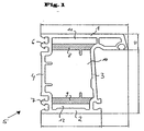
- Fig. 1 shows a cross section through the profile according to the invention.
- the profile exists of an outer surface 1 and an inner surface 2 with a glazing side 3 and a wall side 4 form the profile 5.
- On the wall side 4 are grid lugs 6 and 7 are provided, which can be snapped into a secondary profile.
- the webs 8, 9 consist of a foamed material.
- Material used is a hard PVC plastic.
- Fig. 2 shows a cross section through a tool for producing the invention 1.
- the tool 20 consists of a heart curve 21, in a connection 22 is introduced for an extruder.
- the heart curve has openings 23, 24, in each of which consists of a foamed material Footbridge can be inserted.
- the heart curve 21 is via screws 26 with a Storage ring 25 screwed.
- the mandrel 27 which over Screws 28 is screwed to the heart curve 21.
- a head plate 29 which consists of a tightening plate 31 and two further plates 32, 33 there.
- each made of a foamed hard PVC plastic via the openings 23, 24 existing webs introduced.
- the openings 23, 24 there could be either another extruder line or a magazine that is already finished extruded webs.
- the inserted bars pass through the tool and weld behind the plate 33 with that emerging from the tool Profile.
- the exit temperature of the webs from the tool must be be sufficient so that the webs still weld to the profile, however outlet temperature must not be so high that the profile due to the inserted webs heats up too much and warps as a result.
- Even with one Water cooling of the profile behind the tool is in fact not possible, either cool the ridges sufficiently quickly, as these are suitable for water cooling are inaccessible inside the profile.
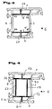
- Fig. 3 is a profile 5 with an outer surface 1 and an inner surface 2 of a glazing side 3 and a wall side 4 shown.
- the provided in this profile Crosspieces 8 'and 9' are on their side edges 50 and 52 or 54 and 56 one side with the wall side 4 and the other with the glazing side 3 of the Profiles 5 welded.
- the webs 8 'and 9' have an approximate web 58 or 60, which runs perpendicular to them in the middle.
- the jetty 58 is welded with its free side edge to the outer surface 1 of the profile 5 and the web 60 is welded to the inner surface 2 with its free side edge.
- FIG. 4 shows a profile 5 that is slightly different from that according to FIG. 3 deviates.
- the webs 8 'and 9' are each again through transverse Walls 62 and 64 connected to each other in such a way that a coherent overall Inner profile results from the webs 8 'and 9' with their vertical Web 58 and 60 and the connecting webs 62 and 64.
- the closed inner profile according to FIG. 4 is also in a first extrusion line extruded and finally cooled. It then becomes a profile Tool introduced, in which the profile 5 with the outer surface 1 and the inner surface 2 and the glazing side surface 3 or the wall side surface 4 is extruded.
- the side edges of the inner profile are reached using a The hot air blower is heated up again so that it can be securely welded becomes.
- heating cartridges could also be used for heating the side edges are provided.
Landscapes
- Engineering & Computer Science (AREA)
- Mechanical Engineering (AREA)
- Civil Engineering (AREA)
- Structural Engineering (AREA)
- Manufacturing & Machinery (AREA)
- Extrusion Moulding Of Plastics Or The Like (AREA)
- Shaping Of Tube Ends By Bending Or Straightening (AREA)
- Blow-Moulding Or Thermoforming Of Plastics Or The Like (AREA)
- Securing Of Glass Panes Or The Like (AREA)
- Re-Forming, After-Treatment, Cutting And Transporting Of Glass Products (AREA)
- Molding Of Porous Articles (AREA)
- Lighters Containing Fuel (AREA)
- Automobile Manufacture Line, Endless Track Vehicle, Trailer (AREA)
- Catalysts (AREA)
- Glass Compositions (AREA)
- Wing Frames And Configurations (AREA)
Abstract
Die Erfindung betrifft ein Verfahren zum Herstellen eines Profils für Fenster oder Türen mit einer Außenfläche und mit einer Innenfläche und mit mindestens einem Steg, der zwischen der Außenfläche und der Innenfläche eine Kammer abtrennt. Erfindungsgemäß wird bei diesem Verfahren der mindestens eine Steg in einer ersten Extruderlinie extrudiert und nach zumindest teilweisem Abkühlen in ein das Profil formendes Werkzeug geführt, in welchem dann der mindestens eine Steg mit dem Profil verschweißt wird. <IMAGE>The invention relates to a method for producing a profile for windows or doors with an outer surface and with an inner surface and with at least one web that separates a chamber between the outer surface and the inner surface. According to the invention, in this method the at least one web is extruded in a first extruder line and, after at least partial cooling, is guided into a tool that forms the profile, in which the at least one web is then welded to the profile. <IMAGE>
Description
Die Erfindung betrifft ein Verfahren zum Herstellen eines Profils für Fenster oder Türen nach dem Oberbegriff des Anspruchs 1.The invention relates to a method for producing a profile for windows or Doors according to the preamble of claim 1.
Bei Fenstern und Türen ist es grundsätzlich wünschenswert, eine hohe Wärme- und Schalldämmung zu erzielen. Hierbei sind sowohl die Konstruktion der Glasflächen, als auch die Ausgestaltung der Rahmenprofile von Bedeutung. Die vorliegende Erfindung bezieht sich speziell auf die Ausgestaltung der hierfür zu verwendenden Profile.With windows and doors it is generally desirable to have a high heat and To achieve sound insulation. Both the construction of the glass surfaces, as well as the design of the frame profiles. The present Invention relates specifically to the design of the to be used for this Profiles.
Bekannt sind Hohlprofile mit dünnwandigen Hart-PVC-Stegen. Aufgrund der durch die Stege gebildeten Kammern verbleibt in dem Hohlprofil Luft, die gegenüber der angrenzenden Wandung isolierend wirkt. Die Kammern sollen eine Wärmedämmung von der Außenseite gegenüber der Innenseite des Profiles bewirken. Für Fensterprofile sind beispielsweise 3-Kammer-Systeme üblich, hochwertige Fensterprofile sind seit neustem mit 4-Kammer-Systemen ausgestattet. Hollow profiles with thin-walled hard PVC webs are known. Because of through the webs formed remain in the hollow air that is opposite the adjacent wall has an insulating effect. The chambers are designed to provide thermal insulation effect from the outside against the inside of the profile. For For example, window profiles are 3-chamber systems, high-quality window profiles have recently been equipped with 4-chamber systems.
Problematisch ist allerdings die Tatsache, daß die Stege bzw. das Vollmaterial der Stege eine Wärmeleitung zwischen den Kammern zuläßt, die beträchtlich höher als die Wärmeleitung von Luft ist. Zwar ließe sich durch mehrere Kammern auch eine höhere Wärmedämmung erreichen, allerdings ist die Anzahl der in das Profil einzubringenden Kammern durch die äußere Geometrie sowie durch weitere in das Profil einzubringende Versteifungen aus Stahl begrenzt. Außerdem ist das Einbringen weiterer Kammern kostenaufwendig, so daß auch aus diesem Grund die Anzahl der Kammern nicht beliebig gesteigert werden soll.The problem, however, is the fact that the webs or the solid material of the Bridges allow heat conduction between the chambers that is considerably higher than is the heat conduction of air. It would be possible to have one through several chambers achieve higher thermal insulation, however, the number of those to be incorporated into the profile Chambers through the outer geometry as well as through others in the profile Limited reinforcements made of steel. In addition, the introduction other chambers costly, so that for this reason the number the chambers should not be increased arbitrarily.
Ein Hohlprofil, wie es zuvor beschrieben wurde, ist beispielsweise schon aus der EP 0 828 052 A2 bekannt. Dort wird bereits beschrieben, eine Sperrfolie während des Extrudiervorganges des Hohlprofils in die entsprechend gebildeten Kammern im Profil einzubringen. Dabei wird die auf einer Haspel vorrätig gehaltene Sperrfolie durch einen entsprechenden Durchbruch in der Extruderdüse zugeführt, wodurch eine kraftschlüssige Verbindung zwischen dem plastischen Kunststoffmaterial und der Sperrfolie entsteht.A hollow profile, as described above, is already from the example EP 0 828 052 A2 known. There is already described a barrier film during the extrusion process of the hollow profile into the correspondingly formed chambers to bring in the profile. The barrier film held on a reel supplied through a corresponding opening in the extruder nozzle, whereby a positive connection between the plastic plastic material and the barrier film is created.
Mit diesem Verfahren, bei dem die Sperrfolie vorgefertigt von einer Haspel abgezogen und dem das Profil bildenden Extruder zugeführt wird, mag aufgrund der vergleichsweise dünnen Wandung der Sperrfolie ein hinreichend gutes Verschweißen im Randbereich der Sperrfolie mit dem Profil möglich sein. Bei dickeren Folien bzw. bei dickeren wandartigen Stegen ist ein sicheres Verschweißen allerdings nicht mehr gewährleistet.Using this process, in which the barrier film is prefabricated pulled off a reel and the extruder forming the profile may be due to the comparatively thin wall of the barrier film a sufficiently good welding be possible in the edge area of the barrier film with the profile. With thicker foils or with thicker wall-like webs, however, secure welding is not more guaranteed.
Zur Abhilfe könnte man auf die Idee kommen, an einem Werkzeug mehrere Extrudierlinien direkt anzuschließen, die einerseits die äußere Umhüllung für jedes Profil bilden und andererseits den das Profil unterteilenden Steg. Formt man allerdings in dem Werkzeug sowohl den äußeren Profilteil wie auch den im Inneren des Profils angeordneten Steg, so ergibt sich schon bei vergleichsweise niedrigen Formgeschwindigkeiten das Problem des gleichmäßigen Abkühlens des extrudierten Kunststoffs. Während im Außenprofilbereich ein vergleichsweise schnelles Abkühlen erfolgt, vermag die Wärme von dem im Werkzeug gebildeten inneren Steg nur ungenügend abgeführt werden, so daß es zu Verformungen und Verwerfungen des Gesamtprofils kommt.To remedy this, one could come up with the idea of using several extrusion lines on one tool directly connect the one hand the outer wrapping for each profile form and on the other hand the web dividing the profile. However, one forms in the tool both the outer profile part and the inside of the profile arranged web, this results even at comparatively low molding speeds the problem of uniform cooling of the extruded Plastic. Comparatively quick cooling in the outer profile area takes place, the heat from the inner web formed in the tool can only insufficiently dissipated, so that there is deformation and warping of the Overall profile is coming.
Aufgabe der Erfindung ist es daher, ein Verfahren zur Herstellung eines Profils für Fenster oder Türen an die Hand zu geben, bei dem unter Erreichen hoher Formgeschwindigkeiten Profile für Fenster oder Türen der eingangs angegebenen Art formbar sind.The object of the invention is therefore a method for producing a profile for Give windows or doors to hand, while achieving high molding speeds Profiles for windows or doors of the type specified at the beginning are malleable.
Erfindungsgemäß wird diese Aufgabe ausgehend von einem gattungsgemäßen Verfahren durch die Kombination mit den Merkmalen nach dem kennzeichnenden Teil des Anspruchs 1 gelöst. Dabei werden folgende Verfahrensschritte durchgeführt:
- Extrudieren des mindestens einen Steges mit einer ersten Extruderlinie,
- zumindest teilweises Abkühlen des mindestens einen aus der Extruderlinie austretenden Steg,
- Einführen des mindestens einen Steges in ein das Profil formendes Werkzeug,
- Bilden des Profils mit Außen- und Innenfläche in dem mit einer zweiten Extruderlinie verbundenen Werkzeug und
- Verschweißen des mindestens einen Steges mit dem im Werkzeug die Außen- bzw. Innenfläche bildenden Profilteil beim Austreten aus dem Werkzeug.
- Extruding the at least one web with a first extruder line,
- at least partially cooling the at least one web emerging from the extruder line,
- Inserting the at least one web into a tool forming the profile,
- Forming the profile with outer and inner surface in the tool connected with a second extruder line and
- Welding the at least one web to the profile part forming the outer or inner surface in the tool as it exits the tool.
Durch das erfindungsgemäße Verfahren kann der aus der ersten Extruderlinie austretende Steg vor dem Eintritt in das Werkzeug, in welchem die Außen- bzw. Innenfläche des äußeren Profilteils gebildet wird, soweit abgekühlt werden, wie dies einerseits zum guten Verschweißen im Randbereich des mindestens einen Steges notwendig ist, ohne aber die Probleme des unzureichenden Wärmeabtransports in Kauf nehmen zu müssen.By means of the method according to the invention, the one emerging from the first extruder line can Web before entering the tool, in which the outer or inner surface of the outer profile part is formed, as far as cooled, on the one hand for good welding in the edge area of the at least one web is necessary, but without the problems of insufficient heat dissipation in To have to buy.
Mittels dieses Verfahrens lassen sich die üblichen Formgeschwindigkeiten komplexer Fenster- bzw. Türprofile der eingangs angegebenen Art zumindest verdoppeln.With this method, the usual molding speeds can be made more complex At least double window or door profiles of the type specified at the beginning.
Bevorzugte Ausgestaltungen des erfindungsgemäßen Verfahrens ergeben sich aus den sich an den Hauptanspruch anschließenden Unteransprüchen. Demnach kann der mindestens eine Steg durch das Werkzeug auf eine Temperatur aufgewärmt sein, bei der der Steg noch eine genügend hohe Festigkeit aufweist, um mit dem Profil verschweißbar zu sein.Preferred configurations of the method according to the invention result from the subclaims following the main claim. So can the at least one web is warmed to a temperature by the tool be, in which the web still has a high enough strength to with the Profile to be weldable.
Weiterhin kann der mindestens eine Steg vorteilhaft aus einem geschäumten Material bestehen. Hiermit läßt sich in einfacher Weise eine erhöhte Wärmedämmung erreichen, ohne daß noch weitere zusätzliche Stege oder Kammern in das Fensterprofil eingebracht werden müssen.Furthermore, the at least one web can advantageously be made of a foamed material consist. This allows increased thermal insulation in a simple manner reach without additional webs or chambers in the window profile must be introduced.
Aus Festigkeitsgründen kann es erwünscht sein, den mindestens einen Steg soweit abzukühlen, daß ein Verschweißen nur noch schwierig möglich ist. Gerade für diesen Anwendungsfall ist es gemäß einer weiteren Ausgestaltung des Verfahrens vorgesehen, den Randbereich des mindestens einen Steges, entlang dessen dieser verschweißt werden soll, soweit aufzuheizen, daß eine gute Verschweißbarkeit zwischen dem die Außen- bzw. Innenfläche bildenden Profilteil und dem mindestens einen Steg erreicht wird.For reasons of strength, it may be desirable to extend the at least one web as far to cool down that welding is only possible with difficulty. Especially for this one It is used according to a further embodiment of the method provided, the edge region of the at least one web, along which this should be welded to the extent that it can be easily welded between the profile part forming the outer or inner surface and the at least a footbridge is reached.
Werterhin kann anstelle eines oder mehrerer Stege auch ein komplexeres Innenprofil mit dem die Außen- bzw. Innenfläche bildenden Profilteil verschweißbar sein.You can also use a more complex inner profile instead of one or more webs be weldable to the profile part forming the outer or inner surface.
Weitere Vorteile und Einzelheiten der Erfindung ergeben sich aus einem in der Zeichnung dargestellten Ausführungsbeispiel. In dieser zeigt:
- Fig. 1:
- Einen Querschnitt durch ein mit dem erfindungsgemäßen Verfahren hergestelltes Profil,
- Fig. 2:
- einen Querschnitt durch ein Werkzeug zum Herstellen des erfindungsgemäßen Profils nach Fig. 1,
- Fig. 3:
- einen weiteren Querschnitt durch ein gemäß einem erfindungsgemäßen Verfahren hergestellten Profil und
- Fig. 4:
- einen dritten Querschnitt eines durch das erfindungsgemäße Verfahren hergestellten Profils.
- Fig. 1:
- A cross section through a profile produced with the method according to the invention,
- Fig. 2:
- 2 shows a cross section through a tool for producing the profile according to the invention according to FIG. 1,
- Fig. 3:
- another cross section through a profile produced according to a method according to the invention and
- Fig. 4:
- a third cross section of a profile produced by the inventive method.
Fig. 1 zeigt einen Querschnitt durch das erfindungsgemäße Profil. Das Profil besteht
aus einer Außenfläche 1 und einer Innenfläche 2, die mit einer Verglasungsseite
3 und einer Mauerseite 4 das Profil 5 bilden. An der Mauerseite 4 sind Rasternasen
6 und 7 vorgesehen, die in ein Nebenprofil eingerastet werden können.Fig. 1 shows a cross section through the profile according to the invention. The profile exists
of an outer surface 1 and an
Sowohl hinter der Außenfläche 1 als auch hinter der Innenfläche 2 sind jeweils Stege
8, 9 vorgesehen, die mit der Außenfläche 1 bzw. Innenfläche 2 die Kammern 11,
12 bilden. Zwischen den Stegen 8, 9 befindet sich eine Stahlarmierung 10, die dem
gesamten Profil die notwendige Stabilität verleiht. Die Kammern 11, 12 sind mit Luft
gefüllt und bilden eine zusätzliche Isolierung zwischen der Außenfläche 1 und der
Innenfläche 2.There are webs both behind the outer surface 1 and behind the
Die Stege 8, 9 bestehen aus einem geschäumten Material. Vorzugsweise wird als
Material dabei ein Hart-PVC-Kunststoff verwendet.The
Fig. 2 zeigt einen Querschnitt durch ein Werkzeug zum Herstellen des erfindungsgemäßen
Profils nach Fig. 1. Das Werkzeug 20 besteht aus einer Herzkurve 21, in
die ein Anschluß 22 für einen Extruder eingebracht ist. Die Herzkurve weist Öffnungen
23, 24 auf, in die jeweils ein aus einem geschäumten Material bestehender
Steg eingeführt werden kann. Die Herzkurve 21 ist über Schrauben 26 mit einem
Stauring 25 verschraubt. In dem Stauring 25 befindet sich der Dorn 27, der über
Schrauben 28 mit der Herzkurve 21 verschraubt ist. Vor dem Stauring 25 ist über
Schrauben 30 eine Kopfplatte 29 befestigt, die aus einer Anzugsplatte 31 und zwei
weiteren Platten 32, 33 besteht.Fig. 2 shows a cross section through a tool for producing the invention
1. The
Zum Herstellen eines Profils nach Fig. 1 wird über den an den Anschluß 22 angeschlossenen
Extruder die plastifizierte Kunststoffmasse extrudiert. Aufgrund der
Stauwirkung im Bereich des Staurings 25 verteilt sich die Kunststoffmasse gleichmäßig
in dem Fließkanal 34 innerhalb der Herzkurve 21. Im Bereich der Anzugsplatte
31 wird die Kunststoffmasse weiter verdichtet, während im Bereich der Platten
32, 33 eine Beruhigung des Materials eintritt. Hinter der Platte 33 tritt das Material
aus dem Werkzeug 20 in Form des in Fig. 1 dargestellten Profils aus.1 is connected to the
Parallel zum Extrudieren des an dem Anschluß 22 angeschlossenen Extruders
werden über die Öffnungen 23, 24 jeweils zwei aus einem geschäumten Hart-PVC-Kunststoff
bestehende Stege eingeführt. Vor den Öffnungen 23, 24 könnte sich dabei
entweder eine weitere Extruderlinie oder ein Magazin befinden, das bereits fertig
extrudierte Stege bereitstellt. Die eingeführten Stege durchlaufen das Werkzeug
und verschweißen sich hinter der Platte 33 mit dem aus dem Werkzeug austretenden
Profil. Hierbei muß die Austrittstemperatur der Stege aus dem Werkzeug zwar
ausreichend sein, damit sich die Stege noch mit dem Profil verschweißen, allerdings
darf Austrittstemperatur nicht so hoch sein, daß sich das Profil aufgrund der
eingebrachten Stege zu stark aufheizt und sich dadurch verzieht. Auch mit einer
Wasserkühlung des Profils hinter dem Werkzeug ist es nämlich nicht möglich, auch
die Stege ausreichend schnell abzukühlen, da diese sich für eine Wasserkühlung
unzugänglich im Inneren des Profils befinden.In parallel to extruding the extruder connected to port 22
are each made of a foamed hard PVC plastic via the
Um die richtige Austrittstemperatur eines Stegs aus dem Werkzeug zu erreichen, ist weiterhin zu beachten, daß sich die eingeführten Stege beim Durchlauf durch das Werkzeug aufheizen. Es hat sich aber gezeigt, daß bei Stegen, die mit Raumtemperatur in das Werkzeug eingeführt werden, sich eine Austrittstemperatur einstellt, die die oben genannten Anforderungen erfüllt. Wird also vor dem Werkzeug eine zusätzliche Extrusionslinie für die Stege aufgebaut, muß diese Linie eine Abkühlstrecke aufweisen, die die Stege entsprechend abkühlt.In order to achieve the correct exit temperature of a web from the tool, It should also be noted that the webs introduced during the run through heat the tool. However, it has been shown that in the case of webs which are at room temperature are inserted into the tool, an outlet temperature is set, that meets the above requirements. So in front of the tool Having built an additional extrusion line for the webs, this line needs a cooling section have, which cools the webs accordingly.
In Fig. 3 ist ein Profil 5 mit einer Außenfläche 1 und einer Innenfläche 2 einer Verglasungsseite
3 und einer Mauerseite 4 dargestellt. Die bei diesem Profil vorgesehenen
Stege 8' und 9' sind jeweils an ihren Seitenkanten 50 und 52 bzw. 54 und 56
einer Seite mit der Mauerseite 4 und andererseits mit der Verglasungsseite 3 des
Profils 5 verschweißt. Zusätzlich weisen die Stege 8' und 9' noch einen ungefähr
mittig angesetzten senkrecht zu ihnen verlaufenden Steg 58 bzw. 60 auf. Der Steg
58 ist mit seiner freien Seitenkante mit der Außenfläche 1 des Profils 5 verschweißt
und der Steg 60 ist mit seiner freien Seitenkante mit der Innenfläche 2 verschweißt.In Fig. 3 is a
In der Fig. 4 ist ein Profil 5 gezeigt, das geringfügig von demjenigen gemäß Fig. 3
abweicht. Hier sind die Stege 8' und 9' jeweils nochmals durch querverlaufende
Wände 62 und 64 derart miteinander verbunden, so daß sich insgesamt ein zusammenhängendes
Innenprofil ergibt, das aus den Stegen 8' und 9' mit ihren senkrechten
Stegen 58 und 60 und den Verbindungsstegen 62 und 64 besteht.FIG. 4 shows a
Auch das geschlossene Innenprofil gemäß der Fig. 4 wird in einer ersten Extrudierlinie
extrudiert und abschließend abgekühlt. Es wird dann in ein das Profil formendes
Werkzeug eingeführt, in welchem auch das Profil 5 mit der Außenfläche 1 und
der Innenfläche 2 sowie der Verglasungsseitenfläche 3 bzw. der Mauerseitenfläche
4 extrudiert wird. Um ein sicheres Verschweißen zwischen dem Innenprofil und
dem Außenprofil zu erreichen werden die Seitenkanten des Innenprofils mittels eines
Heißluftgebläses nochmals soweit erhitzt, daß ein sicheres Verschweißen ermöglicht
wird. Anstelle der Heißluftdüsen könnten auch Heizpatronen zur Aufheizung
der Seitenkanten vorgesehen werden.The closed inner profile according to FIG. 4 is also in a first extrusion line
extruded and finally cooled. It then becomes a profile
Tool introduced, in which the
Claims (5)
gekennzeichnet durch folgende Schritte:
characterized by the following steps:
Applications Claiming Priority (4)
| Application Number | Priority Date | Filing Date | Title |
|---|---|---|---|
| DE19819009 | 1998-04-28 | ||
| DE19819009 | 1998-04-28 | ||
| DE19829460 | 1998-07-01 | ||
| DE19829460A DE19829460A1 (en) | 1998-04-28 | 1998-07-01 | Profile for windows or doors |
Publications (3)
| Publication Number | Publication Date |
|---|---|
| EP0953711A2 true EP0953711A2 (en) | 1999-11-03 |
| EP0953711A3 EP0953711A3 (en) | 2001-04-04 |
| EP0953711B1 EP0953711B1 (en) | 2002-08-28 |
Family
ID=26045824
Family Applications (1)
| Application Number | Title | Priority Date | Filing Date |
|---|---|---|---|
| EP99107844A Expired - Lifetime EP0953711B1 (en) | 1998-04-28 | 1999-04-20 | Method of manufacturing a profile for windows or doors |
Country Status (7)
| Country | Link |
|---|---|
| US (1) | US6478916B1 (en) |
| EP (1) | EP0953711B1 (en) |
| AT (1) | ATE222847T1 (en) |
| CZ (1) | CZ296092B6 (en) |
| DK (1) | DK0953711T3 (en) |
| ES (1) | ES2183456T3 (en) |
| PL (1) | PL190222B1 (en) |
Cited By (1)
| Publication number | Priority date | Publication date | Assignee | Title |
|---|---|---|---|---|
| EP1201398A1 (en) | 2000-10-12 | 2002-05-02 | Technoplast Kunststofftechnik Gesellschaft m.b.H. | Method and apparatus for producing plastic profiles |
Families Citing this family (2)
| Publication number | Priority date | Publication date | Assignee | Title |
|---|---|---|---|---|
| DE102019115548A1 (en) * | 2019-05-07 | 2020-11-12 | Carl Zeiss Fixture Systems Gmbh | Profile strand for the erection of support devices |
| WO2023020925A1 (en) * | 2021-08-17 | 2023-02-23 | Vkr Holding A/S | Roof window frame comprising reinforcement profile with temperature management functionality |
Family Cites Families (10)
| Publication number | Priority date | Publication date | Assignee | Title |
|---|---|---|---|---|
| NL7611442A (en) | 1976-10-15 | 1978-04-18 | Schelde Nv | HEAT-INSULATING COMBINATION PROFILE. |
| BE874051A (en) | 1979-02-09 | 1979-08-09 | Simec Nv | THERMAL INSULATION FOR DOORS WINDOWS AND THE LIKE |
| ATE3458T1 (en) * | 1979-10-09 | 1983-06-15 | Schock & Co. Gmbh | CONSTRUCTION STRIP, IN PARTICULAR STRIP FOR THE MANUFACTURE OF WINDOW FRAMES, AND PROCESS FOR THEIR MANUFACTURE. |
| IT1126452B (en) * | 1979-11-30 | 1986-05-21 | Mario Calcagni | EXTRUSION HEAD FOR PROFILES FOR FIXTURES AND SIMILAR, AS WELL AS PROFILE OBTAINED |
| US4428156A (en) * | 1981-10-02 | 1984-01-31 | Mastic Corporation | Reinforced window assembly |
| US5406768A (en) * | 1992-09-01 | 1995-04-18 | Andersen Corporation | Advanced polymer and wood fiber composite structural component |
| FR2732923B1 (en) * | 1995-04-14 | 1997-07-04 | Grosfillex Sarl | EXTRUSION DEVICE FOR DOUBLE-LAYERED PROFILED PARTS |
| DE29715346U1 (en) | 1996-09-03 | 1997-12-11 | KBE Kunststoffproduktion GmbH, 12277 Berlin | Thermally insulated hollow profile, in particular made of thermoplastic for windows or doors |
| HUP9701458A3 (en) * | 1996-09-06 | 1998-10-28 | Intertec Gmbh | Plastic hollow profile with insulating material |
| GB2320048A (en) | 1996-12-04 | 1998-06-10 | Trevor Vella Tomlin | Hollow extruded plastics frame filled with settable foam |
-
1999
- 1999-04-20 AT AT99107844T patent/ATE222847T1/en not_active IP Right Cessation
- 1999-04-20 ES ES99107844T patent/ES2183456T3/en not_active Expired - Lifetime
- 1999-04-20 DK DK99107844T patent/DK0953711T3/en active
- 1999-04-20 EP EP99107844A patent/EP0953711B1/en not_active Expired - Lifetime
- 1999-04-26 CZ CZ0147399A patent/CZ296092B6/en not_active IP Right Cessation
- 1999-04-27 US US09/300,533 patent/US6478916B1/en not_active Expired - Fee Related
- 1999-04-27 PL PL99332796A patent/PL190222B1/en not_active IP Right Cessation
Cited By (1)
| Publication number | Priority date | Publication date | Assignee | Title |
|---|---|---|---|---|
| EP1201398A1 (en) | 2000-10-12 | 2002-05-02 | Technoplast Kunststofftechnik Gesellschaft m.b.H. | Method and apparatus for producing plastic profiles |
Also Published As
| Publication number | Publication date |
|---|---|
| ES2183456T3 (en) | 2003-03-16 |
| EP0953711B1 (en) | 2002-08-28 |
| PL332796A1 (en) | 1999-11-08 |
| PL190222B1 (en) | 2005-11-30 |
| EP0953711A3 (en) | 2001-04-04 |
| ATE222847T1 (en) | 2002-09-15 |
| CZ296092B6 (en) | 2006-01-11 |
| CZ147399A3 (en) | 1999-11-17 |
| DK0953711T3 (en) | 2002-12-23 |
| US6478916B1 (en) | 2002-11-12 |
Similar Documents
| Publication | Publication Date | Title |
|---|---|---|
| DE2535286C3 (en) | Method for calibrating a coextruded profile strip made of thermoplastics | |
| DE2147876C3 (en) | Method and device for manufacturing hollow sheet products from thermoplastic synthetic resin | |
| AT410650B (en) | CALIBRATION DEVICE WITH AT LEAST ONE CALIBRATION TOOL | |
| DE3711026C2 (en) | Process for the production of composite products | |
| DE2344658C3 (en) | Dimensioning device for extruded plastic strands | |
| DE2246679A1 (en) | METHOD AND DEVICE FOR EXTRUDING COATED STRANDED PROFILES, PREFERABLY FROM THERMOPLASTIC PLASTICS | |
| EP0290536B1 (en) | Process for the manufacture of a window section with a sealing element | |
| DE29716343U1 (en) | Extrusion system with a shaping device | |
| DE19921458B4 (en) | Method and device for producing a hollow chamber profile made of thermoplastic material according to the cooling nozzle method | |
| DE9090014U1 (en) | Profile made of dimensionally stable plastic and device for its production | |
| AT516041B1 (en) | window | |
| EP0817715B1 (en) | Process and device for extruding plastic melts to form hollow bodies | |
| EP0953711B1 (en) | Method of manufacturing a profile for windows or doors | |
| DE4117221C2 (en) | Method and device for producing extruded hollow chamber profiles from thermoplastic material | |
| DE9014968U1 (en) | Device for extruding hollow chamber sheets made of thermoplastic material | |
| DE2305115A1 (en) | EXTRUSION PLANT FOR THE MANUFACTURE OF A MATERIAL SHEET, AT LEAST PARTLY FROM THERMOPLASTIC | |
| DE19815276B4 (en) | Aftertreatment process for an extruded article | |
| DE69109076T2 (en) | Device for extruding a profile element with a hollow structure made of thermoplastic. | |
| AT412767B (en) | METHOD OF MANUFACTURING SUBJECT MATTERS AND OBJECTS PRODUCED BY THIS METHOD | |
| EP0028284A1 (en) | Heat exchanger of plastics material | |
| DE4228336C2 (en) | Elongated hollow profile made of thermoplastic material and process for the continuous production of an elongated hollow profile | |
| DE19829460A1 (en) | Profile for windows or doors | |
| AT413272B (en) | DEVICE FOR COOLING AND CALIBRATING PLASTIC PROFILES | |
| EP3843972A1 (en) | Extrusion device and extrusion method | |
| DE2844014A1 (en) | Profiled extruded strip used in mfr. of roller blind boxes - comprises hard pvc foam core covered by co-extruded pvc skin |
Legal Events
| Date | Code | Title | Description |
|---|---|---|---|
| PUAI | Public reference made under article 153(3) epc to a published international application that has entered the european phase |
Free format text: ORIGINAL CODE: 0009012 |
|
| AK | Designated contracting states |
Kind code of ref document: A2 Designated state(s): AT BE CH DE DK ES FI FR GB GR IE IT LI LU NL PT SE |
|
| AX | Request for extension of the european patent |
Free format text: AL;LT;LV;MK;RO;SI |
|
| PUAL | Search report despatched |
Free format text: ORIGINAL CODE: 0009013 |
|
| AK | Designated contracting states |
Kind code of ref document: A3 Designated state(s): AT BE CH CY DE DK ES FI FR GB GR IE IT LI LU MC NL PT SE |
|
| AX | Request for extension of the european patent |
Free format text: AL;LT;LV;MK;RO;SI |
|
| RIC1 | Information provided on ipc code assigned before grant |
Free format text: 7B 29C 47/00 A, 7E 06B 3/22 B |
|
| 17P | Request for examination filed |
Effective date: 20010503 |
|
| AKX | Designation fees paid |
Free format text: AT BE CH DE DK ES FI FR GB GR IE IT LI LU NL PT SE |
|
| GRAG | Despatch of communication of intention to grant |
Free format text: ORIGINAL CODE: EPIDOS AGRA |
|
| GRAG | Despatch of communication of intention to grant |
Free format text: ORIGINAL CODE: EPIDOS AGRA |
|
| GRAH | Despatch of communication of intention to grant a patent |
Free format text: ORIGINAL CODE: EPIDOS IGRA |
|
| 17Q | First examination report despatched |
Effective date: 20020215 |
|
| GRAH | Despatch of communication of intention to grant a patent |
Free format text: ORIGINAL CODE: EPIDOS IGRA |
|
| GRAA | (expected) grant |
Free format text: ORIGINAL CODE: 0009210 |
|
| AK | Designated contracting states |
Kind code of ref document: B1 Designated state(s): AT BE CH DE DK ES FI FR GB GR IE IT LI LU NL PT SE |
|
| PG25 | Lapsed in a contracting state [announced via postgrant information from national office to epo] |
Ref country code: NL Free format text: LAPSE BECAUSE OF FAILURE TO SUBMIT A TRANSLATION OF THE DESCRIPTION OR TO PAY THE FEE WITHIN THE PRESCRIBED TIME-LIMIT Effective date: 20020828 Ref country code: GR Free format text: LAPSE BECAUSE OF FAILURE TO SUBMIT A TRANSLATION OF THE DESCRIPTION OR TO PAY THE FEE WITHIN THE PRESCRIBED TIME-LIMIT Effective date: 20020828 Ref country code: FI Free format text: LAPSE BECAUSE OF FAILURE TO SUBMIT A TRANSLATION OF THE DESCRIPTION OR TO PAY THE FEE WITHIN THE PRESCRIBED TIME-LIMIT Effective date: 20020828 |
|
| REF | Corresponds to: |
Ref document number: 222847 Country of ref document: AT Date of ref document: 20020915 Kind code of ref document: T |
|
| REG | Reference to a national code |
Ref country code: GB Ref legal event code: FG4D Free format text: NOT ENGLISH |
|
| REG | Reference to a national code |
Ref country code: CH Ref legal event code: EP |
|
| RAP2 | Party data changed (patent owner data changed or rights of a patent transferred) |
Owner name: FUNKE KUNSTSTOFFE GMBH |
|
| REF | Corresponds to: |
Ref document number: 59902438 Country of ref document: DE Date of ref document: 20021002 |
|
| REG | Reference to a national code |
Ref country code: IE Ref legal event code: FG4D Free format text: GERMAN |
|
| NLT2 | Nl: modifications (of names), taken from the european patent patent bulletin |
Owner name: FUNKE KUNSTSTOFFE GMBH |
|
| PG25 | Lapsed in a contracting state [announced via postgrant information from national office to epo] |
Ref country code: SE Free format text: LAPSE BECAUSE OF FAILURE TO SUBMIT A TRANSLATION OF THE DESCRIPTION OR TO PAY THE FEE WITHIN THE PRESCRIBED TIME-LIMIT Effective date: 20021128 |
|
| PG25 | Lapsed in a contracting state [announced via postgrant information from national office to epo] |
Ref country code: PT Free format text: LAPSE BECAUSE OF FAILURE TO SUBMIT A TRANSLATION OF THE DESCRIPTION OR TO PAY THE FEE WITHIN THE PRESCRIBED TIME-LIMIT Effective date: 20021211 |
|
| REG | Reference to a national code |
Ref country code: DK Ref legal event code: T3 |
|
| GBT | Gb: translation of ep patent filed (gb section 77(6)(a)/1977) |
Effective date: 20021130 |
|
| NLV1 | Nl: lapsed or annulled due to failure to fulfill the requirements of art. 29p and 29m of the patents act | ||
| ET | Fr: translation filed | ||
| REG | Reference to a national code |
Ref country code: ES Ref legal event code: FG2A Ref document number: 2183456 Country of ref document: ES Kind code of ref document: T3 |
|
| PG25 | Lapsed in a contracting state [announced via postgrant information from national office to epo] |
Ref country code: LU Free format text: LAPSE BECAUSE OF NON-PAYMENT OF DUE FEES Effective date: 20030420 |
|
| PG25 | Lapsed in a contracting state [announced via postgrant information from national office to epo] |
Ref country code: LI Free format text: LAPSE BECAUSE OF NON-PAYMENT OF DUE FEES Effective date: 20030430 Ref country code: CH Free format text: LAPSE BECAUSE OF NON-PAYMENT OF DUE FEES Effective date: 20030430 |
|
| PLBE | No opposition filed within time limit |
Free format text: ORIGINAL CODE: 0009261 |
|
| STAA | Information on the status of an ep patent application or granted ep patent |
Free format text: STATUS: NO OPPOSITION FILED WITHIN TIME LIMIT |
|
| 26N | No opposition filed |
Effective date: 20030530 |
|
| REG | Reference to a national code |
Ref country code: CH Ref legal event code: PL |
|
| PGFP | Annual fee paid to national office [announced via postgrant information from national office to epo] |
Ref country code: IE Payment date: 20090422 Year of fee payment: 11 Ref country code: ES Payment date: 20090415 Year of fee payment: 11 Ref country code: DK Payment date: 20090427 Year of fee payment: 11 |
|
| PGFP | Annual fee paid to national office [announced via postgrant information from national office to epo] |
Ref country code: IT Payment date: 20090420 Year of fee payment: 11 Ref country code: FR Payment date: 20090421 Year of fee payment: 11 Ref country code: DE Payment date: 20090429 Year of fee payment: 11 Ref country code: AT Payment date: 20090423 Year of fee payment: 11 |
|
| PGFP | Annual fee paid to national office [announced via postgrant information from national office to epo] |
Ref country code: BE Payment date: 20090428 Year of fee payment: 11 |
|
| PGFP | Annual fee paid to national office [announced via postgrant information from national office to epo] |
Ref country code: GB Payment date: 20090424 Year of fee payment: 11 |
|
| BERE | Be: lapsed |
Owner name: *FUNKE KUNSTSTOFFE G.M.B.H. Effective date: 20100430 |
|
| REG | Reference to a national code |
Ref country code: DK Ref legal event code: EBP |
|
| GBPC | Gb: european patent ceased through non-payment of renewal fee |
Effective date: 20100420 |
|
| REG | Reference to a national code |
Ref country code: IE Ref legal event code: MM4A |
|
| REG | Reference to a national code |
Ref country code: FR Ref legal event code: ST Effective date: 20101230 |
|
| PG25 | Lapsed in a contracting state [announced via postgrant information from national office to epo] |
Ref country code: IE Free format text: LAPSE BECAUSE OF NON-PAYMENT OF DUE FEES Effective date: 20100420 Ref country code: AT Free format text: LAPSE BECAUSE OF NON-PAYMENT OF DUE FEES Effective date: 20100420 |
|
| PG25 | Lapsed in a contracting state [announced via postgrant information from national office to epo] |
Ref country code: DE Free format text: LAPSE BECAUSE OF NON-PAYMENT OF DUE FEES Effective date: 20101103 |
|
| PG25 | Lapsed in a contracting state [announced via postgrant information from national office to epo] |
Ref country code: BE Free format text: LAPSE BECAUSE OF NON-PAYMENT OF DUE FEES Effective date: 20100430 Ref country code: GB Free format text: LAPSE BECAUSE OF NON-PAYMENT OF DUE FEES Effective date: 20100420 Ref country code: IT Free format text: LAPSE BECAUSE OF NON-PAYMENT OF DUE FEES Effective date: 20100420 |
|
| PG25 | Lapsed in a contracting state [announced via postgrant information from national office to epo] |
Ref country code: DK Free format text: LAPSE BECAUSE OF NON-PAYMENT OF DUE FEES Effective date: 20100503 |
|
| REG | Reference to a national code |
Ref country code: ES Ref legal event code: FD2A Effective date: 20110718 |
|
| PG25 | Lapsed in a contracting state [announced via postgrant information from national office to epo] |
Ref country code: ES Free format text: LAPSE BECAUSE OF NON-PAYMENT OF DUE FEES Effective date: 20110706 |
|
| PG25 | Lapsed in a contracting state [announced via postgrant information from national office to epo] |
Ref country code: ES Free format text: LAPSE BECAUSE OF NON-PAYMENT OF DUE FEES Effective date: 20100421 |
|
| PG25 | Lapsed in a contracting state [announced via postgrant information from national office to epo] |
Ref country code: FR Free format text: LAPSE BECAUSE OF NON-PAYMENT OF DUE FEES Effective date: 20100430 |