EP0953745B1 - Controlled self-ignition combustion process and associated 4 stroke combustion engine with transfer conduit between cylinders and valve for it - Google Patents
Controlled self-ignition combustion process and associated 4 stroke combustion engine with transfer conduit between cylinders and valve for it Download PDFInfo
- Publication number
- EP0953745B1 EP0953745B1 EP99400895A EP99400895A EP0953745B1 EP 0953745 B1 EP0953745 B1 EP 0953745B1 EP 99400895 A EP99400895 A EP 99400895A EP 99400895 A EP99400895 A EP 99400895A EP 0953745 B1 EP0953745 B1 EP 0953745B1
- Authority
- EP
- European Patent Office
- Prior art keywords
- exhaust
- fact
- cylinder
- gases
- specific
- Prior art date
- Legal status (The legal status is an assumption and is not a legal conclusion. Google has not performed a legal analysis and makes no representation as to the accuracy of the status listed.)
- Expired - Lifetime
Links
Images

Classifications
-
- F—MECHANICAL ENGINEERING; LIGHTING; HEATING; WEAPONS; BLASTING
- F02—COMBUSTION ENGINES; HOT-GAS OR COMBUSTION-PRODUCT ENGINE PLANTS
- F02D—CONTROLLING COMBUSTION ENGINES
- F02D13/00—Controlling the engine output power by varying inlet or exhaust valve operating characteristics, e.g. timing
- F02D13/02—Controlling the engine output power by varying inlet or exhaust valve operating characteristics, e.g. timing during engine operation
- F02D13/0276—Actuation of an additional valve for a special application, e.g. for decompression, exhaust gas recirculation or cylinder scavenging
-
- F—MECHANICAL ENGINEERING; LIGHTING; HEATING; WEAPONS; BLASTING
- F02—COMBUSTION ENGINES; HOT-GAS OR COMBUSTION-PRODUCT ENGINE PLANTS
- F02B—INTERNAL-COMBUSTION PISTON ENGINES; COMBUSTION ENGINES IN GENERAL
- F02B47/00—Methods of operating engines involving adding non-fuel substances or anti-knock agents to combustion air, fuel, or fuel-air mixtures of engines
- F02B47/04—Methods of operating engines involving adding non-fuel substances or anti-knock agents to combustion air, fuel, or fuel-air mixtures of engines the substances being other than water or steam only
- F02B47/08—Methods of operating engines involving adding non-fuel substances or anti-knock agents to combustion air, fuel, or fuel-air mixtures of engines the substances being other than water or steam only the substances including exhaust gas
-
- F—MECHANICAL ENGINEERING; LIGHTING; HEATING; WEAPONS; BLASTING
- F02—COMBUSTION ENGINES; HOT-GAS OR COMBUSTION-PRODUCT ENGINE PLANTS
- F02M—SUPPLYING COMBUSTION ENGINES IN GENERAL WITH COMBUSTIBLE MIXTURES OR CONSTITUENTS THEREOF
- F02M26/00—Engine-pertinent apparatus for adding exhaust gases to combustion-air, main fuel or fuel-air mixture, e.g. by exhaust gas recirculation [EGR] systems
- F02M26/13—Arrangement or layout of EGR passages, e.g. in relation to specific engine parts or for incorporation of accessories
- F02M26/37—Arrangement or layout of EGR passages, e.g. in relation to specific engine parts or for incorporation of accessories with temporary storage of recirculated exhaust gas
-
- F—MECHANICAL ENGINEERING; LIGHTING; HEATING; WEAPONS; BLASTING
- F02—COMBUSTION ENGINES; HOT-GAS OR COMBUSTION-PRODUCT ENGINE PLANTS
- F02M—SUPPLYING COMBUSTION ENGINES IN GENERAL WITH COMBUSTIBLE MIXTURES OR CONSTITUENTS THEREOF
- F02M26/00—Engine-pertinent apparatus for adding exhaust gases to combustion-air, main fuel or fuel-air mixture, e.g. by exhaust gas recirculation [EGR] systems
- F02M26/13—Arrangement or layout of EGR passages, e.g. in relation to specific engine parts or for incorporation of accessories
- F02M26/40—Arrangement or layout of EGR passages, e.g. in relation to specific engine parts or for incorporation of accessories with timing means in the recirculation passage, e.g. cyclically operating valves or regenerators; with arrangements involving pressure pulsations
-
- F—MECHANICAL ENGINEERING; LIGHTING; HEATING; WEAPONS; BLASTING
- F02—COMBUSTION ENGINES; HOT-GAS OR COMBUSTION-PRODUCT ENGINE PLANTS
- F02M—SUPPLYING COMBUSTION ENGINES IN GENERAL WITH COMBUSTIBLE MIXTURES OR CONSTITUENTS THEREOF
- F02M26/00—Engine-pertinent apparatus for adding exhaust gases to combustion-air, main fuel or fuel-air mixture, e.g. by exhaust gas recirculation [EGR] systems
- F02M26/13—Arrangement or layout of EGR passages, e.g. in relation to specific engine parts or for incorporation of accessories
- F02M26/42—Arrangement or layout of EGR passages, e.g. in relation to specific engine parts or for incorporation of accessories having two or more EGR passages; EGR systems specially adapted for engines having two or more cylinders
-
- F—MECHANICAL ENGINEERING; LIGHTING; HEATING; WEAPONS; BLASTING
- F02—COMBUSTION ENGINES; HOT-GAS OR COMBUSTION-PRODUCT ENGINE PLANTS
- F02M—SUPPLYING COMBUSTION ENGINES IN GENERAL WITH COMBUSTIBLE MIXTURES OR CONSTITUENTS THEREOF
- F02M26/00—Engine-pertinent apparatus for adding exhaust gases to combustion-air, main fuel or fuel-air mixture, e.g. by exhaust gas recirculation [EGR] systems
- F02M26/01—Internal exhaust gas recirculation, i.e. wherein the residual exhaust gases are trapped in the cylinder or pushed back from the intake or the exhaust manifold into the combustion chamber without the use of additional passages
-
- F—MECHANICAL ENGINEERING; LIGHTING; HEATING; WEAPONS; BLASTING
- F02—COMBUSTION ENGINES; HOT-GAS OR COMBUSTION-PRODUCT ENGINE PLANTS
- F02M—SUPPLYING COMBUSTION ENGINES IN GENERAL WITH COMBUSTIBLE MIXTURES OR CONSTITUENTS THEREOF
- F02M26/00—Engine-pertinent apparatus for adding exhaust gases to combustion-air, main fuel or fuel-air mixture, e.g. by exhaust gas recirculation [EGR] systems
- F02M26/11—Manufacture or assembly of EGR systems; Materials or coatings specially adapted for EGR systems
-
- Y—GENERAL TAGGING OF NEW TECHNOLOGICAL DEVELOPMENTS; GENERAL TAGGING OF CROSS-SECTIONAL TECHNOLOGIES SPANNING OVER SEVERAL SECTIONS OF THE IPC; TECHNICAL SUBJECTS COVERED BY FORMER USPC CROSS-REFERENCE ART COLLECTIONS [XRACs] AND DIGESTS
- Y02—TECHNOLOGIES OR APPLICATIONS FOR MITIGATION OR ADAPTATION AGAINST CLIMATE CHANGE
- Y02T—CLIMATE CHANGE MITIGATION TECHNOLOGIES RELATED TO TRANSPORTATION
- Y02T10/00—Road transport of goods or passengers
- Y02T10/10—Internal combustion engine [ICE] based vehicles
- Y02T10/12—Improving ICE efficiencies
Definitions
- the present invention relates to internal combustion engines 4 controlled self-ignition time.
- Controlled self-ignition is a known phenomenon in engines 2 stroke.
- This type of combustion has advantages in terms of pollutant emissions: in particular, low emissions are obtained of hydrocarbons and nitrogen oxides. In addition, remarkable regularity cyclic is performed during self-ignition combustion.
- Self-ignition is a phenomenon that initiates combustion thanks to residual burnt gases, which remain in the combustion chamber after combustion.
- Self-ignition is achieved by controlling the amount of residual gas and its mixture with the fresh gases (not yet burnt). Residual gases (hot burnt gases) initiate the combustion of fresh gases through a combination of temperature and presence of active species (radicals).
- Controlled self-ignition technology applied to the four engine time is particularly interesting because it allows to operate the engine with an extremely diluted mixture, with very rich low and ultra low nitrogen oxide emissions.
- This arrangement causes cooling of the exhaust gases. and does not allow these gases to be used to promote the self-ignition of fresh air.
- the present invention aims to achieve controlled self-ignition in very simple, therefore reliable, 4-stroke multi-cylinder engines easy to use and which maximizes the stratification of the burnt gases in the combustion chamber.
- the burnt gases retain, depending on the invention, their temperature which is favorable to self-combustion.
- the subject of the present invention is a method of combustion by controlled self-ignition of a 4-stroke engine comprising several cylinders each having at least a first means of admission and at least one first means of exhaust.
- the method according to the invention also consists in controlling the distribution of the exhaust gas flow between the first means exhaust and the specific means.
- the process can consist of thermally insulating and / or reheating the exhaust gases transferred into said transfer means suitable, in order to further improve self-combustion.
- a conduit is used common for exhaust gas transfer
- the conduit is used common and at least some specific orifices to admit a charge or to evacuate exhaust gases.
- one uses for the transfer of exhaust gases cylinder to cylinder, a set of conduits connecting the cylinders two by two.
- the present invention further relates to a combustion engine internal 4-stroke operating in controlled self-ignition and comprising several cylinders each having at least a first intake means and at least a first exhaust means.
- each cylinder further comprises at less specific means for the passage of exhaust gases from a cylinder in exhaust phase to another cylinder in phase of admission as well as an associated means of transfer, during the partial load operation, and the specific means is open at the same time as the opening of the first exhaust means and is closed at the same time as the closure of the first means of admission.
- a means of thermal insulation and / or heating of the means of transfer can also be provided without departing from the scope of the invention.
- the engine further comprises a means of distribution of the exhaust gases between the first exhaust means and the specific means, at partial charge.
- the means for distributing the exhaust gases may comprise either a first winnowing means arranged near the first means exhaust, or a second means of winnowing placed near the means specific gas passage, ie the two winnowing.
- said transfer means comprises a common conduit which opens into each of the specific orifices.
- said common conduit also has an orifice into which opens a conduit equipped with a flow regulation means gases.
- the means transfer includes a set of lines connecting the two cylinders to of them.
- FIG. 1 illustrates the case of an engine having four cylinders 1.
- the invention in fact applies to all engines comprising at least two cylinders.
- Each - cylinder 1 comprises at least a first means 2 admission of a charge.
- a first means 2 of admission of a load it is necessary here to understand an intake port with which is associated a valve.
- Each cylinder further comprises a first means exhaust 3 conventionally consisting of an exhaust orifice and an associated valve.
- each cylinder 1 comprises a specific orifice 4 in which opens an exhaust gas transfer duct.
- a valve cooperates with the specific orifice 4.
- a first valve means 6 is arranged at proximity of the first exhaust means 3; while a second valve 7 is placed near the specific opening 4.
- a control appropriate and coordinated opening of each winnowing means 6, 7 allows to regulate and distribute the gas flow between the exhaust classic 3 and the specific orifice 4.
- Each cylinder therefore comprises at least one specific orifice 4 which cooperates with a valve. He can understand several. The same applies to the intake and exhaust means.
- the orifices 4 being connected to the transfer means, the gases exhaust or other fluid can pass through during a transfer from a cylinder to another cylinder.
- exhaust gases are transferred from one cylinder in exhaust phase to another cylinder in the admission phase.
- a transfer tubing which splits is put in place: one is directed towards the orifice 4 of a cylinder with phase delay and it allows the transfer from the given cylinder to the phase lagged cylinder; the second tubing ends on the cylinder in advance of phase and it allows the transfer exhaust gases from the cylinder in advance to the given cylinder.
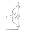
- valve lift law in a given cylinder can be that in Figure 2: the exhaust valve 3 follows the curve E; the valve intake 2 follows curve A while the specific valve follows curve E ', i.e. it opens at the same time as the valve exhaust but only closes when the intake valve closes closed. This makes it possible to obtain the cylinder to cylinder transfer according to the invention.
- the transfer means comprises a common conduit 5 which opens out in each of the specific holes 4.
- the transfer tube (s) 5 can be thermally insulated, using a ceramic 8 for example. She can also be heated by specific means 8 '. So the gases that pass through transfer tubing 5 do not lose or even gain calories when they arrive in the cylinder. Self-ignition is like this improved since we know that the temperature of the recycled gases is a important parameter, which promotes self-ignition.
- FIG. 3 shows schematically another embodiment of the invention which differs from that of FIG. 1 by the addition of a tube 9 which opens into the common tubing 5.
- a valve 10 is preferably disposed in the tubing 9, near its outlet in the tubing common 5.
- valve 4 At partial load, the operation is that explained above.
- the lift profile of valve 4 can be that of valve intake (curve A in Figure 2) with the means 10 in position opening: this ensures optimum filling of the cylinders.
- valve 4 can also, at full load, be similar to that of the exhaust valve (curve E in Figure 2), with the means 10 open in order to ensure optimum emptying of the engine.
- each valve 4 is used at full load either as intake or as exhaust. This characteristic therefore improves combustion during this operating phase.
- the means 10 is closed so that we end up with an operation such as described in relation to Figure 1.
- medium 10 is a completely optional addition to the embodiment of Figure 1 because it essentially allows improve operation at full load.
Landscapes
- Engineering & Computer Science (AREA)
- Chemical & Material Sciences (AREA)
- Combustion & Propulsion (AREA)
- Mechanical Engineering (AREA)
- General Engineering & Computer Science (AREA)
- Output Control And Ontrol Of Special Type Engine (AREA)
- Exhaust-Gas Circulating Devices (AREA)
- Combustion Methods Of Internal-Combustion Engines (AREA)
- Valve Device For Special Equipments (AREA)
- Control Of Throttle Valves Provided In The Intake System Or In The Exhaust System (AREA)
Description
La présente invention concerne les moteurs à combustion interne 4 temps à auto-allumage contrôlé.The present invention relates to internal combustion engines 4 controlled self-ignition time.
L'auto-allumage contrôlé est un phénomène connu dans les moteurs 2 temps. Ce type de combustion présente des avantages au niveau des émissions de polluants : on obtient notamment de faibles émissions d'hydrocarbures et d'oxydes d'azote. En outre, une remarquable régularité cyclique est réalisée lors de la combustion en auto-allumage.Controlled self-ignition is a known phenomenon in engines 2 stroke. This type of combustion has advantages in terms of pollutant emissions: in particular, low emissions are obtained of hydrocarbons and nitrogen oxides. In addition, remarkable regularity cyclic is performed during self-ignition combustion.
L'auto-allumage est un phénomène qui permet d'initier la combustion grâce à des gaz brûlés résiduels, qui restent dans la chambre de combustion après la combustion.Self-ignition is a phenomenon that initiates combustion thanks to residual burnt gases, which remain in the combustion chamber after combustion.
L'auto-allumage est réalisé en contrôlant la quantité de gaz résiduels et son mélange avec les gaz frais (non encore brûlés). Les gaz résiduels (gaz brûlés chauds) initient la combustion des gaz frais grâce à une combinaison de température et de présence d'espèces actives (radicaux).Self-ignition is achieved by controlling the amount of residual gas and its mixture with the fresh gases (not yet burnt). Residual gases (hot burnt gases) initiate the combustion of fresh gases through a combination of temperature and presence of active species (radicals).
Dans les moteurs 2 temps, la présence de gaz résiduels est "inhérente" à la combustion. En effet, lorsque la charge du moteur diminue, la quantité de gaz frais diminue ce qui entraíne une augmentation de la quantité de gaz résiduels (gaz brûlés du ou des cycles précédents qui ne sont pas sortis du cylindre). Le moteur 2 temps fonctionne donc avec une recirculation interne (ou EGR interne) des gaz brûlés à charge partielle. Toutefois, la présence de cet EGR interne n'est pas suffisante pour obtenir le fonctionnement souhaité en auto-allumage. Les travaux des chercheurs montrent aussi qu'il faut contrôler et limiter le mélange entre cet EGR interne et les gaz frais.In 2-stroke engines, the presence of residual gases is "inherent" to combustion. Indeed, when the engine load decreases, the amount of fresh gas decreases which leads to an increase in amount of residual gas (gas burned from the previous cycle (s) which does not have not left the cylinder). The 2-stroke engine therefore works with a internal recirculation (or internal EGR) of burnt gases at partial load. However, the presence of this internal EGR is not sufficient to obtain the desired operation in auto-ignition. Researchers' work also show that it is necessary to control and limit the mixing between this internal EGR and fresh gases.
La technologie d'auto-allumage contrôlé appliquée au moteur quatre temps, est particulièrement intéressante car elle permet de faire fonctionner le moteur avec un mélange extrêmement dilué, avec des richesses très faibles et des émissions d'oxydes d'azote ultra faibles.Controlled self-ignition technology applied to the four engine time, is particularly interesting because it allows to operate the engine with an extremely diluted mixture, with very rich low and ultra low nitrogen oxide emissions.
Cependant cette technologie se heurte à une difficulté technologique importante qui est le fait que pour l'obtenir sans bénéficier de l'effet EGR interne du moteur 2 temps, il est nécessaire soit d'augmenter très fortement le taux de compression du moteur (avec des problèmes de cliquetis à charge élevée), soit de réchauffer très fortement (plusieurs centaines de degrés C) les gaz frais admis, soit de combiner les deux phénomènes.However, this technology faces a technological difficulty important which is the fact that to obtain it without benefiting from the EGR effect internal of the 2-stroke engine, it is necessary either to increase very sharply engine compression ratio (with knocking problems under load high), or to heat very strongly (several hundred degrees C) fresh gas admitted, or to combine the two phenomena.
Des solutions pour diminuer les exigences en niveau de pression et de température pour les moteurs 4 temps peuvent partiellement être trouvées par le biais d'additifs appropriés dans le carburant. La demande de brevet française FR 2 738 594 illustre une solution de ce type.Solutions to reduce the pressure level requirements and temperature for 4-stroke engines can be partially found through suitable additives in the fuel. The request of French patent FR 2 738 594 illustrates a solution of this type.
Pour les moteurs 4 temps il est connu, par exemple par la demande internationale PCT, WO 93/16276 de combiner un calage variable de la distribution avec un système anti-retour à l'admission dans le but de diminuer les pertes par pompage à charge partielle. Cette solution permet alors de fonctionner avec le papillon d'admission le plus ouvert possible.For 4-stroke engines it is known, for example by demand PCT, WO 93/16276 to combine a variable calibration of the distribution with a non-return system on admission for the purpose of reduce pumping losses at partial load. This solution allows then operate with the intake valve as open as possible.
La demande de brevet français EN. 97/02.822 déposée au nom de la demanderesse décrit un contrôle de l'auto-allumage dans un moteur quatre temps. Plus précisément, ce document préconise, à charge partielle, de minimiser le mélange des gaz frais avec les gaz brûlés enfermés dans la chambre de combustion, en retardant le plus possible la fermeture de l'échappement. Il s'agit donc d'un recyclage "interne" qui permet de stratifier les gaz dans la chambre de combustion.The French patent application EN. 97 / 02.822 filed on behalf of the Applicant describes a self-ignition control in a four engine time. More specifically, this document recommends, at partial charge, minimize mixing of the fresh gases with the burnt gases trapped in the combustion chamber, delaying the closing of the the exhaust. It is therefore an "internal" recycling which allows stratification the gases in the combustion chamber.
La demande de brevet EN. 97/11.279 déposée au nom du demandeur vise aussi à minimiser à charge partielle le mélange des gaz frais avec les gaz brûlés contenus dans la chambre de combustion, dans le but de contrôler et de favoriser la combustion en auto-allumage. Cependant cet art antérieur propose de transférer les gaz brûlés depuis l'échappement jusque dans l'admission via un conduit spécifique qui débouche juste en amont de la chambre de combustion, dans un conduit d'alimentation en air. La charge air frais-carburant est admise séparément et tardivement, via un deuxième conduit. Une introduction successive des charges est donc prévue.The EN patent application. 97 / 11.279 filed in the name of the applicant also aims to minimize at partial load the mixing of fresh gases with burnt gases contained in the combustion chamber, for the purpose of control and promote self-ignition combustion. However this art previous proposes to transfer the burnt gases from the exhaust to in the admission via a specific conduit which leads just upstream of the combustion chamber, in an air supply duct. Load fresh air-fuel is admitted separately and late, via a second leads. A successive introduction of the charges is therefore planned.
Cependant cette solution crée une dilution très importante des gaz brûlés recyclés, par l'air, avant l'entrée dans la chambre de combustion, ce qui peut poser problème.However, this solution creates a very significant dilution of the gases. burned recycled by air before entering the combustion chamber, this which can be problematic.
Il est également connu par le document DE-A- 4 036 537 de stocker sous pression les gaz d'échappement dans un accumulateur par un orifice spécifique prévu dans le moteur et de les introduire par ce même orifice dans la chambre de combustion pour comprimer l'air frais qui s'y trouve.It is also known from document DE-A- 4,036,537 to store pressurized exhaust gases in an accumulator through an orifice specific provided in the engine and introduce them through this same orifice in the combustion chamber to compress the fresh air there.
Cette disposition entraíne un refroidissement des gaz d'échappement et ne permet pas d'utiliser ces gaz pour favoriser l'autoallumage de l'air frais.This arrangement causes cooling of the exhaust gases. and does not allow these gases to be used to promote the self-ignition of fresh air.
La présente invention vise à réaliser un auto-allumage contrôlé dans des moteurs 4 temps multi-cylindre qui soit très simple, donc fiable, de mise en oeuvre aisée et qui favorise au maximum la stratification des gaz brûlés dans la chambre de combustion. De plus les gaz brûlés conservent, selon l'invention, leur température ce qui est favorable à l'auto-combustion.The present invention aims to achieve controlled self-ignition in very simple, therefore reliable, 4-stroke multi-cylinder engines easy to use and which maximizes the stratification of the burnt gases in the combustion chamber. In addition, the burnt gases retain, depending on the invention, their temperature which is favorable to self-combustion.
Ainsi la présente invention a pour objet un procédé de combustion par auto-allumage contrôlé d'un moteur 4 temps comprenant plusieurs cylindres ayant chacun au moins un premier moyen d'admission et au moins un premier moyen d'échappement.Thus the subject of the present invention is a method of combustion by controlled self-ignition of a 4-stroke engine comprising several cylinders each having at least a first means of admission and at least one first means of exhaust.
Selon l'invention, le procédé consiste pendant le fonctionnement à charge partielle,
- à transférer, via au moins un orifice spécifique de chaque cylindre et un moyen de transfert approprié, des gaz d'échappement depuis un cylindre en phase d'échappement vers un autre cylindre en phase d'admission,
- à ouvrir l'orifice spécifique en même temps que l'ouverture du premier moyen d'échappement et à fermer ledit orifice en même temps que la fermeture du premier moyen d'admission.
- to transfer, via at least one specific orifice of each cylinder and an appropriate transfer means, exhaust gases from a cylinder in the exhaust phase to another cylinder in the intake phase,
- opening the specific orifice at the same time as the opening of the first exhaust means and closing said orifice at the same time as the closing of the first intake means.
Le procédé selon l'invention, consiste en outre à contrôler la répartition du débit des gaz d'échappement entre le premier moyen d'échappement et le moyen spécifique.The method according to the invention also consists in controlling the distribution of the exhaust gas flow between the first means exhaust and the specific means.
En outre, le procédé peut consister à isoler thermiquement et/ou à réchauffer les gaz d'échappement transférés dans ledit moyen de transfert approprié, afin d'améliorer encore l'auto-combustion. In addition, the process can consist of thermally insulating and / or reheating the exhaust gases transferred into said transfer means suitable, in order to further improve self-combustion.
Selon un mode de réalisation de l'invention, on utilise un conduit commun pour le transfert des gaz d'échappementAccording to one embodiment of the invention, a conduit is used common for exhaust gas transfer
De façon particulière, à pleine et forte charges, on utilise le conduit commun et certains au moins des orifices spécifiques pour admettre une charge ou bien pour faire évacuer des gaz d'échappement.In particular, at full and heavy loads, the conduit is used common and at least some specific orifices to admit a charge or to evacuate exhaust gases.
Selon un autre mode de réalisation de l'invention, on utilise pour le transfert des gaz d'échappement cylindre à cylindre, un ensemble de conduits reliant les cylindres deux à deux.According to another embodiment of the invention, one uses for the transfer of exhaust gases cylinder to cylinder, a set of conduits connecting the cylinders two by two.
La présente invention concerne en outre un moteur à combustion interne à 4 temps fonctionnant en auto-allumage contrôlé et comprenant plusieurs cylindres ayant chacun au moins un premier moyen d'admission et au moins un premier moyen d'échappement.The present invention further relates to a combustion engine internal 4-stroke operating in controlled self-ignition and comprising several cylinders each having at least a first intake means and at least a first exhaust means.
Conformément à l'invention, chaque cylindre comprend en outre au moins un moyen spécifique destiné au passage des gaz d'échappement depuis un cylindre en phase d'échappement vers un autre cylindre en phase d'admission ainsi qu'un moyen de transfert associé, pendant le fonctionnement à charge partielle, et le moyen spécifique est ouvert en même temps que l'ouverture du premier moyen d'échappement et est fermé en même temps que la fermeture du premier moyen d'admission.According to the invention, each cylinder further comprises at less specific means for the passage of exhaust gases from a cylinder in exhaust phase to another cylinder in phase of admission as well as an associated means of transfer, during the partial load operation, and the specific means is open at the same time as the opening of the first exhaust means and is closed at the same time as the closure of the first means of admission.
Un moyen d'isolation thermique et/ou de chauffage du moyen de transfert peut par ailleurs être prévu sans sortir du cadre de l'invention.A means of thermal insulation and / or heating of the means of transfer can also be provided without departing from the scope of the invention.
De façon avantageuse, le moteur comprend en outre un moyen de répartition des gaz d'échappement entre le premier moyen d'échappement et le moyen spécifique, à charge partielle. Advantageously, the engine further comprises a means of distribution of the exhaust gases between the first exhaust means and the specific means, at partial charge.
Le moyen de répartition des gaz d'échappement peut comprendre soit un premier moyen de vannage disposé à proximité du premier moyen d'échappement, soit un deuxième moyen de vannage placé près du moyen spécifique de passage des gaz, soit les deux vannages.The means for distributing the exhaust gases may comprise either a first winnowing means arranged near the first means exhaust, or a second means of winnowing placed near the means specific gas passage, ie the two winnowing.
Selon un mode de réalisation, ledit moyen de transfert comprend un conduit commun qui débouche dans chacun des orifices spécifiques.According to one embodiment, said transfer means comprises a common conduit which opens into each of the specific orifices.
Avantageusement, ledit conduit commun présente en outre un orifice dans lequel débouche un conduit équipé d'un moyen de régulation du débit des gaz.Advantageously, said common conduit also has an orifice into which opens a conduit equipped with a flow regulation means gases.
Conformément à un autre mode de réalisation de l'invention, le moyen de transfert comprend un ensemble de conduites reliant les cylindres deux à deux.In accordance with another embodiment of the invention, the means transfer includes a set of lines connecting the two cylinders to of them.
D'autres caractéristiques, détails, avantages de la présente invention apparaítront mieux à la lecture de la description qui va suivre, faite à titre illustratif et nullement limitatif en référence aux dessins annexés sur lesquels :
- La figure 1 est une coupe schématique d'un mode de réalisation de l'invention;
- La figure 2 est un graphe donnant la loi de levée des soupapes sur un cycle;
- La figure 3 est une coupe schématique d'un autre mode de réalisation de l'invention.
- Figure 1 is a schematic section of an embodiment of the invention;
- Figure 2 is a graph giving the valve lift law on a cycle;
- Figure 3 is a schematic section of another embodiment of the invention.
La figure 1 illustre le cas d'un moteur ayant quatre cylindres 1.
L'invention s'applique en fait à tous les moteurs comportant au moins deux
cylindres.FIG. 1 illustrates the case of an engine having four
Chaque - cylindre 1 comprend au moins un premier moyen 2
d'admission d'une charge. Par un premier moyen 2 d'admission d'une
charge, il faut ici comprendre un orifice d'admission auquel est associé une
soupape.Each -
Chaque cylindre comprend en outre un premier moyen d'échappement 3 constitué classiquement d'un orifice d'échappement et d'une soupape associée.Each cylinder further comprises a first means exhaust 3 conventionally consisting of an exhaust orifice and an associated valve.
Par ailleurs, chaque cylindre 1 comprend un orifice spécifique 4 dans
lequel débouche un conduit de transfert des gaz d'échappement. Une
soupape coopère avec l'orifice spécifique 4.Furthermore, each
Dans chaque cylindre, un premier moyen de vannage 6 est disposé à proximité du premier moyen d'échappement 3 ; tandis qu'un deuxième moyen de vannage 7 est placé près de l'orifice spécifique 4. Une commande appropriée et coordonnée de l'ouverture de chaque moyen de vannage 6, 7 permet de réguler et de répartir le débit des gaz entre l'échappement classique 3 et l'orifice spécifique 4.In each cylinder, a first valve means 6 is arranged at proximity of the first exhaust means 3; while a second valve 7 is placed near the specific opening 4. A control appropriate and coordinated opening of each winnowing means 6, 7 allows to regulate and distribute the gas flow between the exhaust classic 3 and the specific orifice 4.
Il est possible, sans sortir du cadre de l'invention, de n'envisager qu'un seul des deux vannages.It is possible, without departing from the scope of the invention, to envisage only one of the two winnowing.
Chaque cylindre comprend donc au moins un orifice spécifique 4 qui coopère avec une soupape. Il peut en comprendre plusieurs. De même pour les moyens d'admission et d'échappement.Each cylinder therefore comprises at least one specific orifice 4 which cooperates with a valve. He can understand several. The same applies to the intake and exhaust means.
Les orifices 4 étant reliés au moyen de transfert, les gaz d'échappement ou un autre fluide peuvent y transitent lors d'un transfert d'un cylindre vers un autre cylindre.The orifices 4 being connected to the transfer means, the gases exhaust or other fluid can pass through during a transfer from a cylinder to another cylinder.
Plus précisément, à charge partielle, des gaz d'échappement sont transférés depuis un cylindre en phase d'échappement vers un autre cylindre en phase d'admission.More specifically, at partial load, exhaust gases are transferred from one cylinder in exhaust phase to another cylinder in the admission phase.
Le tableau ci-dessous illustre les transferts ainsi réalisés sur un cycle,
pour un moteur 4 cylindres.

Autrement dit, à partir d'un orifice spécifique 4 d'un cylindre donné, une tubulure de transfert qui se dédouble est mise en place : l'une est dirigée vers l'orifice 4 d'un cylindre en retard de phase et elle permet le transfert du cylindre donné vers le cylindre en retard de phase ; la seconde tubulure aboutit sur le cylindre en avance de phase et elle permet le transfert des gaz d'échappement depuis le cylindre en avance vers le cylindre donné.In other words, from a specific orifice 4 of a given cylinder, a transfer tubing which splits is put in place: one is directed towards the orifice 4 of a cylinder with phase delay and it allows the transfer from the given cylinder to the phase lagged cylinder; the second tubing ends on the cylinder in advance of phase and it allows the transfer exhaust gases from the cylinder in advance to the given cylinder.
Si l'on considère des cylindres ayant chacun plusieurs orifices spécifiques 4, dans l'un au moins des orifices spécifiques aboutira une tubulure liée à un cylindre en retard de phase, et dans l'un au moins de l'autre ou des autres orifices spécifiques aboutira une tubulure liée à un cylindre en avance de phase. If we consider cylinders each having several orifices specific 4, in at least one of the specific orifices will lead to a tubing linked to a cylinder lagging in phase, and in at least one of the other or other specific orifices will lead to a tubing linked to a cylinder in phase advance.
La loi de levée des soupapes dans un cylindre donné peut être celle de la figure 2 : la soupape d'échappement 3 suit la courbe E ; la soupape d'admission 2 suit la courbe A tandis que la soupape spécifique suit la courbe E' c'est-à-dire qu'elle s'ouvre en même temps que la soupape d'échappement mais ne se referme que lorsque la soupape d'admission se ferme. Ceci permet d'obtenir le transfert cylindre à cylindre selon l'invention.The valve lift law in a given cylinder can be that in Figure 2: the exhaust valve 3 follows the curve E; the valve intake 2 follows curve A while the specific valve follows curve E ', i.e. it opens at the same time as the valve exhaust but only closes when the intake valve closes closed. This makes it possible to obtain the cylinder to cylinder transfer according to the invention.
Selon un mode de réalisation de l'invention, illustré par les figures 1
ou 3, le moyen de transfert comprend un conduit commun 5 qui débouche
dans chacun des orifices spécifiques 4.According to one embodiment of the invention, illustrated by Figures 1
or 3, the transfer means comprises a
Il est encore envisageable, sans sortir du cadre de l'invention, de prévoir comme moyen de transfert un ensemble de conduites reliant les cylindres deux à deux, et qui permettent par exemple pour un moteur quatre cylindres, d'avoir les transferts selon le tableau ci-dessus.It is still possible, without departing from the scope of the invention, to provide as a means of transfer a set of pipes connecting the cylinders two by two, and which allow for example for a four engine cylinders, to have the transfers according to the table above.
De façon avantageuse, la ou les tubulures de transfert 5 peut être
isolée thermiquement, à l'aide d'une céramique 8 par exemple. Elle peut
aussi être chauffée par des moyens spécifiques 8'. Ainsi les gaz qui
transitent dans une tubulure de transfert 5 ne perdent pas, voire gagnent des
calories lorsqu'ils arrivent dans le cylindre. L'auto-inflammation est ainsi
améliorée puisque l'on sait que la température des gaz recyclés est un
paramètre important, qui favorise l'auto-allumage.Advantageously, the transfer tube (s) 5 can be
thermally insulated, using a ceramic 8 for example. She can
also be heated by specific means 8 '. So the gases that
pass through
La figure 3 schématise un autre mode de réalisation de l'invention qui
diffère de celui de la figure 1 par l'ajout d'une tubulure 9 qui débouche dans
la tubulure commune 5. Un moyen de vannage 10 est préférentiellement
disposé dans la tubulure 9, près de son débouché dans la tubulure
commune 5.Figure 3 shows schematically another embodiment of the invention which
differs from that of FIG. 1 by the addition of a
A charge partielle, le fonctionnement est celui expliqué ci-avant. A
pleine charge, le profil de levé de la soupape 4 peut être celui de la soupape
d'admission (courbe A de la figure 2) avec le moyen 10 en position
d'ouverture : ceci assure un remplissage optimum des cylindres.At partial load, the operation is that explained above. AT
full load, the lift profile of valve 4 can be that of valve
intake (curve A in Figure 2) with the
Le profil de levée de la soupape 4 peut aussi, à pleine charge, être
semblable à celui de la soupape d'échappement (courbe E de la figure 2),
avec le moyen 10 ouvert afin d'assurer une vidange optimale du moteur.
Autrement dit, selon ce mode de réalisation de l'invention, chaque soupape
4 est utilisée à pleine charge soit comme admission soit comme
échappement. Cette caractéristique améliore donc la combustion pendant
cette phase de fonctionnement. Bien entendu, à charge partielle, le moyen
10 est fermé de sorte que l'on se retrouve avec un fonctionnement tel que
décrit en relation avec la figure 1.The lift profile of valve 4 can also, at full load, be
similar to that of the exhaust valve (curve E in Figure 2),
with the
Il convient de noter que le moyen 10 est un ajout totalement facultatif au mode de réalisation de la figure 1 car il permet essentiellement d'améliorer le fonctionnement à pleine charge.It should be noted that the medium 10 is a completely optional addition to the embodiment of Figure 1 because it essentially allows improve operation at full load.
Claims (14)
- Controlled self-ignition combustion process for a 4-stroke engine including a plurality of cylinders (1) each having at least a first induction means (2) and at least a first exhaust means (3), characterised by the fact that it consists, during operation at partial load,of transferring exhaust gases, via at least one specific orifice (4) of each cylinder (1) and a suitable transfer means (5), from a cylinder in the exhaust phase to another cylinder in the induction phase,of opening the specific orifice (4) simultaneously with opening of the first exhaust means (3) and of closing the said orifice simultaneously with closure of the first induction means (2).
- Process as described in claim 1, characterised by the fact that it also consists of controlling the distribution of the flow of exhaust gases between the first exhaust means (3) and the specific means (4).
- Process as described in any one of the preceding claims, characterised by the fact that it consists of thermally insulating and/or heating the exhaust gases transferred in the said suitable transfer means.
- Process as described in any one of the preceding claims, characterised by the fact that a common pipe (5) is used for transfer of the exhaust gases.
- Process as described in claim 4, characterised by the fact that, at full and heavy loads, the common pipe (5) and at least certain of the specific orifices (4) are used for induction of a charge or for evacuation of the exhaust gases.
- Process as described in any one of claims 1 to 3, characterised by the fact that a set of pipes linking the cylinders in pairs is used for the transfer of the exhaust gases from cylinder to cylinder.
- 4-stroke internal combustion engine operating with controlled self-ignition and including a plurality of cylinders (1) each having at least a first induction means (2) and at least a first exhaust means (3), characterised by the fact that each cylinder (1) also includes at least one specific means (4) intended for passage of the exhaust gases from a cylinder in the exhaust phase to another cylinder in the induction phase and an associated transfer means (5), during operation at partial load, and by the fact that the specific means (4) is opened simultaneously with the opening of the first exhaust means (3) and is closed simultaneously with closure of the first induction means (2).
- Internal combustion engine as described in claim 7, characterised by the fact that it also includes a means for thermal insulation (8) and/or heating (8') of the said transfer means.
- Internal combustion engine as described in either one of claims 7 or 8, characterised by the fact that it also includes a means (6, 7) for distribution of the exhaust gases between the first exhaust means (3) and the specific means (4), at partial load.
- Internal combustion engine as described in claim 9, characterised by the fact that the means for distribution of the gases comprises a first valving means (6) arranged in the proximity of the first exhaust means (3).
- Internal combustion engine as described in either one of claims 9 or 10, characterised by the fact that the said means for distribution of the gases comprises a second valving means (7) positioned close to the specific means for passage of the gases (4).
- Internal combustion engine as described in any one of claims 7 to 11, characterised by the fact that the said transfer means comprises a common pipe (5) which opens into each of the specific orifices (4).
- Internal combustion engine as described in claim 12, characterised by the fact that the said common pipe (5) also has an orifice into which opens a pipe (9) provided with a means (10) for adjusting the flow-rate of the gases.
- Internal combustion engine as described in any one of claims 7 to 11, characterised by the fact that the said transfer means comprises a set of pipes linking the cylinders in pairs.
Applications Claiming Priority (2)
| Application Number | Priority Date | Filing Date | Title |
|---|---|---|---|
| FR9805925A FR2777947B1 (en) | 1998-04-27 | 1998-04-27 | CONTROLLED SELF-IGNITION COMBUSTION PROCESS AND 4-STROKE ENGINE ASSOCIATED WITH TRANSFER DUCT BETWEEN CYLINDERS AND DEDICATED VALVE |
| FR9805925 | 1998-04-27 |
Publications (2)
| Publication Number | Publication Date |
|---|---|
| EP0953745A1 EP0953745A1 (en) | 1999-11-03 |
| EP0953745B1 true EP0953745B1 (en) | 2003-10-15 |
Family
ID=9526229
Family Applications (1)
| Application Number | Title | Priority Date | Filing Date |
|---|---|---|---|
| EP99400895A Expired - Lifetime EP0953745B1 (en) | 1998-04-27 | 1999-04-13 | Controlled self-ignition combustion process and associated 4 stroke combustion engine with transfer conduit between cylinders and valve for it |
Country Status (5)
| Country | Link |
|---|---|
| US (2) | US6178933B1 (en) |
| EP (1) | EP0953745B1 (en) |
| JP (1) | JPH11343887A (en) |
| DE (1) | DE69912019T2 (en) |
| FR (1) | FR2777947B1 (en) |
Families Citing this family (28)
| Publication number | Priority date | Publication date | Assignee | Title |
|---|---|---|---|---|
| DE19854461C1 (en) * | 1998-11-25 | 2000-03-09 | Daimler Chrysler Ag | Automobile internal combustion engine has pivoted valve plate for adjusting exhaust gas feedback between exhaust gas line and air intake line |
| DE10009180C2 (en) * | 2000-02-26 | 2002-04-25 | Daimler Chrysler Ag | Process for producing a homogeneous mixture for self-igniting internal combustion engines and for controlling the combustion process |
| DE10197229T5 (en) | 2001-04-09 | 2004-04-22 | Daihatsu Motor Co., Ltd., Ikeda | Multi-cylinder internal combustion engine |
| GB0115812D0 (en) * | 2001-06-28 | 2001-08-22 | Ford Global Tech Inc | Engine with controlled auto-ignition |
| US7182050B2 (en) * | 2002-01-31 | 2007-02-27 | Mazda Motor Corporation | Control device for spark-ignition engine |
| JP3956783B2 (en) * | 2002-07-02 | 2007-08-08 | マツダ株式会社 | Control device for spark ignition engine |
| JP3846393B2 (en) * | 2002-09-30 | 2006-11-15 | マツダ株式会社 | Control device for spark ignition engine |
| WO2004033888A2 (en) * | 2002-10-04 | 2004-04-22 | Honeywell International Inc. | Internal combustion engine system |
| US6758195B1 (en) * | 2002-11-26 | 2004-07-06 | Daimlerchrysler Corporation | System and method for fast exhaust gas recirculation in a combustion chamber |
| US6968825B2 (en) * | 2003-06-06 | 2005-11-29 | Mazda Motor Corporation | Control device for spark-ignition engine |
| US20040261774A1 (en) * | 2003-06-25 | 2004-12-30 | Eft Neil Wallace | Gas-assisted internal combustion engine |
| FR2866388B1 (en) * | 2004-02-18 | 2009-05-29 | Renault Sas | EXHAUST GAS RECIRCULATION SYSTEM OF AN INTERNAL COMBUSTION ENGINE |
| NZ531314A (en) * | 2004-02-23 | 2006-10-27 | Shuttleworth Axial Motor Compa | Recirculation system for motor |
| SE531208C8 (en) * | 2004-03-31 | 2009-02-17 | ||
| JP3994990B2 (en) * | 2004-07-21 | 2007-10-24 | 株式会社豊田中央研究所 | Fuel injection device |
| EP1811154B1 (en) * | 2004-10-20 | 2013-12-11 | Koichi Hatamura | Engine control method |
| JP4434056B2 (en) * | 2005-03-25 | 2010-03-17 | 株式会社豊田自動織機 | Premixed compression ignition engine |
| DE102006014996A1 (en) * | 2006-03-31 | 2007-10-04 | Robert Bosch Gmbh | Method for operating an Otto engine with direct fuel injection comprises passing and leaving residual gas in the combustion chamber using an internal and external exhaust gas re-circulating unit |
| US7559317B2 (en) * | 2006-04-24 | 2009-07-14 | Barnett Joel Robinson | Internal combustion engine with single-port holding tank for elevated expansion ratio |
| JP2008169818A (en) * | 2007-01-15 | 2008-07-24 | Yamaha Motor Co Ltd | 4-cycle internal combustion engine and vehicle |
| US7765994B2 (en) * | 2007-07-12 | 2010-08-03 | Ford Global Technologies, Llc | Cylinder charge temperature control for an internal combustion engine |
| EP2065586A1 (en) * | 2007-11-29 | 2009-06-03 | Perkins Engines Company Limited | Improved breathing for an internal combustion engine |
| GB0806110D0 (en) * | 2008-04-04 | 2008-05-14 | Ma Thomas T H | Method for supplying boosted EGR in IC engine |
| FR2938880A1 (en) * | 2008-11-21 | 2010-05-28 | Peugeot Citroen Automobiles Sa | Engine i.e. internal combustion engine, for vehicle, has positioning unit utilized such that transferring valve discharges exhaust gas during exhaust phase and allows exhaust gas to cylinders during compression phase |
| GB2473481B (en) * | 2009-09-14 | 2015-06-17 | Univ Brunel | Method for supplying EGR in an IC engine |
| US20110061633A1 (en) * | 2009-09-16 | 2011-03-17 | Barnett Joel Robinson | Internal combustion engine having intake manifold combined with holding tank |
| US8146572B2 (en) * | 2009-12-21 | 2012-04-03 | Chrysler Group Llc | Cooled exhaust gas recirculation system with cylinder-level control |
| US10760504B2 (en) * | 2016-12-20 | 2020-09-01 | Volvo Truck Corporation | Method for controlling an internal combustion engine |
Citations (1)
| Publication number | Priority date | Publication date | Assignee | Title |
|---|---|---|---|---|
| DE3903474A1 (en) * | 1988-02-25 | 1989-09-07 | Avl Verbrennungskraft Messtech | Method for operating an internal combustion engine |
Family Cites Families (17)
| Publication number | Priority date | Publication date | Assignee | Title |
|---|---|---|---|---|
| CA938517A (en) * | 1970-02-19 | 1973-12-18 | H. Weaving John | Atmospheric pollution control arrangement for internal combustion engine |
| US3789807A (en) | 1972-06-19 | 1974-02-05 | J Pinkerton | Dual combustion process for an internal combustion engine |
| US3785355A (en) * | 1973-03-02 | 1974-01-15 | Gen Motors Corp | Engine with internal charge dilution and method |
| US4041910A (en) * | 1975-04-02 | 1977-08-16 | The United States Of America As Represented By The Administrator Of The National Aeronautics And Space Administration | Combustion engine |
| JPS5552049Y2 (en) * | 1976-01-31 | 1980-12-03 | ||
| US4159700A (en) * | 1976-10-18 | 1979-07-03 | Mccrum William H | Internal combustion compound engines |
| JPS5390505A (en) * | 1977-01-20 | 1978-08-09 | Isuzu Motors Ltd | Exhaust gas purifier for internal combustion engine having chamber |
| JPS5392017A (en) * | 1977-01-24 | 1978-08-12 | Isuzu Motors Ltd | Exhaust circulation device for internal combustion engine with by-chamber |
| DE2740045A1 (en) * | 1977-09-06 | 1979-03-15 | Bayerische Motoren Werke Ag | METHOD FOR PARTIAL LOAD CONTROL OF COMBUSTION MACHINERY |
| JPS5846667B2 (en) * | 1977-12-02 | 1983-10-18 | トヨタ自動車株式会社 | Exhaust gas recirculation device for multi-cylinder internal combustion engines |
| JPS54116512A (en) * | 1978-03-02 | 1979-09-10 | Toyota Motor Corp | Internal combustion engine with reservoirs |
| US4282845A (en) | 1979-03-21 | 1981-08-11 | Toyota Jidosha Kogyo Kabushiki Kaisha | Internal combustion engine with exhaust gas accumulation chamber |
| DE3125647A1 (en) * | 1981-06-30 | 1983-01-13 | Robert Bosch Gmbh, 7000 Stuttgart | "INTERNAL COMBUSTION ENGINE WITH SEVERAL CYLINDERS" |
| BE1000774A5 (en) * | 1987-07-30 | 1989-04-04 | Schmitz Gerhard | SIX - TIME INTERNAL COMBUSTION ENGINE. |
| JPH0658094B2 (en) * | 1989-10-31 | 1994-08-03 | いすゞ自動車株式会社 | Reburning control device for alcohol engine |
| DE4036537C1 (en) * | 1990-11-16 | 1991-11-07 | Artur 7437 Westerheim De Krause | IC engine toxics reduction system - involves mixing off-gas from previous cycle to fresh air content |
| US5970944A (en) * | 1997-01-21 | 1999-10-26 | Isuzu Ceramics Research Institute Co., Ltd. | Combustion chamber structure in engines |
-
1998
- 1998-04-27 FR FR9805925A patent/FR2777947B1/en not_active Expired - Fee Related
-
1999
- 1999-04-13 EP EP99400895A patent/EP0953745B1/en not_active Expired - Lifetime
- 1999-04-13 DE DE69912019T patent/DE69912019T2/en not_active Expired - Fee Related
- 1999-04-26 US US09/299,083 patent/US6178933B1/en not_active Expired - Fee Related
- 1999-04-26 US US09/299,085 patent/US6427644B1/en not_active Expired - Fee Related
- 1999-04-27 JP JP11120181A patent/JPH11343887A/en active Pending
Patent Citations (1)
| Publication number | Priority date | Publication date | Assignee | Title |
|---|---|---|---|---|
| DE3903474A1 (en) * | 1988-02-25 | 1989-09-07 | Avl Verbrennungskraft Messtech | Method for operating an internal combustion engine |
Also Published As
| Publication number | Publication date |
|---|---|
| FR2777947A1 (en) | 1999-10-29 |
| US6427644B1 (en) | 2002-08-06 |
| FR2777947B1 (en) | 2000-11-17 |
| EP0953745A1 (en) | 1999-11-03 |
| US6178933B1 (en) | 2001-01-30 |
| DE69912019D1 (en) | 2003-11-20 |
| DE69912019T2 (en) | 2004-04-29 |
| JPH11343887A (en) | 1999-12-14 |
Similar Documents
| Publication | Publication Date | Title |
|---|---|---|
| EP0953745B1 (en) | Controlled self-ignition combustion process and associated 4 stroke combustion engine with transfer conduit between cylinders and valve for it | |
| EP0863301B1 (en) | Process for controlling auto ignition in a four stroke engine | |
| EP1096118B1 (en) | Controlled self-ignition combustion process and four cycle engine with transfer conduits between exhaust and intake conduit | |
| EP2083155B1 (en) | Method for scanning residual combustion gas with double intake valve lift of a supercharged direct-injection internal combustion engine, in particular a diesel engine | |
| FR2768180A1 (en) | OPERATING PROCESS OF A 4-STROKE ENGINE, IN CONTROLLED SELF-IGNITION | |
| EP1914409B1 (en) | Internal combustion engine control method and engine using the method | |
| EP0953744B1 (en) | Controlled self-ignition combustion process and associated 4 stroke combustion engine with residual gas storage volume and valve there for | |
| EP1195505B1 (en) | Method to control auto-ignition in a four-stroke engine | |
| EP2354499B1 (en) | Method for scavenging residual burnt gas in a supercharged direct-injection internal combustion engine operating at partial loads. | |
| EP1726805B1 (en) | Method to control the exhaust gas scavenging of an engine with indirect injection, in particular supercharged engine, and engine using such a method | |
| FR2744170A1 (en) | Four stroke Diesel engine operating with turbo-charger | |
| EP1790841A1 (en) | Method of controlling the intake and/or exhaust of at least one deactivated cylinder of an internal combustion engine | |
| WO2013190198A1 (en) | Engine unit with a recirculation line | |
| FR2835882A1 (en) | INTERNAL COMBUSTION ENGINE, ESPECIALLY GASOLINE, EQUIPPED WITH A TURBOCHARGER AND A VARIABLE DISTRIBUTION | |
| FR2868481A1 (en) | METHOD FOR CONTROLLING THE RECIRCULATION OF EXHAUST GASES OF AN INTERNAL COMBUSTION-BASED SUPERVISOR ENGINE AND ENGINE USING SUCH A METHOD | |
| WO2014001667A1 (en) | Engine unit with a recirculation line | |
| FR2914366A1 (en) | Internal combustion engine i.e. controlled ignition gasoline internal combustion engine, function controlling method for vehicle, involves varying exhaust back pressure for allowing pressure to oppose to gas pressure to control gas quantity | |
| WO2001051786A1 (en) | Method and device for improving the operation of supercharged internal combustion engines at low engine revs | |
| FR2867517A1 (en) | OPTIMIZED EXHAUST GAS RECIRCULATION METHOD FOR THERMAL MOTOR, AND ENGINE EMPLOYING SAID METHOD | |
| FR2933450A1 (en) | Fuel vaporization facilitating method for diesel engine, involves introducing intake fluid into combustion chamber, closing exhaust valve before end of intake phase, and closing intake valve in vicinity of end of intake phase | |
| FR2883331A1 (en) | METHOD FOR CONTROLLING A COMPRESSION IGNITION ENGINE FOR REALIZING INTERNAL GAS RECIRCULATION | |
| EP2273086A1 (en) | Method of controlling the intake of a supercharged internal combustion engine including a scavenging operation for the burnt gas | |
| FR2904049A1 (en) | THERMAL MOTOR HAVING TWO ADMISSION DUCTS, ONE OF WHICH IS USED FOR SWEEPING THE COMBUSTION CHAMBER, MODULE FOR MANAGING SUCH A THERMAL MOTOR, AND METHOD FOR MANAGING A THERMAL MOTOR |
Legal Events
| Date | Code | Title | Description |
|---|---|---|---|
| PUAI | Public reference made under article 153(3) epc to a published international application that has entered the european phase |
Free format text: ORIGINAL CODE: 0009012 |
|
| AK | Designated contracting states |
Kind code of ref document: A1 Designated state(s): DE GB IT NL SE |
|
| AX | Request for extension of the european patent |
Free format text: AL;LT;LV;MK;RO;SI |
|
| 17P | Request for examination filed |
Effective date: 20000503 |
|
| AKX | Designation fees paid |
Free format text: DE GB IT NL SE |
|
| 17Q | First examination report despatched |
Effective date: 20020226 |
|
| GRAH | Despatch of communication of intention to grant a patent |
Free format text: ORIGINAL CODE: EPIDOS IGRA |
|
| GRAS | Grant fee paid |
Free format text: ORIGINAL CODE: EPIDOSNIGR3 |
|
| GRAA | (expected) grant |
Free format text: ORIGINAL CODE: 0009210 |
|
| AK | Designated contracting states |
Kind code of ref document: B1 Designated state(s): DE GB IT NL SE |
|
| PG25 | Lapsed in a contracting state [announced via postgrant information from national office to epo] |
Ref country code: NL Free format text: LAPSE BECAUSE OF FAILURE TO SUBMIT A TRANSLATION OF THE DESCRIPTION OR TO PAY THE FEE WITHIN THE PRESCRIBED TIME-LIMIT Effective date: 20031015 Ref country code: GB Free format text: LAPSE BECAUSE OF FAILURE TO SUBMIT A TRANSLATION OF THE DESCRIPTION OR TO PAY THE FEE WITHIN THE PRESCRIBED TIME-LIMIT Effective date: 20031015 |
|
| REG | Reference to a national code |
Ref country code: GB Ref legal event code: FG4D Free format text: NOT ENGLISH |
|
| REF | Corresponds to: |
Ref document number: 69912019 Country of ref document: DE Date of ref document: 20031120 Kind code of ref document: P |
|
| PG25 | Lapsed in a contracting state [announced via postgrant information from national office to epo] |
Ref country code: SE Free format text: LAPSE BECAUSE OF FAILURE TO SUBMIT A TRANSLATION OF THE DESCRIPTION OR TO PAY THE FEE WITHIN THE PRESCRIBED TIME-LIMIT Effective date: 20040115 |
|
| NLV1 | Nl: lapsed or annulled due to failure to fulfill the requirements of art. 29p and 29m of the patents act | ||
| GBV | Gb: ep patent (uk) treated as always having been void in accordance with gb section 77(7)/1977 [no translation filed] |
Effective date: 20031015 |
|
| PLBE | No opposition filed within time limit |
Free format text: ORIGINAL CODE: 0009261 |
|
| STAA | Information on the status of an ep patent application or granted ep patent |
Free format text: STATUS: NO OPPOSITION FILED WITHIN TIME LIMIT |
|
| 26N | No opposition filed |
Effective date: 20040716 |
|
| PGFP | Annual fee paid to national office [announced via postgrant information from national office to epo] |
Ref country code: DE Payment date: 20080423 Year of fee payment: 10 |
|
| PGFP | Annual fee paid to national office [announced via postgrant information from national office to epo] |
Ref country code: IT Payment date: 20080421 Year of fee payment: 10 |
|
| PG25 | Lapsed in a contracting state [announced via postgrant information from national office to epo] |
Ref country code: DE Free format text: LAPSE BECAUSE OF NON-PAYMENT OF DUE FEES Effective date: 20091103 |
|
| PG25 | Lapsed in a contracting state [announced via postgrant information from national office to epo] |
Ref country code: IT Free format text: LAPSE BECAUSE OF NON-PAYMENT OF DUE FEES Effective date: 20090413 |